

Post your DIY aero pics


Yes, I've wondered the same thing on the splitter/undertray. For fire hazard reasons I'd rather not have just a plain wood undertray.
I might send a note to the regional tech guy asking for clarification.
I might send a note to the regional tech guy asking for clarification.
Reply
 0
0

0

Just spray the wood with gelocat rather than paint. They will never know the difference if you dont tell anyone.
Reply
0
0

Senior Member
Joined: Dec 2010
Posts: 993
Total Cats: 57
From: Auckland, NZ
3 mm mdf is not a fire hazard, bends very easily and can be epoxied or just painted...
it's not waterproof without a decent paint and is not the lightest but would work fine, I would think.
it's not waterproof without a decent paint and is not the lightest but would work fine, I would think.
Reply
0
0


nice work. Due to the low pressure region behind the car, they will naturally draw air out. That will definitely help smooth the flow of air. Do you have any way of feeding air into it to help speed it up?
Reply
0
0

ʎpunq qoq
Joined: Jan 2014
Posts: 604
Total Cats: 202
From: Western Australia
Heya all, I have been working on a custom 3D printed wing for my car. I don't have to pay for the cost to print since I have a 3D printer so it's just material costs (around $70 for the plastic used). I also wanted to trial a custom wing profile that I found on the NACA site that is designed for a very low drag to downforce ratio. It should suit the tracks I run on without creating massive downforce or requiring a very high speed.
The initial 3D design breakdown:
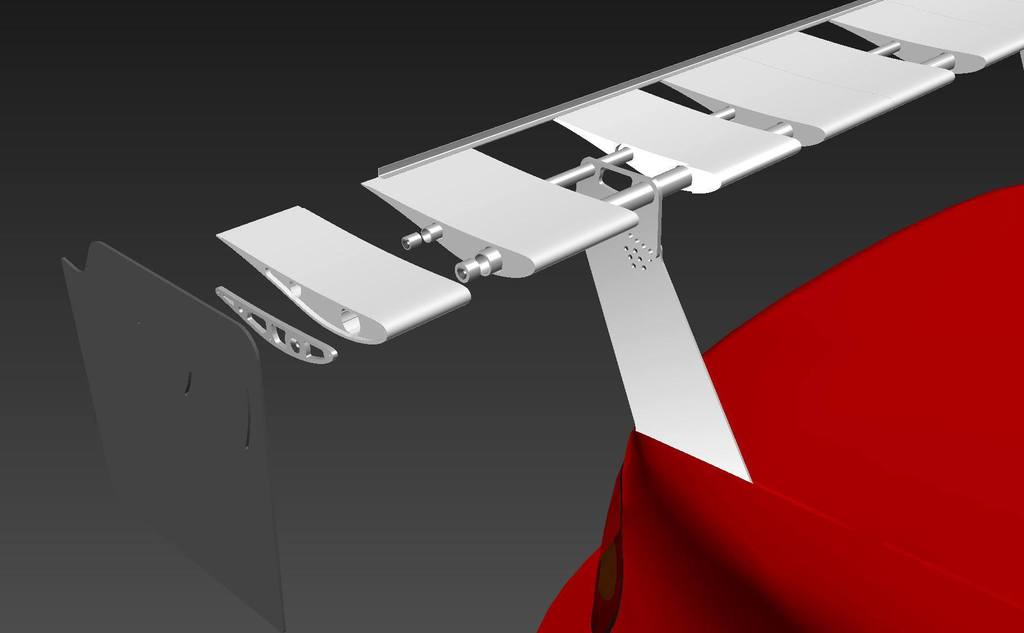
Print time for each section is around 10 hours, so a total of approx 110 hours of printing. I managed to get nearly 2 completed each day so I printed all sections in a week.
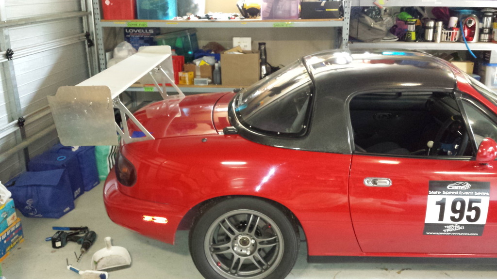
Here is a shot of it in parts getting assembled. The 12 plastic sections slot onto two ally rails that then get clamped at the ends with the brackets that mount the end plates. The main support brackets also slot onto the rails and are keyed into the plastic.
I have yet to test the wing at speed but it all feels pretty solid on the car other than a bit of sideways wobble. I think I might have cut too much metal out of the main vertical supports and will probably make some solid versions instead which should help the overall wing rigidity. The actual 3D parts have an internal honeycomb structure making them very strong but light. All up there is around 1.8kgs of plastic but next time I think I could reduce the infill even more to reduce weight and printing materials required.
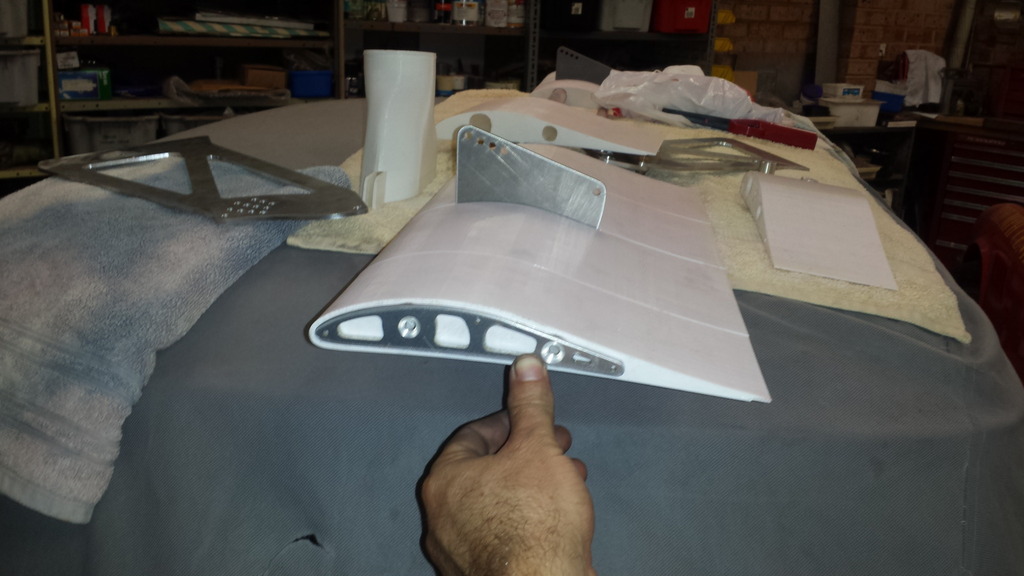
The photos below are the first install. I'll add a gurney / wickerbill which is a 10 x 10 mm ally angle and also angle the wing a bit more for my first test.

The endplates are a similar design to what Ryan (ThePass) has made for the COT wing. They are a little smaller and the angles are based on my wing profile so I hope I got the concept correct. Thanks Ryan for inspiring me to develop DIY aero!
The initial 3D design breakdown:
Print time for each section is around 10 hours, so a total of approx 110 hours of printing. I managed to get nearly 2 completed each day so I printed all sections in a week.
Here is a shot of it in parts getting assembled. The 12 plastic sections slot onto two ally rails that then get clamped at the ends with the brackets that mount the end plates. The main support brackets also slot onto the rails and are keyed into the plastic.
I have yet to test the wing at speed but it all feels pretty solid on the car other than a bit of sideways wobble. I think I might have cut too much metal out of the main vertical supports and will probably make some solid versions instead which should help the overall wing rigidity. The actual 3D parts have an internal honeycomb structure making them very strong but light. All up there is around 1.8kgs of plastic but next time I think I could reduce the infill even more to reduce weight and printing materials required.
The photos below are the first install. I'll add a gurney / wickerbill which is a 10 x 10 mm ally angle and also angle the wing a bit more for my first test.
The endplates are a similar design to what Ryan (ThePass) has made for the COT wing. They are a little smaller and the angles are based on my wing profile so I hope I got the concept correct. Thanks Ryan for inspiring me to develop DIY aero!
Last edited by Madjak; Apr 14, 2015 at 02:16 AM.
Reply
0
0

Yikes. What does that entire assembly weigh without the uprights?
__________________


Reply
0
0
ʎpunq qoq
Joined: Jan 2014
Posts: 604
Total Cats: 202
From: Western Australia
I haven't weighted it yet but it's very light. I could easily hold it in position with one hand whilst drilling the mounting holes in the boot. I think the ally would be 2kgs so around 3.5kgs total. I'm not that calibrated to weight so I'd have to weight it properly to know.
For reference, how heavy are the APR GT250 wings?
For reference, how heavy are the APR GT250 wings?
Reply
0
0
I haven't weighted it yet but it's very light. I could easily hold it in position with one hand whilst drilling the mounting holes in the boot. I think the ally would be 2kgs so around 3.5kgs total. I'm not that calibrated to weight so I'd have to weight it properly to know.
For reference, how heavy are the APR GT250 wings?
For reference, how heavy are the APR GT250 wings?
__________________
Reply
0
0
ʎpunq qoq
Joined: Jan 2014
Posts: 604
Total Cats: 202
From: Western Australia
Reply
0
0
ʎpunq qoq
Joined: Jan 2014
Posts: 604
Total Cats: 202
From: Western Australia
I have my CAD profiles somewhere and can load up the NACA profile vs the COT profile vs mine... I've just had a computer rebuild so I'll have to retrieve them off my old drive.
Does anyone have a photo of the APR GT250 wing without endplates? I think my wing should be pretty close to that design. I was looking for one when designing the profile and I don't think I ever found one.
Reply
0
0
ʎpunq qoq
Joined: Jan 2014
Posts: 604
Total Cats: 202
From: Western Australia
They are hosted on Box.com (similar to dropbox) with a public share. I need to get my act together and register for an online photo host. Maybe you have a firewall that blocking your access.
EDIT: Uploaded the images to a photo site and they should now work better... I hope
EDIT: Uploaded the images to a photo site and they should now work better... I hope
Last edited by Madjak; Apr 14, 2015 at 02:17 AM.
Reply
0
0


__________________
Reply
1
1
Joined: Apr 2014
Posts: 18,643
Total Cats: 1,870
From: Beaverton, USA

Reply
0
0

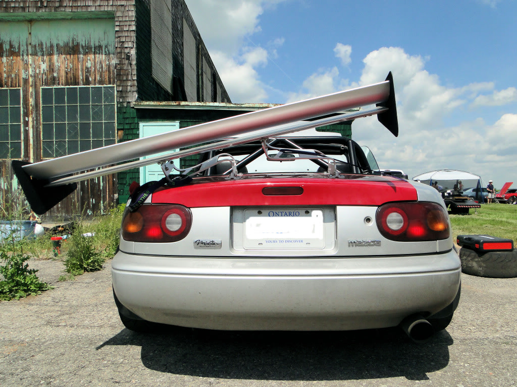
If you layed those two aluminum tubes across the uprights and put a 300lb distributed load on them, they would deform dramatically. That's exactly what you're doing at 120mph. Likely more force, actually.
Reply
0
0


