

Quaife Sequential for NA & NB


Joined: Apr 2014
Posts: 18,643
Total Cats: 1,870
From: Beaverton, USA
Not natively, no drive by wire support. You could maybe hook up some sort of setup to blip the throttle on clutch input. You would need something to mechanically pull the cable though.
Reply
 0
0

0

I ordered the geartronics load cel embedded in a shift **** in the 1/2" Quaife size. That voltages will trigger ign cut. Having driven dog boxes, you can just left foot brake, blipping while downshifting. The load cell will cut ign but I think it won't be needed on downshifts so much. We'll see if it works. I don't want to have to build a DBW system for it. Anyway, most cars running the QBE60G are not DBW and they work just fine.
__________________


Reply
0
0


What does one do about the PPF mounts. Does it have something for them that I don't see it in the pics on their site, do you ditch it, fab something, or ???? Just curious. Guess I'll have to see what Emilio does on OGK.
Reply
0
0
Dunno yet. Based on the drawings, we will have to fabricate a mount adapter.
The Quaife kit only addresses the trans adaption and shifter location, not the PPF mounts. We want to keep the PPF but are toying with the idea of ditching it. Of course we would then have to engineer and fab new trans and diff mounts.
The Quaife kit only addresses the trans adaption and shifter location, not the PPF mounts. We want to keep the PPF but are toying with the idea of ditching it. Of course we would then have to engineer and fab new trans and diff mounts.
__________________
Reply
0
0


Thread Starter
Senior Member
iTrader: (6)
Joined: Jun 2010
Posts: 1,421
Total Cats: 95
From: San Rafael, CA
I like the idea of keeping the PPF. I also like the idea of adding a trans brace. I feel confident Terry at Altered Acceleration will whip something really cool up for me.
Can't wait to pull the trigger on this!!!
Can't wait to pull the trigger on this!!!
Reply
0
0
Little update
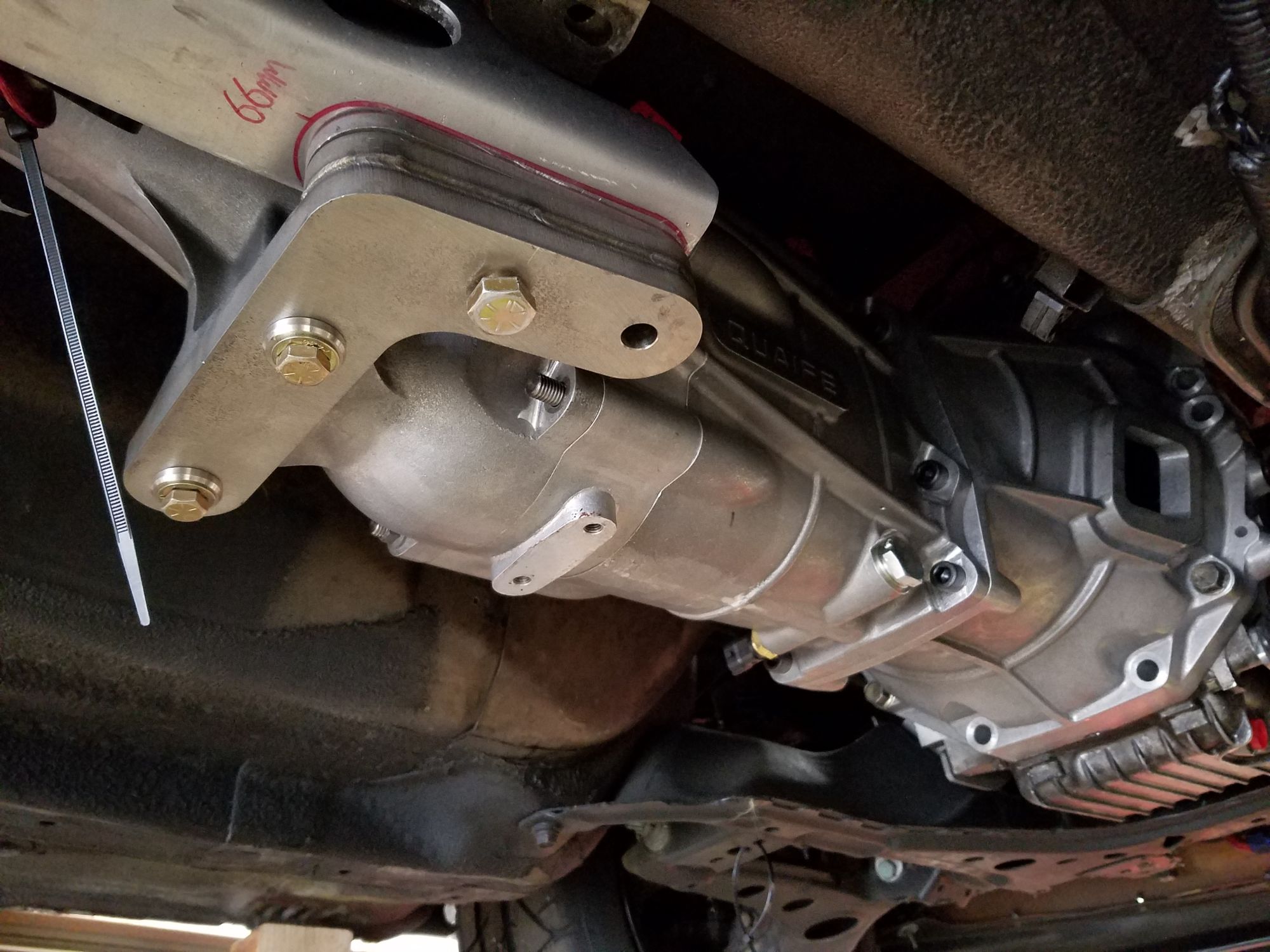
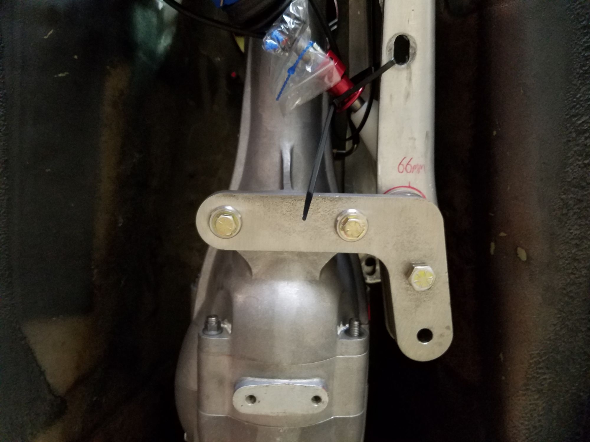
Top of case was a bit too tall to fit within PPF and also too tall to fit in tunnel. We set PPF height per FSM procedure on OEM trans then measured output shaft centerline relative to the tub. Idea was to put Quaife output shaft in exactly the same spot as OEM. Matching output shaft heights meant cutting about a 26 x 6" strip of the tub out forward of the shifter port. That wasn't happening so we deciding to check u joint angles and delta between the two with the Quaife lowered enough to clear the tub. We hoped it would still fall within acceptable range. Measured pinion angle relative to ground then output shaft. They were within .2�. Total angle of DS was right near zero
For those not familiar, it's nice too have a u joint angle below about 7� if possible, although rock crawlers and lifted 4Xs run as high as 20�. More importantly, you want whatever angle the DS leaves the trans to be matched on the diff end within about 1�. Google that but basically, the u joint tip changes its speed as it spins around because of an elliptical path. U joints being offset 90� will cancel those speed differentials out provided the two sine waves are the same pitch & amplitude. So.. OEM is under 3� DS angle and under 1� delta between the two, ours is closer to .5� so basically a straight shot from trans to diff. So no hacking out of tub, phew. Should have the PPF adapter thing built in a few days. We'll post pics.
__________________
Reply
0
0
Little update
Top of case was a bit too tall to fit within PPF and also too tall to fit in tunnel. We set PPF height per FSM procedure on OEM trans then measured output shaft centerline relative to the tub. Idea was to put Quaife output shaft in exactly the same spot as OEM. Matching output shaft heights meant cutting about a 26 x 6" strip of the tub out forward of the shifter port. That wasn't happening so we deciding to check u joint angles and delta between the two with the Quaife lowered enough to clear the tub. We hoped it would still fall within acceptable range. Measured pinion angle relative to ground then output shaft. They were within .2�. Total angle of DS was right near zero
For those not familiar, it's nice too have a u joint angle below about 7� if possible, although rock crawlers and lifted 4Xs run as high as 20�. More importantly, you want whatever angle the DS leaves the trans to be matched on the diff end within about 1�. Google that but basically, the u joint tip changes its speed as it spins around because of an elliptical path. U joints being offset 90� will cancel those speed differentials out provided the two sine waves are the same pitch & amplitude. So.. OEM is under 3� DS angle and under 1� delta between the two, ours is closer to .5� so basically a straight shot from trans to diff. So no hacking out of tub, phew. Should have the PPF adapter thing built in a few days. We'll post pics.
Reply
0
0
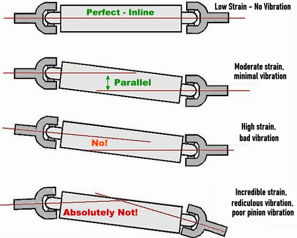
Driveshaft is our standard Miata. We are close to zero-zero, the top example. All is good.
__________________
Reply
0
0
I've always heard that dead zero angles will eat the U-joints since the needles never move.
Move the engine+trans a little towards the passenger side? The parallelism can be in any direction
Move the engine+trans a little towards the passenger side? The parallelism can be in any direction
Reply
0
0
Reply
0
0

Joined: Sep 2005
Posts: 34,433
Total Cats: 7,549
From: Chicago. (The less-murder part.)
I'd never even thought about this before, and was having a hard time visualizing it. But having watched the video, it makes perfect sense.
I feel like an utter moron. An enlightened moron, but a moron none the less.
Reply
0
0
By pure dumb luck we ended up just off zero for the drive shaft angle and right at zero for the included angle. We're going to measure once it's all mocked up again to make sure our DS is not exactly at zero.
On a related note for anyone with mysterious driveline vibrations, set your PPF height according to the FSM and compensate for crunched frames rails (they're the reference).
On a related note for anyone with mysterious driveline vibrations, set your PPF height according to the FSM and compensate for crunched frames rails (they're the reference).
__________________
Reply
0
0
By pure dumb luck we ended up just off zero for the drive shaft angle and right at zero for the included angle. We're going to measure once it's all mocked up again to make sure our DS is not exactly at zero.
On a related note for anyone with mysterious driveline vibrations, set your PPF height according to the FSM and compensate for crunched frames rails (they're the reference).
On a related note for anyone with mysterious driveline vibrations, set your PPF height according to the FSM and compensate for crunched frames rails (they're the reference).
Reply
0
0
So we learned something interesting about the NA/NB while measuring our final driveshaft position. Our target parallel angle was 1� which is where we are. While measuring it, we noticed the OEM NA/NB driveshaft angle is 1� laterally. Looking forward form diff, the shaft angles towards pax side just a bit. Not sure if the diff mounts are angled, or the diff casting is asymetric. Looks like the OEM shaft is actually 0� vertically but right at the ideal 1� laterally. We ended up with that same lateral offset as well.
__________________
Reply
0
0


