

Splitter Height


We locate our ducts as close to the car centerline as possible for this reason. They can also be located in the bumper opening for the rad. The air is all but stopped here but is significantly higher pressure than the backside of the rotor. In this example the differential moves air down the duct tube for you.
__________________


Reply
 0
0

0

Senior Member
Joined: Dec 2010
Posts: 993
Total Cats: 57
From: Auckland, NZ
I have just made v1 of a nose undertray/flat bottom and need to add extensions out to the wheels from the initial middle section.
Unfrotunately I overestimated the required wheel and tyre clearance and need to add extensions on each side..
But, how close should I get to the wheels/tyres? ( on the sides i.e by the lower control arms) and in front of the tyre, do people extend the tray deeper than the wheel arch, towards the tyre...?
As close as possible or it doesn't matter too much in this turbulent area.....?
Some intersting results on my first drive with this v1 middle section....yet to be decided conclusively but the gearbox tunnel seems to be considerably cooler (as compared with no engine undertray where the gear box tunnel was almost to hot to touch...56+ deg C)
My slight front crank seal oil leak appears to be blowing out the back and not dripping straight down the front of the engine like it used too.....(inside the tray is spotless despite a 60km test drive whereas I have oils spots all over my drive from the persistant leak previousley.....)
So, while I haven't had time to prove either point conclusively it would appear the flat tray has raised the air flow or suction out of the engine bay considerably...is this likely to that extent?
And is the reduced tunnel temp likely or do you guys think I am probably imagining it?
Reply
0
0

The general assumption is that the undertray would trap engine and exhaust heat so it is very interesting if you feel it is actually sucking the heat out. Do you have an extraction hood or any other topside vents in front of the firewall? At a glance, they would appear to lower the pressure/velocity/volume of air rushing through the tunnel even though they help the heat exchangers.
Maybe a functional approach when coolant temps isn't the absolute priority (i.e. no 100*f ambient racing, WHP<250, etc.) is to have high pressure at the front, medium pressure in the engine bay and low pressure where the tunnel exits past the diff.
Reply
0
0
Senior Member
Joined: Dec 2010
Posts: 993
Total Cats: 57
From: Auckland, NZ
Just for the record, I do run FM bonnet louvres and the undertray on this car is just to the normal mounts behind the steering rack.
Without any front tray the tunnel temps were so bad I had ordered some reasonably expensive heat mat for under the car inside the tunnel but now it looks like I may not need it.....
That would be good. Although all bets are off if I move from 10 to 14lbs boost I guess....
Anyway, I love this thread, great info. Just thought I would contribute my tidbit.
Reply
0
0

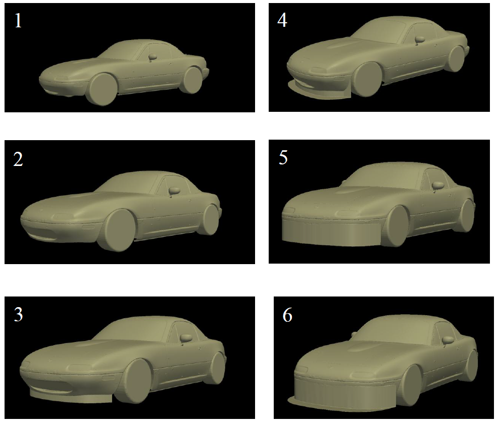
Since this is about front splitters and air dams, I will leave the info I have gathered with miatas using cfd. This is a watered down version 
1. Stock 1990-1997 Mazda Miata
2. Stock 1990-1997 Mazda Miata at a 4in Ride Height
3. Small Front Air Dam at 4in Ride Height
4. Small Air Dam with Splitter at 4 in Ride Height
5. Large Air Dam at 4in Ride Height
6. Large Air Dam with Splitter at 4in Ride Height
Note: The air dam and/or splitter is 2 inches off the ground in study 3-6
CFD Models
The solver used for these analysis is a steady state incompressible solver with a k-omega SST turbulence model.
Data
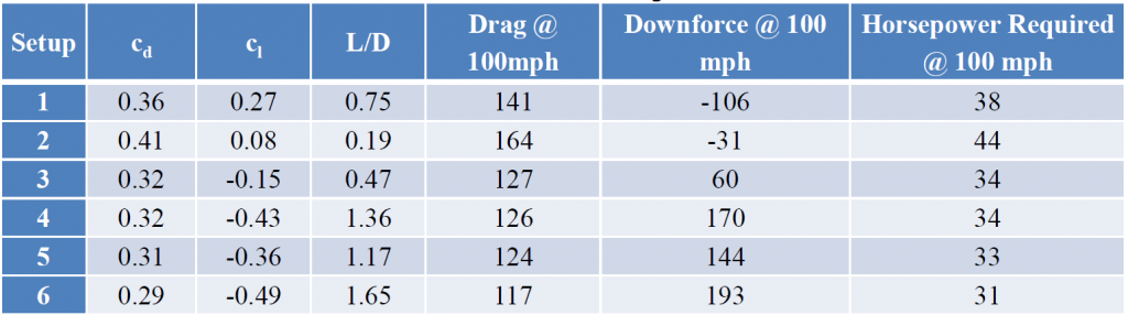
Cd = coefficient of drag
Cl = coefficient of lift
L/D = lift divided by drag / aerodynamic efficiency
1. Stock 1990-1997 Mazda Miata
2. Stock 1990-1997 Mazda Miata at a 4in Ride Height
3. Small Front Air Dam at 4in Ride Height
4. Small Air Dam with Splitter at 4 in Ride Height
5. Large Air Dam at 4in Ride Height
6. Large Air Dam with Splitter at 4in Ride Height
Note: The air dam and/or splitter is 2 inches off the ground in study 3-6
CFD Models
The solver used for these analysis is a steady state incompressible solver with a k-omega SST turbulence model.
Data
Cd = coefficient of drag
Cl = coefficient of lift
L/D = lift divided by drag / aerodynamic efficiency
One main thing I wanted to achieve with these cfd runs was to compare options 4-6. Obviously these options are what most people in the miata community are running.
A few months ago there was a thread where someone explicitly asked what was better option 4 or 5. When I suggested that 4 (my current car) would make more downforce, someone suggested that wasn't true because option 5 reduced lift and the net change would be more downforce than option 4. Obviously these results show that is not the case and prove me right, huzzah!
But seriously I'm glad we were able to get this model together and quantify some things in regards to miata aerodynamics. I would also like to echo Emilio's comments in regards to the curse of the internet. Couldn't have put it better myself.
Reply
0
0
Reply
0
0

Junior Member
Joined: Mar 2009
Posts: 62
Total Cats: -5
From: Eastern US
No induced drag, or only induced drag? Your CFD model seems to be calculating Base drag. What about parasite and rotating wheel drag? I venture to say that it is quite significant on these little cars. And what about drag during side slip? As in 4-12% lateral angle of attack for maximum tire grip?
I love this topic and the analysis which is why it peaked my curiosity? Does any other forum go to this level of detail to analyze and improve their car?
I love this topic and the analysis which is why it peaked my curiosity? Does any other forum go to this level of detail to analyze and improve their car?
Reply
0
0
Junior Member
Joined: Mar 2009
Posts: 62
Total Cats: -5
From: Eastern US
For most MT dot net lurkers, hydrodynamics trumps aerodynamics (sex-wise) and incompressible fluids mark their passion. I for one, find as much joy in compressible fluids as in incompressible.

Reply
0
0
Are you asking about the effects of yaw? I'm sure if you pay Paul enough he will run it at whatever yaw angle you are curious about.
What do you mean by this?
What do you mean by this?
Reply
0
0

Newb
Joined: Jun 2012
Posts: 17
Total Cats: 0
From: Zionsville, Indiana
Something I didn't notice any one talking about is the use of a Gurney Flap at the trailing edge of the air dam to scavenge even more air from the area in front of the tire, it will increase drag a little but it's really worth it for downforce gain.
If reducing CD was the goal just fair the wheels, make the bottom smooth, and allow the air to flow smoothly to the bottom by rounding the radius of the bottom leading edge. (this also reduces total frontal area)
Reply
0
0

Senior Member
Joined: Oct 2011
Posts: 646
Total Cats: 62
From: The Race Track & St Pete FL
I'm doing my front end aero and since we are on the subject. I was looking around on the net to see what kind of canards there are for the NA. I remember seeing the Brightning, but their pictures suck(Brightning Front Canards For Miata MX5 MX-5 89-97 JDM Roadster : REV9 Autosport). Does anyone know of a better pic? I'm going to make my own out of pre-preg and searching for ideas.
Reply
0
0

Junior Member
Joined: Dec 2012
Posts: 74
Total Cats: 45
From: Indianapolis
No induced drag, or only induced drag? Your CFD model seems to be calculating Base drag. What about parasite and rotating wheel drag? I venture to say that it is quite significant on these little cars. And what about drag during side slip? As in 4-12% lateral angle of attack for maximum tire grip?
I love this topic and the analysis which is why it peaked my curiosity? Does any other forum go to this level of detail to analyze and improve their car?
I love this topic and the analysis which is why it peaked my curiosity? Does any other forum go to this level of detail to analyze and improve their car?
Induced drag is drag that occurs or induced when a moving object redirects the airflow moving around it. It is usually referring to wings... It is inversely proportional to velocity.
Base drag is.... I have never heard of it
Parasitic drag is pressure drag and friction drag and increases proportionally to the square of the velocity.
Rotating wheel drag? I understand this...but what do you mean?
The drag that is calculated in my analysis is total drag.
Total Drag = Friction Drag + Pressure Drag + Induced Drag
Are you talking about yaw for the last part? I really do not understand.
Reply
1
1
Two of his questions as I understood them were:
a) what about cases where airflow is not directly head on, but is yawed horizontally at an angle of between say 4 to 12 degrees. I'm not entirely positive as to the value of this. Having airflow yawed at a static angle is a poor approximation of simulating the car during a turn.
b) rotating wheel drag - he wants to know if your model is assuming stationary wheels, or if some function is being used to approximate the different drag created by wheels that are rotating. I believe you said earlier that your model uses a moving floor, correct?
Reply
0
0
Reply
0
0
Junior Member
Joined: Dec 2012
Posts: 74
Total Cats: 45
From: Indianapolis
Two of his questions as I understood them were:
a) what about cases where airflow is not directly head on, but is yawed horizontally at an angle of between say 4 to 12 degrees. I'm not entirely positive as to the value of this. Having airflow yawed at a static angle is a poor approximation of simulating the car during a turn.
b) rotating wheel drag - he wants to know if your model is assuming stationary wheels, or if some function is being used to approximate the different drag created by wheels that are rotating. I believe you said earlier that your model uses a moving floor, correct?
a) what about cases where airflow is not directly head on, but is yawed horizontally at an angle of between say 4 to 12 degrees. I'm not entirely positive as to the value of this. Having airflow yawed at a static angle is a poor approximation of simulating the car during a turn.
b) rotating wheel drag - he wants to know if your model is assuming stationary wheels, or if some function is being used to approximate the different drag created by wheels that are rotating. I believe you said earlier that your model uses a moving floor, correct?
). Yawing the airfow/car was the way to simulate turns and still is for windtunnels. However now with cfd, you can actually flow the air in a radius to simulate a corner situation. The big guys in motorsports are doing this (not really useful in this level of motorsports imo). Not directed towards you as you were just clarifying somebody else's post.

This
Reply
0
0


What do you guys think about the kazespec splitter mounting kit?
KazeSpec Engineering FULL Aero Kits!!!! - Page 11 - ClubRoadster.net
KazeSpec Engineering FULL Aero Kits!!!! - Page 11 - ClubRoadster.net
Reply
0
0


