When you click on links to various merchants on this site and make a purchase, this can result in this site earning a commission. Affiliate programs and affiliations include, but are not limited to, the eBay Partner Network.
Mind you, I had two grand goals I wanted to accomplish in one go: Replace both the gearbox and the diff with BMW units while maintaining the PPF, AND getting the car painted because the previous paint ordeal turned out to be a hack job, and the body was going to rust under the delaminating primer coat.
So I thought the best way to tackle the project would be to separate the body from the skateboard and just send it away. BASF Turkiye was sponsoring the body and paintwork.
Anyway.
I made a list.
I knew I would be adding to the list as work progressed, because there were quite a few things I wanted to get out of the way once the car was apart to that extent.
That part got a bit out of hand actually. I ended up removing everything. There was surface rust on the cross member inside the dash, for example. That had to be media blasted and powder coated.
All the wiring shenanigans had to be cleaned up, heater box had to be gone over, you get the picture.
I just hate it when a job is simple.
Next thing you know, the body was out of the way.
I made a point of securing the front and rear subframes together using square tubing so they would stay perfectly aligned for the surgery. I know the PPF keeps them together, but that was going to come out, too.
Once I had the skateboard clear in the open, I added two more pieces of square tubing to be safe.
The body had no wheels anymore. I quickly fabbed a caster wheel setup so it could roll around and be loaded on a flatbed tow truck.
I made sure the caster wheel setup was as high as possible so the paint guys would have an easier time working on the car.
(That proved to be a nightmare on the tow truck. We had to tie the car down like mad so it would not tip over on the freeway)
Anyway, I was able to take some surreal photos of an upside down Miata, too.
Safely delivered the body to the paint shop and proceeded to focus on the work at hand...
Last edited by Godless Commie; 01-02-2024 at 12:51 PM.
I had to start with an adapter plate for the BMW gearbox.
While I have access to some very accomplished industrial designers I wanted to start with the trusted old school methods and broke out the masking tape.
The adapter plate had to be dead on accurate, meaning, the trans input shaft had to be perfectly straight to avoid an untimely death of the poor gearbox.
So all my masking tape templates were carefully scanned and perfected on a couple different computers.
Then I had a 3 mm thick adapter plate laser cut from plexiglass, because it is cheap. That plexiglass prototype proved to be very useful. The input shaft was dead center indeed.
A good friend laser cut the actual adapter plate out of 5083+H111 aluminum. We decided it should be 20 mm thick to avoid any distortion issues down the line.
I immediately test fit the adapter plate
and the starter...
All looked good so far.
There was one problem: I wanted to use countersunk bolts to spread the load on the adapter plate. There are no M12x1.5 countersunk bolts available.
I could have them cut on a lathe, but that weakens the threads. Being the paranoid guy I am, I wanted them cold forged, or rolled, and they had to be either grade 12.9, or 10.9, depending on their use.
So I went to a bolt factory and talked to the manager very nicely. He agreed to stop production and make me a handful of bolts.
I bought some very long grade 12.9 and 10.9 bolts and they shortened them to my specs and went to work...
Engine and gearbox were united for the first time...
Although that was an accomplishment, the light at the end of the tunnel was too far away to see yet. There were a million hurdles to overcome.
What the hell was I going to do about the speedometer for example? Or, the PPF for that matter...
One thing at a time.
I had to cut the bellhousing to make the starter fit. That cut worried me. I mean, what if the damn thing started cracking, right?
I know this incredible welder. I left the gearbox with him for a day, and he did this:
This is poetry with a TIG torch as far as I am concerned.
My wife helped me load the engine, both transmissions and all the associated parts in a borrowed Ford station wagon, and we drove a couple hundred miles to Bursa to see a specialist.
That guy is good.
I initially wanted a twin plate organic clutch setup to avoid any hassles down the line. Gurdal (the specialist who is very good) took all the measurements and we returned home after a nice late lunch.
Sometime after that trip, I received a pretty heavy box:
6061-T6 Aluminum...
8.6 Kg
I was surprised to find a single plate, sintered bronze 6 puck clutch...
I mean, the car would be a nightmare to drive.
Gurdal assured me it would be just like driving a full face organic setup, and slipping this clutch would be well beyond my car's capabilities.
He just said I could almost triple my current torque and this clutch would not slip.
Guess what.. He is right. It is very smooth, there is no herky jerky engagement, and all is cool...
Oh, remember the custom bolts?
Grade 12.9 M12x1.0 Allen head flywheel bolts!
I also had that nifty stainless steel washer laser cut so the bolt heads would not hurt the aluminum.
With the flywheel and the clutch out of the way, it was time to focus on a driveshaft...
I talked to a bunch of people who basically said "measure that there distance between the tranny and the diff and we'll bang one out for ya"...
Finally, one guy asked me very specific technical questions about what I needed. I went to him.
Pretty big manufacturing plant. They make driveshafts anywhere from the size of a ball point pen to 4 foot diameter, 60 foot long behemoths..
We sat down by the computer and came up with a design that is light and yet manly enough to handle 1600 nm.
I had the gearbox and the dummy diff with me along with all the necessary measurements, and they made me a beautiful driveshaft (balanced and everything) while we had a couple cups of tea..
They even made a 3 bolt flange so I would not need an adapter.
They had this one ready to go, but I had a feeling it would not fit my car...
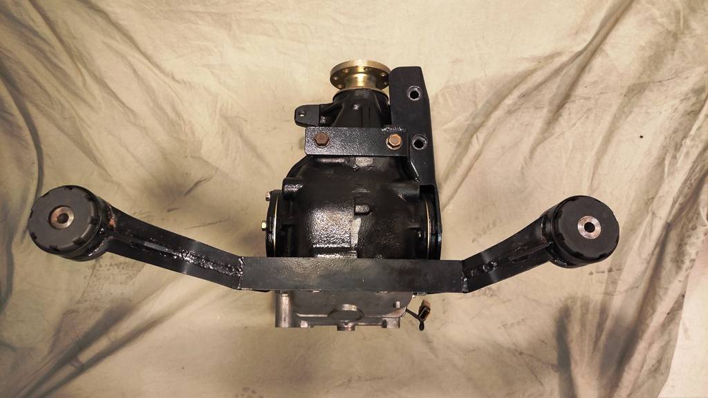
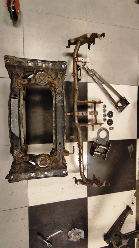
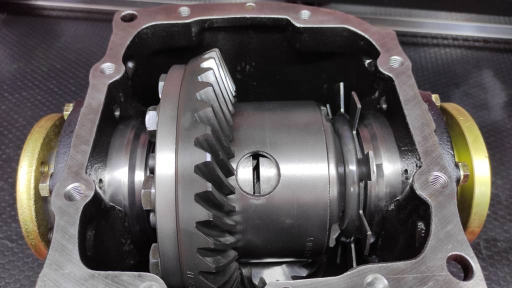
All I had to work with was a dummy diff at this point. I had paid for a pretty robust unit, and it was just a matter of time for the diff to be custom built.
I had decided on a E30 M5 LSD diff with 3.15:1 gears. The clutch pack would be adjusted for my car's weight, with a "1.5 way" limited slip setup.
The guy who built the diff turned out to be pretty questionable character. It took about 8 months to finally receive the diff, and I had problems with it.
First time I laid eyes on the diff...
And, later on...
Fast forward a bit:
The diff whined LOUDLY at anything over 50 mph, so it had to be redone with new gears. Version 2 whined as well.
We went for version 3, and this time I wanted a 3.07:1 ratio.
The 3.07 ratio worked out to be a much better solution in terms of gearing and overall driving experience. I mean, I was able to spin the tires at 4th with the 3.15 setup. Much more controllable now.
For the record, these posts are not in chronological order. I was tackling multiple parts and issues simultaneously, and if I were to tell the story of this adventure in real time, it would be a confusing mess.
Going chapter by chapter ensures some level of sanity here.
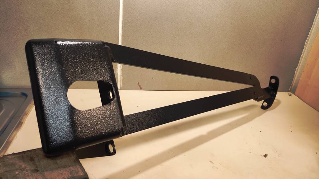
I had to find a way to mount this thing in the rear subframe.
While I was researching PPF solutions, torque tubes and various torque arms to harness the diff, I had looked into all kinds of practical solutions.
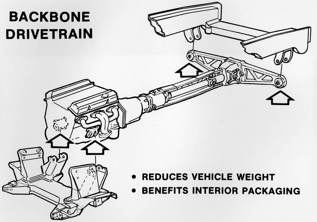
One design made more sense than the rest for me. The C4 Corvette.
Not only the C4 utilizes a PPF, but it uses a batwing design to hang the diff between the rear axles.
Basically, this:
I had no intentions of fabbing a whole rear cover like that. The best solution would be making a batwing, and sandwiching it between the diff and the cover.
I started with simple materials laying around the garage.
Polycarbonate is a wonderful material to work with. You can bend it using a hammer, drill it, rivet it, do anything you like, it does not crack. It's like transparent aluminum.
So I roughed it out of a few scrap sheets of polycarbonate glued together.
Since this diff is visibly heftier than the stock diff, routing the exhaust would be a problem. And, I wanted a 76 mm exhaust all the way to the back.
If only the diff could get out of the way.
Actually, it could.
I had this weird idea to maybe mount it off to the passenger side by 25 mm. I mean, driveshafts work at ungodly vertical angles, what's a 25 mm offset to the side over 108 Cm, right?
But then, this would mean unequal length rear axles. Would that create a problem?
My physics and mechanical knowledge said it would not create problems, but I had to make sure.
I sent emails to Dyson Racing, Penske Racing, Red Bull F1 team, Koenigsegg, several auto manufacturers and speed shops, asking specific questions about rear end behavior under heavy loads, torque delivery and whatnot.
Koenigsegg responded and they basically said they have very important things to do rather than wasting their precious time on the doe eyed aspirations of some commoner.
I finally had a very pleasant phone conversation with the R&D director of AVITAS, a company that designs and builds race cars for a couple racing series in Europe. Turns out I was not wrong or stupid. Good to know.
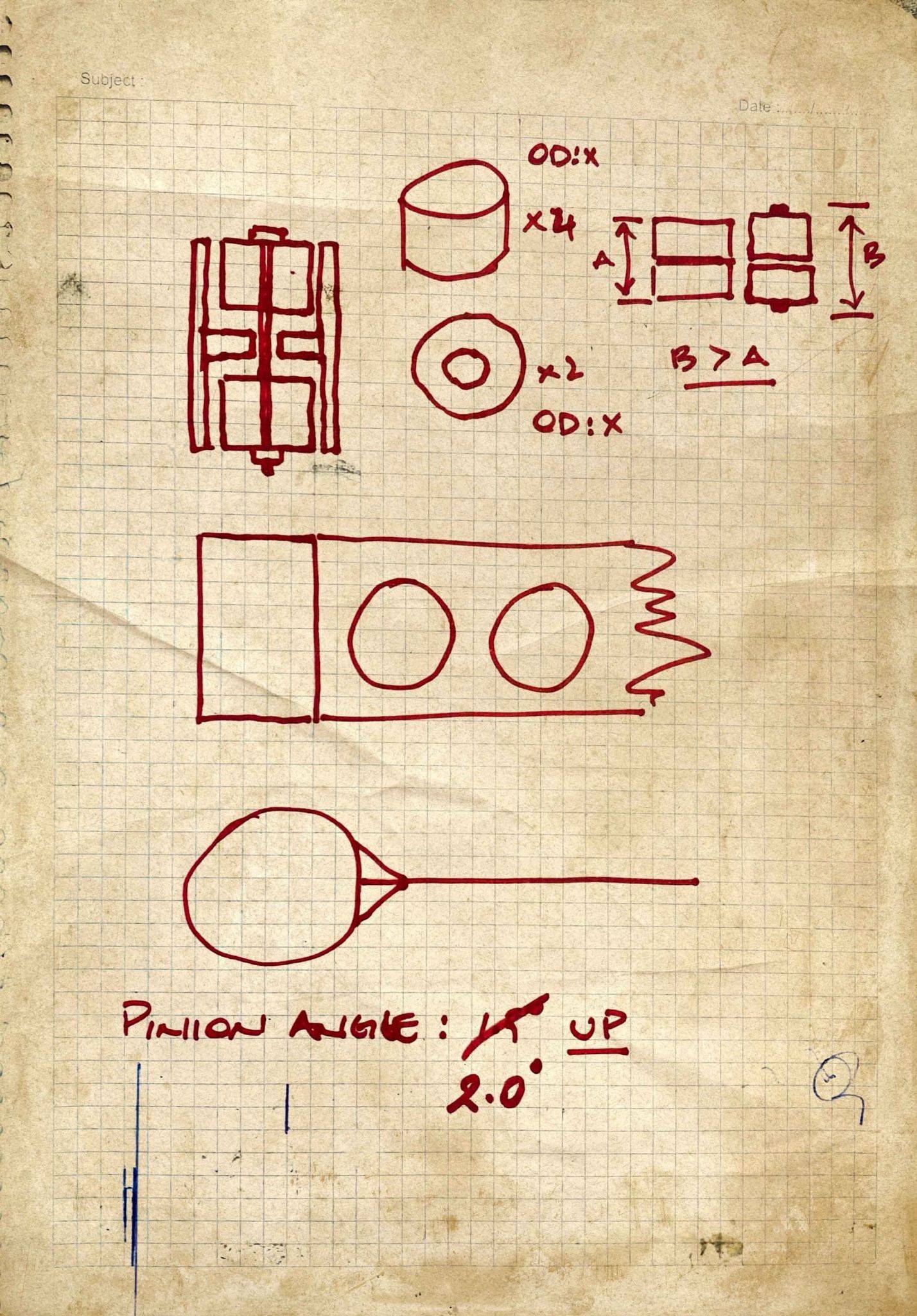
OK... Mount the diff 25 mm offset to the passenger side, but do that with as much precision as possible. I set myself a tolerance limit of 0.1 mm and 0.1 degrees.
Deciding on the rough location of the diff took a day. Dialing it in with the tolerances I had set took over 3 weeks and most of my knowledge of geometry to measure the said tolerances.
Once I located the diff, I made a second prototype out of MDF:
I took a bunch of additional measurements, jotted down a ton of notes and took the design to a friend who helped me transform it into a meaningful project file on the screen:
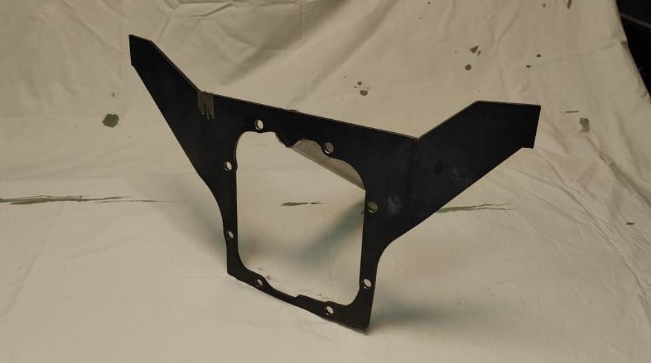
Once we were satisfied with what we had, it was time for a final prototype out of 4 mm steel. Off to laser cutting...
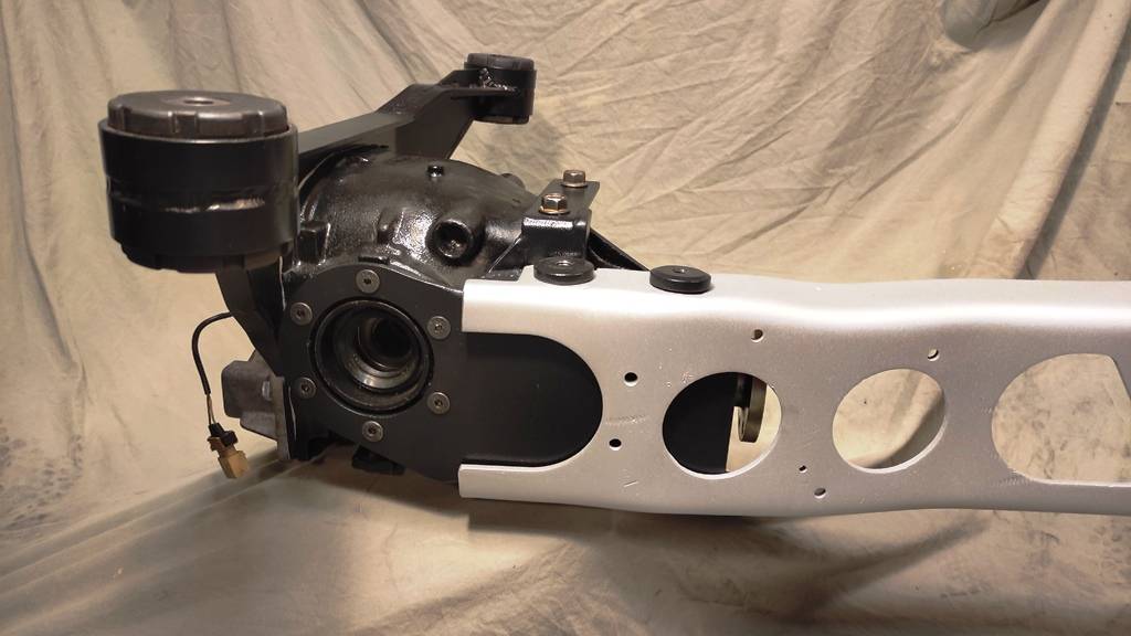
I was really happy with the outcome, but there was still the matter of attaching this thing to the subframe.
I wanted a real bushing solution, meaning, a strong connection with no metal to metal contact. NVH is a a savage beast that makes you hate your car in short order.
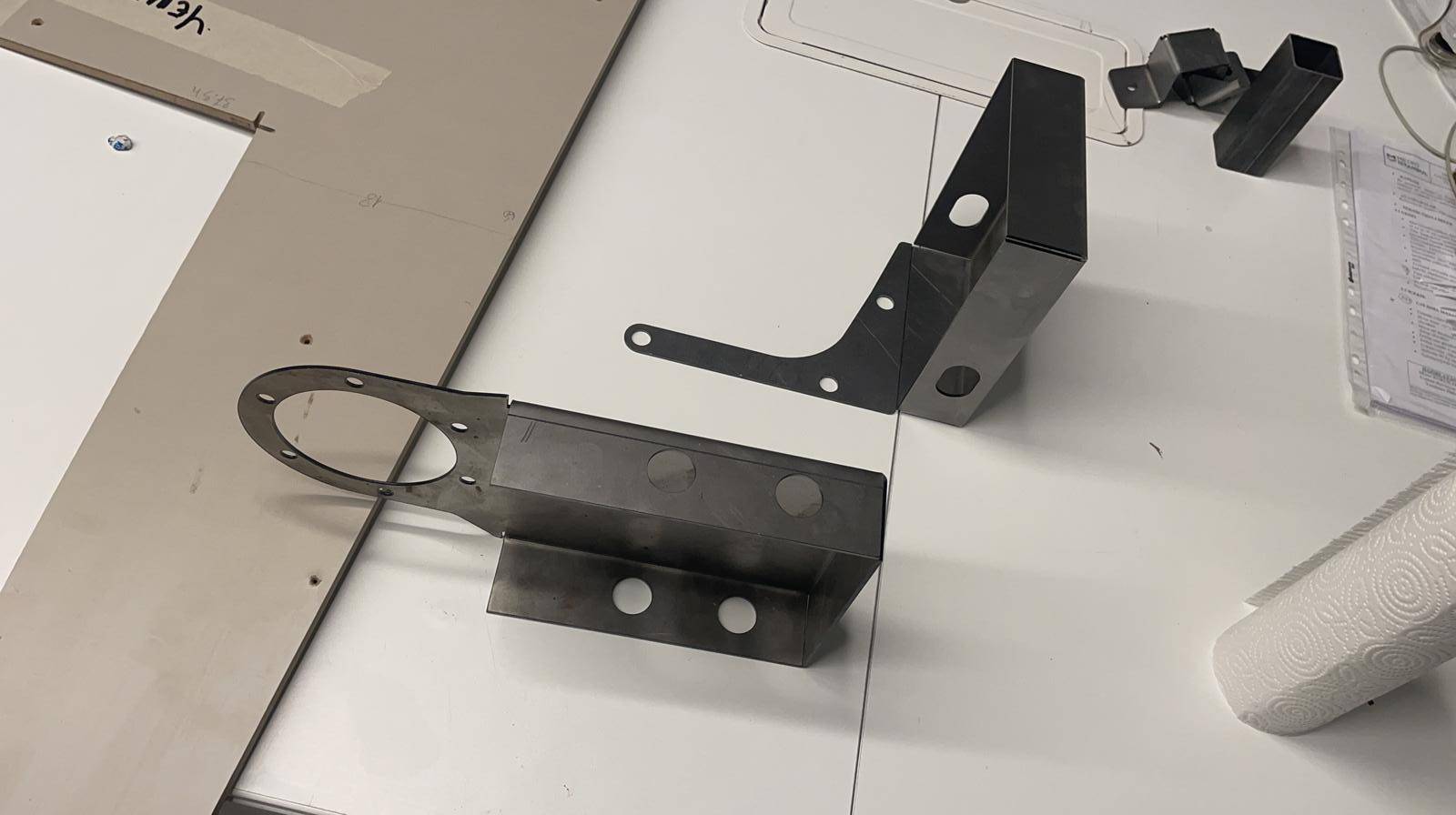
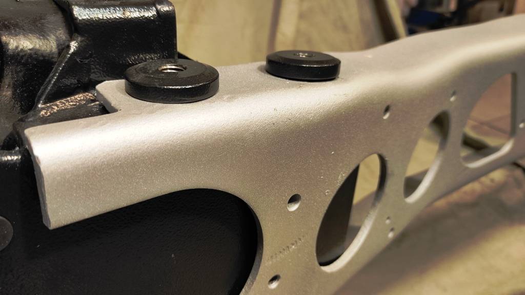
So, I came up with several ideas, and picked the simplest one. I would use a total of 4 rubber bushings, 2 on either side, sharing a common sleeve.
Went into producing the bushing brackets at full speed:
With the brackets done, I really took my time to locate everything as precise as possible, and prepared the batwing for welding.
Serious reinforcements were added for good measure.
The end result was just perfect. No warpage, no deviation, just perfect.
I am still using the dummy open diff for fitting purposes at this stage.
A major hurdle was in my rearview mirror now. The diff could and did fit in the subframe.
I now had to concentrate on that sizable gap between the gearbox and the diff.
My goal from the very beginning was to have some sort of a PPF setup rather than bolting the diff nose to the subframe.
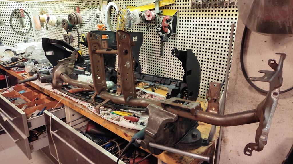
I did a lot of reading on the subject, did a ton of head scratching, and thought the best solution would be fabricating a custom PPF out of chromoly tubing with flat steel bars at either end to pass the long bolts through.
The stock PPF was too long, and I honestly did not give it much chance to survive the additional torque from the TWO turbos hanging off the engine.
I looked into drag cars, street builds and hi power setups that utilized a torque arm, and searched for ideas.
Then I remembered the C4 Corvette...
I faintly recalled some production car speed record deal back in the late 80s.
The Callaway Sledgehammer! That car hit 255 mph with a 880+ Hp custom built engine.
It took a while, but I was able to find a grainy video of that car on a lift before or after one of its many runs. The damn thing still had its original aluminum PPF!
What's good for a monster Corvette should be good for my car, right?
I immediately ditched all other ideas and started looking into making the stock PPF fit in my new setup.
My go to material seems to be polycarbonate when I am thinking in 3D...
Such weird ideas eventually turned into proper computer drawings:
Which produced 1.5 mm steel prototypes for rehearsing..
I was happily fitting the PPF into a non-existent car!
The body was away, being restored and painted. I had no way of verifying whether or not turbo hit block.
I mean, the PPF follows the contours of the body. Locating it incorrectly would mean disaster.
So, I removed everything and installed the stock diff and gearbox in the skateboard. I then installed the PPF, and very carefully plotted its position in space (x, y and z coordinates) in several spots.
Reinstalled the BMW parts, positioned the PPF where it should be, and then started taking measurements for attachment points, angles, how much I should shorten the PPF, etc.
Painful, slow and painful and slow work. It was painful.
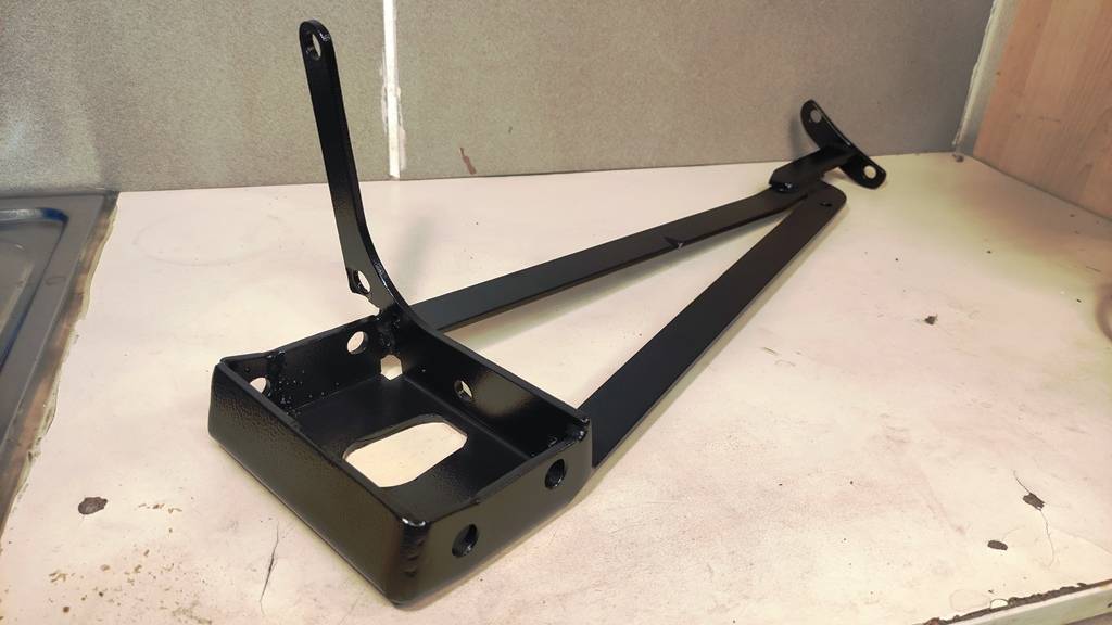
It started coming together. The PPF adapter for the diff turned out to be very strong, and there were more than plenty attachment points to distribute the loads.
Mazda has a very good design where they use threaded plugs for the PPF bolts to avoid stressing the aluminum, so I followed suit and made 4 large plugs to a) distribute the bolt loads, and, b) locate the PPF very accurately on the diff.
The front (gearbox side) PPF attachment point was a bit more straightforward, but it too had its own challenges. I wanted to distribute the load as much as possible to the strongest elements.
That is why I ended up with a weird looking cradle thingie that extends all the way to the bellhousing. I mean, the strongest part of the engine-tranny combo is the bellhousing bolts.
With almost all the hard parts sorted, it was time to take everything apart and get them media blasted and powder coated.
Getting such work done in places specializing in auto parts is pretty expensive. I found a pretty big plant media blasting and powder coating all kinds of stuff for the construction industry. I mean, HVAC systems, ducting, railings, kitchen hoods, you name it. They quoted me less than half of what the auto part restorers were asking, so I removed and got everything done.
Remember the crossbar in the dash with surface rust? Yes even that..
Feeling proud, I had to take some photos. Pleas allow me to indulge here:
Before I forget.. See those bushing sleeves in the first photo? I made those sleeves in three different sizes. That gave me a chance to alter the preload on the rubber bushings so I could make them softer or firmer. I was hoping to find a sweet spot where NVH would be eliminated without excessive diff movement.
I was able to achieve just that. Worked ilke a charm.
While I was waiting for the parts to be media blasted and powder coated, I attacked the "small stuff" I wanted to get done on the car.
Ignition coils needed to be upgraded. The Toyota COPs seemed to be crapping out at around 18 psi, so I went with iridium plugs and R8 coils...
And made a nifty coil holder thingie (and that was powder coated eventually)
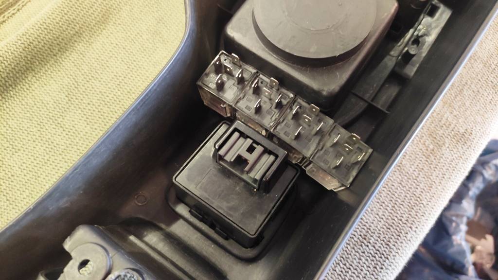
These coils draw some serious current. I could not entrust that to the car's 15A ignition circuit, so I added a 40A relay and used the ignition feed to trigger that relay. Safe.
*******************
All electric motors (window motors, blower fan motor, starter, alternator, water injection pump motor, etc) were taken to a specialist and rebuilt/renewed as needed.
*******************
I replaced the worn out steering rack with a reman unit TurboTim sent me. (Thanks again, Tim!)
********************
Finally installed the oil cooler I had on a shelf for a while.
********************
Made offset Delrin bushings for the FUCA to solve the limited front camber problem.
********************
Installed heavy gauge speaker wires for the 550 Watt speakers in the doors and the 500 Watt speakers in the rear shelf.
I am driving them with a Pioneer GM-A6704 amp.
********************
Upgraded the ignition driver circuit in my MS2 Enhanced to drive the R8 coils, also upgraded the MAP sensor with a 4 BAR unit.
********************
Cleaned up the wiring mess under the dash,
Added a programmable feature (with relays) to my gauge screen interface to drive the oil cooler fan, electric power steering pump, water injection shutoff solenoid and the active hood vent motor under the right conditions.
********************
Sorry I do not have photos for these steps. I usually worked at nights and just could not remember to take pics. My bad.
*******************
Oh, I also added a bank of relays to take the current load off the power window switches and drive the windows straight from the battery. They roll up and down much faster now.
Last edited by Godless Commie; 01-02-2024 at 09:32 AM.
I still had a ton of work to do..
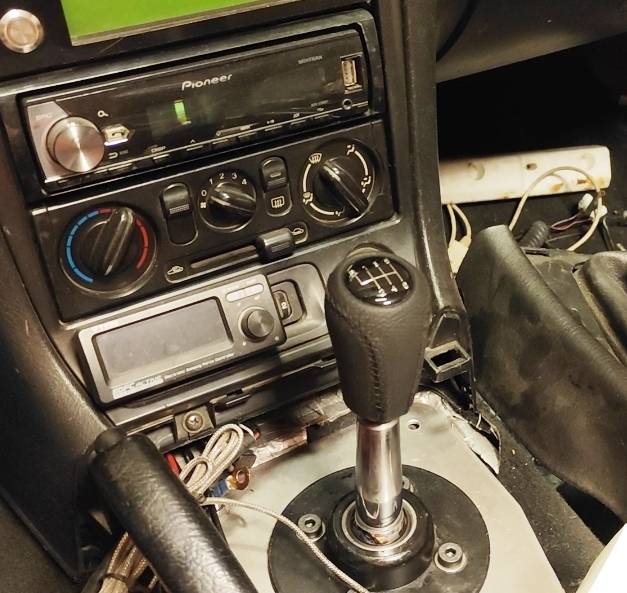
Working off my to do list, I moved on to the gear selector. The stick.
OEM BMW gear selector required a ton of cutting and fab work. And, they are known to develop a lot of slack.
So, I went with the next best option and ordered a universal Bimmer stick from Aliexpress. AliBaba for you guys on the other side of the pond.
This thing showed up at my door one day:
Not bad for 35 bucks. And, you can adjust the throw on the thing, too.
I had to make a million visits to several machine shops during the course of this project, so I had the stick chopped off and 10x1.25 threads cut to accept a Mazda gear ****.
(That gear selector would be the only visible part of this entire project to the uninitiated, so I wanted the cosmetic appearance to be as nice as possible. Hence the 6 sp Mazda gear ****..)
While I was at it, I wanted to kill two birds.
The BMW gearbox has a reverse light switch, but there is no neutral switch on these units.
I need one.
The ECU uses it for fuel cut and stuff, and I really need it to have a proper, functioning remote starter system.
I started by putting together a nice, adjustable linkage for the gear selector. (Once I was satisfied with the dimensions and angles, I welded it together)
Then, I thought it would not be a bad idea to use a proximity switch for neutral detection.
I found a pretty cool reed switch doodad, and decided to use a strong magnet to activate it.
I figured if I trapped the said magnet in the recess of an allen head bolt it would limit its magnetic field and prevent false activation of the reed switch.
Worked like a charm...
You can see my gear linkage here, too.
Oh, I left the wires dangling like that for testing purposes. Everything is cleaned up and properly sheathed and routed, of course.
I took careful measurements to locate the exact position of the stock gear ****. I made sure the new gear **** is in the same exact position, and cut down the BMW gear selector accordingly.
If you look inside my car, the only giveaway of such an extensive project is the "6 speed" marking on the **** itself. Things look undisturbed otherwise.
- Do you know how fast you were going?
- Sorry officer, I do not have a working speedo in this car.
That is a dialogue I just did not want to ever take place.
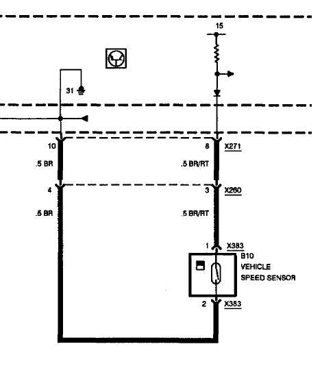
I needed the speedo to work.
Research revealed some not so solid data about pulses per mile, etc...
With all the data I gathered, it just boiled down to this:
Mazda PPM (Pulse per mile): 8000
Mazda PPKM (Pulse per kilometer): (8000/1609.344) x 1000 = 4970.97
4970.97 was my magic number.
The BMW diff has a VSS sensor. It is bolted to the cover, and "reads" a 9 blade wheel integrated in the passenger side axle shaft output.
I also found the proper wiring diagram for the BMW VSS..
Further calculations led me to this:
Tires: 215/40R16
Diameter: 1817.1 mm
Number of wheel revolutions per Kilometer: 550.32
BMW VSS trigger wheel has 9 blades.
BMW VSS pulses per kilometer: 550.32 x 9 = 4952.88
Mazda PPM (Pulse per mile): 8000*
Mazda PPKM (Pulse per kilometer): (8000/1609.344) x 1000 = 4970.97*
* These are the signal values entering the Miata gauge cluster.
These BMW and Miata numbers are actually very close.
(4952.88 / 4970.97) x 100 = 99.636
The difference is merely 0.363%, or I am way off...
I was under the impression BMW was using a hall effect setup. Further inspection revealed things were much simpler...
It was just a friggin reed switch!
All I had to do at this point (since the numbers were so close) was to cobble together a pull up circuit.
Meaning, I just had to us a measly 10k resistor!!!!!!!
And I did just that:
Since I had all the data on rpm vs gear vs speed, I could test my theory..
It is almost bang on.
The speedo indicates ever so slightly too fast, not unlike the stock one behaves.

 12-24-2023, 08:15 PM


 1
1