the thread where Savington asks a lot of really, really dumb questions.
 03-06-2010, 10:56 PM
#81
Elite Member

Join Date: Jul 2005
Posts: 6,420
Total Cats: 84
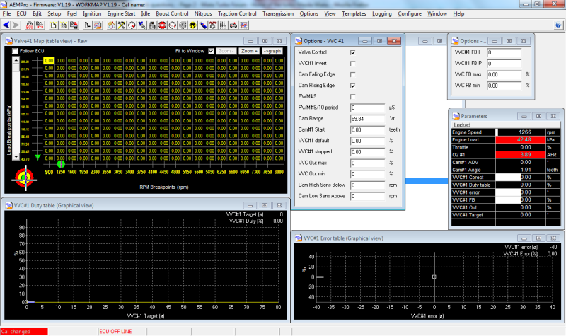
What I don't understand is why the parameter "Cam #1 ADV" is reading 0.
Try setting the option "Cam #1 Start" to 1.7 teeth, just to see if it will start reading something.
You may want to browse the K20 section on the AEM forums.

Reply
 0
0

0
03-06-2010, 11:16 PM
#82
Former Vendor

Thread Starter
iTrader: (31)

Join Date: Nov 2006
Location: Sunnyvale, CA
Posts: 15,442
Total Cats: 2,099
Thanks Rafa. It was really wreaking havoc with my idle. Getting these 1000cc injectors to idle steady at anything except 11.5:1 AFR is a little tough.
Back of the head, temp sensor is just past it. It would be in front of it but there's something funkly in the casting of my head and my temp sensor won't thread into the stock hole (it's plugged on 01 heads normally but its still there). Eventually I will get rid of it entirely and pull my coolant temp readings from the AEM via an IQ3.
Back of the head, temp sensor is just past it. It would be in front of it but there's something funkly in the casting of my head and my temp sensor won't thread into the stock hole (it's plugged on 01 heads normally but its still there). Eventually I will get rid of it entirely and pull my coolant temp readings from the AEM via an IQ3.
Reply
0
0
 03-07-2010, 01:23 AM
#84
Former Vendor
Thread Starter
iTrader: (31)
Join Date: Nov 2006
Location: Sunnyvale, CA
Posts: 15,442
Total Cats: 2,099
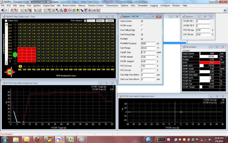
I have a reading. 0.31 cam#1 ADV. It took plugging in the solenoid to make it work. It seems you can't just trigger it with a +12v and get it to read. I'm going to see if I can advance/retard it at idle using the duty cycle table, leaving the target and error tables alone.
Reply
0
0
 03-07-2010, 02:02 AM
#86
Elite Member
Join Date: Jul 2005
Posts: 6,420
Total Cats: 84
When all else fails check the manual.
Page 166 of AEMPro User Guide V2.0.pdf in C:\Program Files\AEM\AEMPro\Instructions describes VVC.
I was right about range. The exact minimum value of the 1.6 number that you typed, minus a small tolerance, should be the "start" value. This will be the position that the EMS will call "zero".
Range has a funky 0.8 factor:
Cam Range = (360 Degrees/# of Fuel Teeth per rev)/0.8
And it doesn't accept the actual range of the cam - I guess the software doesn't really care how far the cam can go, it just uses this number as a scaling factor. Again because it doesn't accept the 112.5 number which the formula would yield, enter half of that, or 56.25, and all your degree units will be in cam degrees.
It does appear too that a bigger number is more *retard*, so think of full advance at 0*, and full retard as 23*.
Because the numbers represent retard and not advance, you need the error table to increase as error increases, and you need the 'I' factor to also be positive. I would first try something like 10% at 5* error, -10% at -5* error, 20% at 10% error, and flat outside that.
As discussed earlier keep the entire duty table flat at the duty cycle that holds the current phase. Except that at max retard, bring it down to zero. So flat all the way to 25*, then zero from 30* onwards.
BTW do this: Configure-Unit-AFR Units, select AFR Gasoline so your AFR reads normally.
Did you install the SB520 diode?
Your VVC out max should be what I posted in the other thread, the max duty needed to get maximum rate of advance.
I would set 'I' to 1, and set VVC FB max and min to +10 and -10 respectively.
Last edited by JasonC SBB; 03-07-2010 at 02:35 AM.
Reply
0
0
03-07-2010, 03:06 AM
#88
Former Vendor
Thread Starter
iTrader: (31)
Join Date: Nov 2006
Location: Sunnyvale, CA
Posts: 15,442
Total Cats: 2,099
Will do, next week. My number 2 injector locked wide open while I was fiddling with all of this. Sending them all back along with a very nasty phone call on Monday - these are about 40 miles old.
Reply
0
0
03-08-2010, 03:08 AM
#89
Former Vendor
Thread Starter
iTrader: (31)
Join Date: Nov 2006
Location: Sunnyvale, CA
Posts: 15,442
Total Cats: 2,099
OK, folks, I need a bit of help with this. I switched injectors this evening to isolate the issue and it appears the AEM is locking injector number 2 open as soon as I crank the car. We're talking enough fuel to hydrolock the cylinder, and it blows puddles out the exhaust. I'm reloading my calibration to see if I somehow managed to screw something up there, but what's my next recourse? Send the box back to AEM?
Reply
0
0
03-08-2010, 05:04 AM
#90
Former Vendor
Thread Starter
iTrader: (31)
Join Date: Nov 2006
Location: Sunnyvale, CA
Posts: 15,442
Total Cats: 2,099
It appears to be fixed. Reloaded my calibration from the dyno a few weeks back and it appears to have stopped. Going to give it 12 hours to clear the fuel from the exhaust and try to start it back up.
Jason, do you know what the period of the solenoid is (the first box)? I can scope my friend's 2001 tomorrow but wondering if you've already done it.
Jason, do you know what the period of the solenoid is (the first box)? I can scope my friend's 2001 tomorrow but wondering if you've already done it.
Reply
0
0
03-08-2010, 11:40 AM
#91
Elite Member
iTrader: (9)
Join Date: Jun 2006
Location: Chesterfield, NJ
Posts: 6,893
Total Cats: 399
OK, folks, I need a bit of help with this. I switched injectors this evening to isolate the issue and it appears the AEM is locking injector number 2 open as soon as I crank the car. We're talking enough fuel to hydrolock the cylinder, and it blows puddles out the exhaust. I'm reloading my calibration to see if I somehow managed to screw something up there, but what's my next recourse? Send the box back to AEM?
But glad to hear it's fixed.
Reply
0
0
03-08-2010, 10:33 PM
#93
Former Vendor
Thread Starter
iTrader: (31)
Join Date: Nov 2006
Location: Sunnyvale, CA
Posts: 15,442
Total Cats: 2,099
Guys, we have a problem. Something in the VVT system is locking the 2nd injector (the one that fires on 0 tooth) open as soon as the motor cranks over. I just switched the #2 injector to INJ10 because I thought it was damaged. Fired up fine. Went to plug VVT in and immediately had the same problem. I am wondering whether something in the injector phasing is screwing things up.
I am going to turn off PWM#9 and the VVT control in the software once the car cools down and I can empty out the cylinder yet again - if the car runs normally with VVT control turned off we need to solve this before further testing can continue :(
I am going to turn off PWM#9 and the VVT control in the software once the car cools down and I can empty out the cylinder yet again - if the car runs normally with VVT control turned off we need to solve this before further testing can continue :(
Reply
0
0
03-08-2010, 11:34 PM
#95
Former Vendor
Thread Starter
iTrader: (31)
Join Date: Nov 2006
Location: Sunnyvale, CA
Posts: 15,442
Total Cats: 2,099
Jason, pretty sure you have to enable each one in VVC#1/2 options to control solenoids vs. injectors. I had the exact same issue with injector driver 2, thought I had blown it out inside the box so I switched.
Also, there's no fuse in the VVT slot, so the VVT solenoid was never getting +12v power. Durr. Once the car is clear of fumes in an hour or so, I'll go back out and try again with the VVT solenoid unplugged. It ran fine, and then as soon as we plugged the VVT solenoid in, it immediately flooded.
I do not know whether the flooding is isolated to software settings or having the solenoid plugged in - I will check that in a bit.
Reply
0
0
03-09-2010, 01:16 AM
#98
Elite Member
Join Date: Jul 2005
Posts: 6,420
Total Cats: 84
No the phasing just changes when the injector fires.
Just a random check, try inj output #6.
The only other thing I can think of is that there is a short in your harness between the wire going to the injector and the VVT solenoid.
Just a random check, try inj output #6.
The only other thing I can think of is that there is a short in your harness between the wire going to the injector and the VVT solenoid.
Reply
0
0
03-09-2010, 02:21 AM
#99
Senior Member

Join Date: Dec 2007
Posts: 741
Total Cats: 20
Looks like hardware issue to me, not software ...
After Savington mentioned flooding cylinder #2 I did some digging in the software and seems to me to make the '90-'92 Miatas work (the 1710 box covers all the '90-'95 Miatas), on the daughter board AEM have connected the injector output 9 & 10 to injector output 1 & 2. This way they could implement the batch injection (software and the ECU doing sequential and the daughterboard faking the batch by shortening the driver pairs). Just take a look at the '90-'92 Miata calibration ... 9 & 10 injectors are enabled ...
Are you guys sure, outputs 9 and 10 are really on the extra connector 3O and 3P at all?
I remember AEM Engineer telling me in the past about the 1710 Miata box needing hardware tweaking to support VVT (because there are no injector outputs 9 and 10 routed to the connector) and I mentioned it here some months ago . But someone argued about my statement saying 3O and 3P are injector 9 and 10 (I have no idea whether he made any tests at all).
So ... my suggestion is test the injector outputs manually to see if you have 9 and 10 in the connector at all or whether those two are connected to pins for 1 and 2 and you either have to move some jumpers on the daughter board to separate them or you may even have to cut some traces on the daughter circuit board and route them to the proper pins.
To do a test:
1. Open AEMPro, go to Options -> Injector screen
and turn off all injector outputs there (so the software temporary doesn't treat them as injectors).
2. Disconnect the plugs from the injectors.
3. Since all our injector outputs are not treated as injectors anymore but as general LS drivers.
In AEMPro, open Options -> Configure Outputs and there manually toggle Fuel 1, 2, 9 and 10 to ON one by one.
Monitor their status in a parameter window (Ctrl-P) and check with a multimeter the pins 2U, 2V, 3O and 3P.
My prediction is that when Fuel 9 is ON, pin 2U will be grounded instead of 3O and when Fuel 10 is ON, pin 2V will be grounded instead of 3P.
So, to make 9 go to 3O and 10 to 3P, you'll either have to move some jumper or do some trace cutting and/or soldering on the daughter board
This is just for Savington's AEM EMS. Jason uses one with a Honda daughterboard so I guess his is fine.
Reply
0
0


