When you click on links to various merchants on this site and make a purchase, this can result in this site earning a commission. Affiliate programs and affiliations include, but are not limited to, the eBay Partner Network.
I'm not denying it would have fixed the problem without warping the throttle plate AND would have also locked the screws in place. But I'm unsure of the tape's ability to resist the massive velocity of passing air given my 50% success ratio with duct tape (and most other tools). And though I have managed to send throttle body screws through an engine, and then complete another race on that same engine- I don't expect to be that fortunate if the tape releases and enters a runner, or further. I suspect it's sticky enough to glue my piston to the cylinder head and bend a valve, or worse snap a rod. That said, I respect the widely accepted use of duct tape in both automotive and aeronautical applications. I just don't have confidence in my ability to use at such an advanced level.
Whats the bolt pattern on those ford units? I need something for the MZR, the subaru throttle body I have will work with a spacer and some ovaled out holes but its got a really long shaft.
Got the new eBay throttle body. The screws are hollow tipped and crimped to keep them from backing out. Measuring showed the plate to be same size as my older model Ford throttle body with idle valve attached. So I put a point punch and some light tapping to the ends of the hollow screws and rounded them. They backed right out with a philips head screwdriver. Flat plate swapped right in to my current TB without any clearance issues. Start the car up and the TB dropped my idle to 300rpm.
I developed an oil leak at the front of the engine that I thought was a main seal. Went through and checked the torque on the oil pan bolts. Two were not very tight- one on the exhaust side, and another on the intake side but screwing into the oil pump. When I tried to tighten the oil pump bolt it never got any tighter, just spun snugly. Tried another bolt and the same thing. Fortunately the bolt comes through the oil pump flange and now has a nut on top to seal the pan. Lucky me.
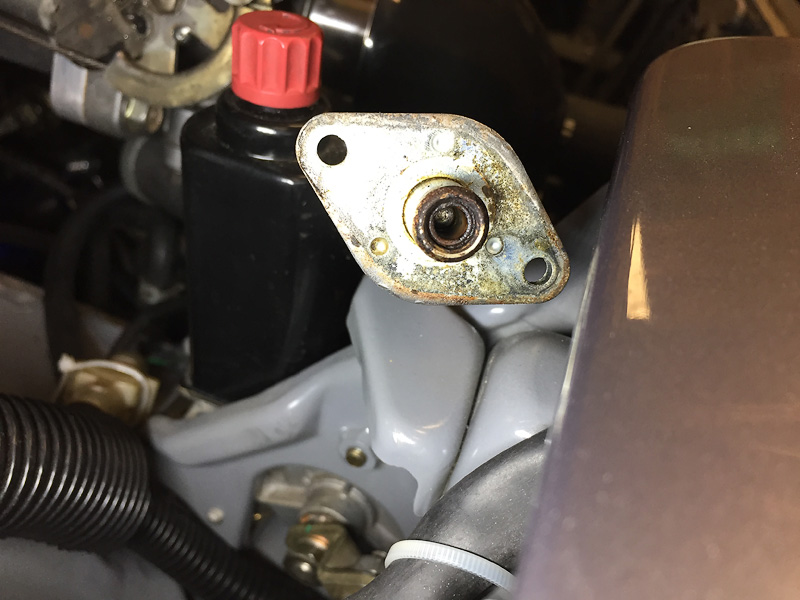
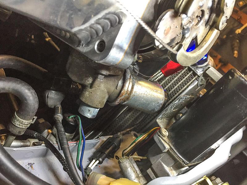
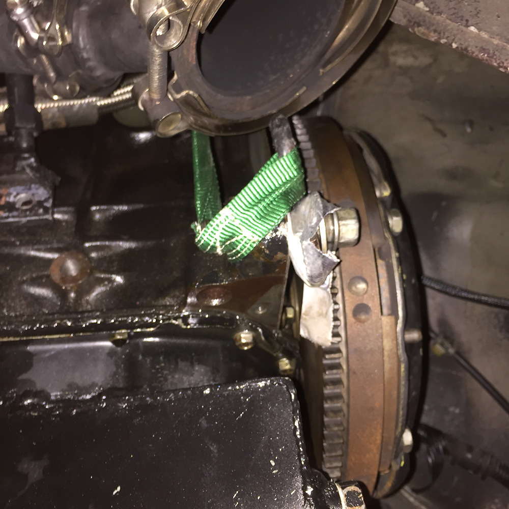
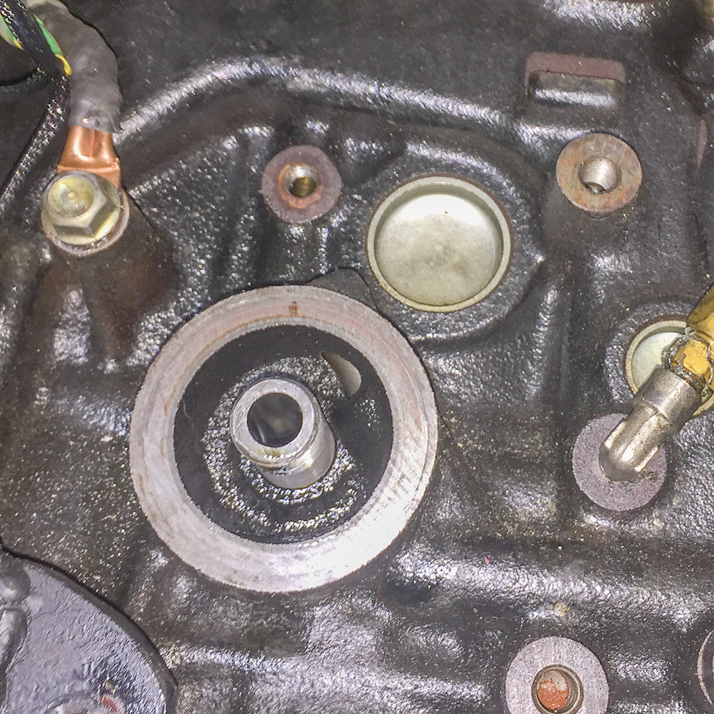
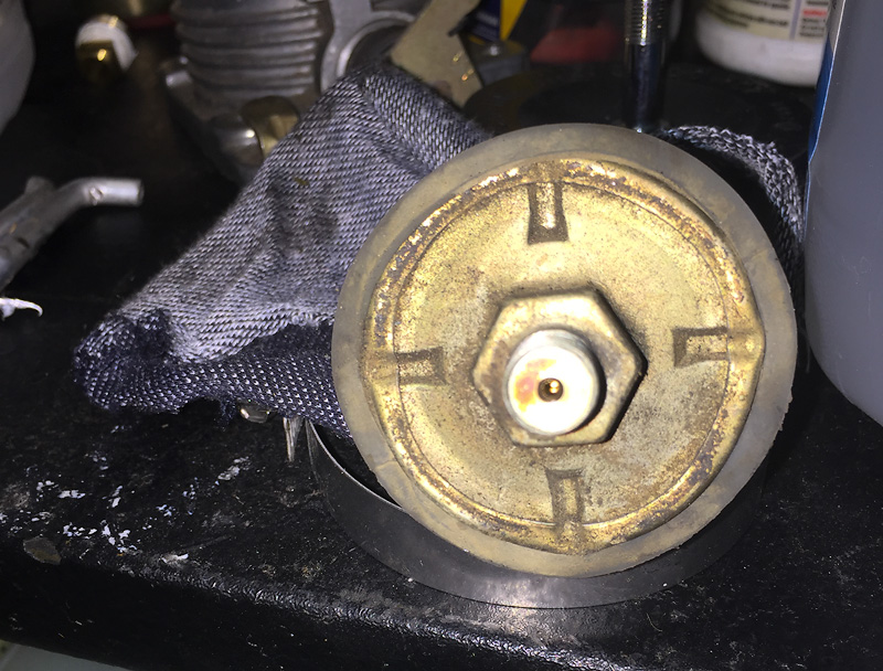
The other issue I've been dealing with is a serious delay in startup oil pressure. I'm using the same sender that's been in the FE3- and the same gauge that was on the car- both working prior. I've doubled checked the oil cooler setup, including sandwich plate, the oil filter and moved on to the sender. I've been using the large hex end on the housing to install/remove the sender with delicate hands and it's worked so far. But this time I couldn't get it to back out- instead the housing pinches that anchor it to the base opened up and the housing started to rotate.
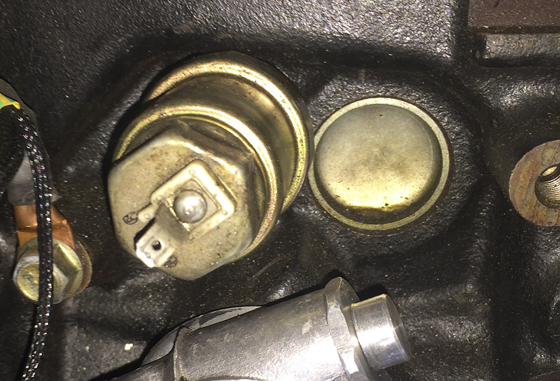
Of course I made a few rotations on the housing before I suspected something was up. Tried to get to the 17mm hex on the cast base, but it's on a boss that's in a recessed area of the FE block. I can get a crows-foot on it, but can't rotate it enough to reorient the crows-foot to repeat.
I think my only option to replace it (without pulling the engine) is to destroy it so I can get to the cast base and back it out. Before making that move, I decided to plug it back in and try it one more time. This is the result after sitting for 45-60 minutes:
Built a lambda and timing table and went for a drive on a rough VE table. Now have a log and retuned VE. Need to do more driving.
I have a horrendous vibration/noise in high vacuum from the drive line. Looks like I made my oil pan sump a little too long and it's contacting the bell housing/gasket. I'll have to drop the pan to fix that - so I'll change the oil sender then.
Rather than addressing an oil pan leak, excessive throwout bearing noise, a whacked out oil pressure sender and some PPF adjustments, I decided to do some driving and tuning. I feel better now. I've been driving and tuning on straight wastegate at 150kpa/7psi. Spool sucks and it does not appear to be leaks pre-wastegate/turbo. I can't see any evidence of it and the IAT doesn't indicate any excessive turbo duty. At this point I'll either disconnect the signal hose to see if the wastegate is cracking and leaking early OR hook up the EBC and see if the spool changes.
Tuned my idle after replacing the bad idle valve that came on my Ford TB. Turns out the TB/idle valve flanges are the same across years/models of Fords, so I just pulled a spare and adopted the connector.
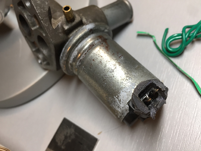
bad solenoid:
Have also been working on throttle tip-in.
Got to use my Eastwood racheting bit driver for something other than the Benz's blind AFM potentiometer philips head screws.
Swapped out the top oil cooler line fitting from a cast 90� to a tube 45�. Didn't really notice any oil pressure changes, though it's claimed to be a 5psi improvement. Maybe at high rpm?
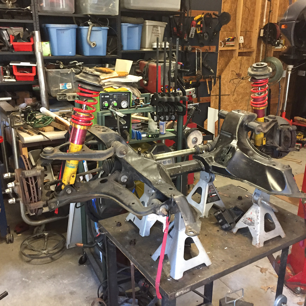
Installed some QA1 7HT-250 (7" High Travel 250#) springs on the rear.
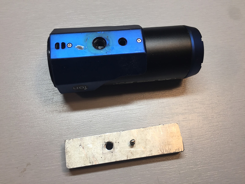
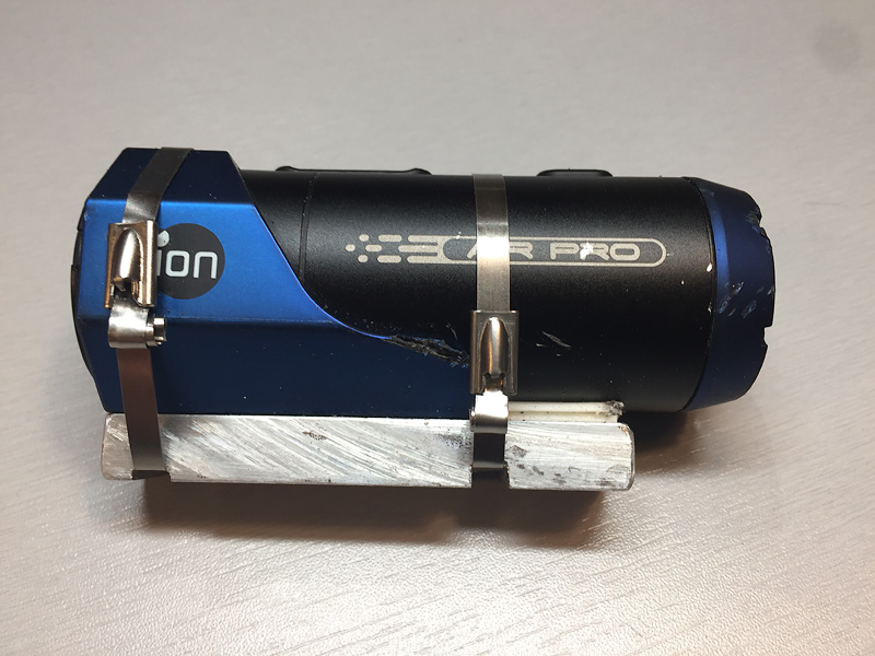
"Fixed" the stripped plastic mount threads on my cheap Ion Air action cam. Stainless steel zip ties FTW.
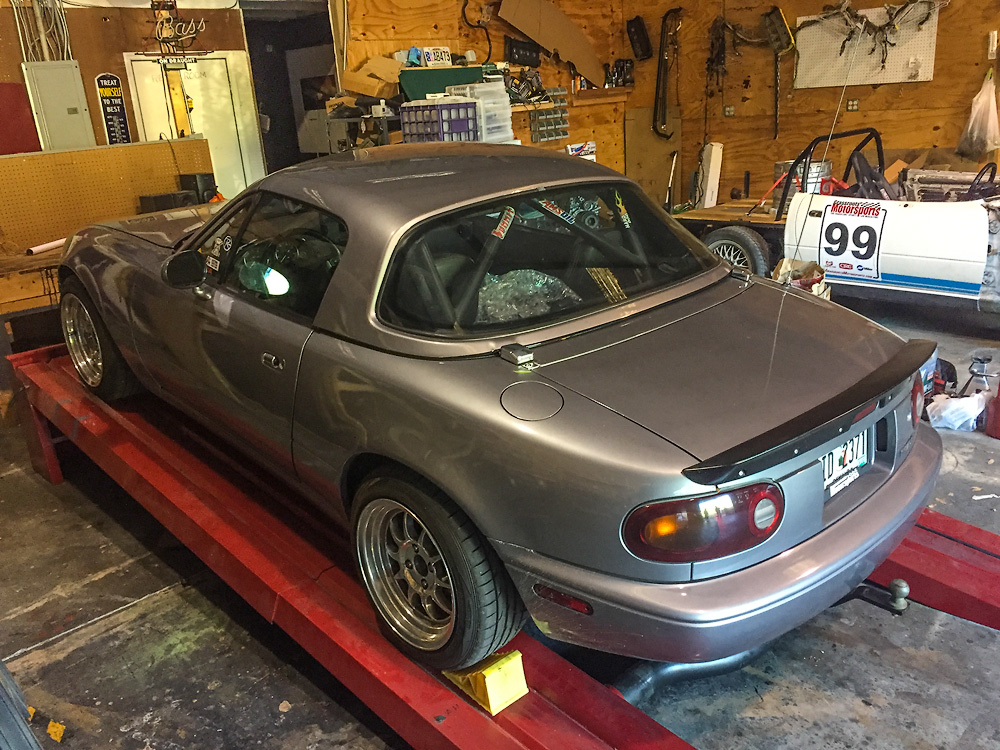
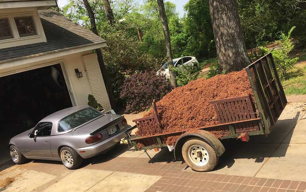
I drove the car about 150 miles and compiled a list of things to do before I embarked on a Florida road trip. Somehow I managed to get it all done and drive the car enough to instill the confidence needed for the trip. The work to be done required engine access at the bottom. I opted to drop the subframe rather than break all my fluid connections and risk future leaks since I didn't have a lot of time to test drive before the trip. Not to mention all the added electrical and intake connections. Of course the lift is what makes the plausible.
This was also a good exercise in learning what items should just be removed in the process rather than attempting to work around them. That includes dropping the steering rack and pulling the AC compressor from the block (no line break, just moving/hanging with hoses connected).
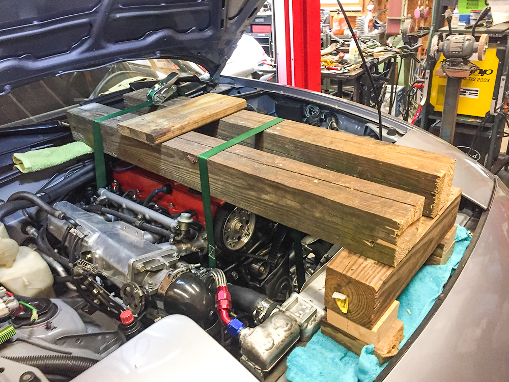
I started off with some lumber and built up a rig to hang the engine.
I unbolted the calipers and hung them from the body, unbolted the shock top hats and steering rack/column. I lowered the car down to rest on jack stands atop a rolling bench and removed the subframe mounting hardware. Then slowly raised the car and the subframe stayed behind. It was that simple. I've done the rear subframe a couple of times on the Miata and once on my Benz, so I had a good idea of the process.
Simple? Yes. Perfect. No. Meant to check this, forgot and found that I'd torqued my strap down with a mess at the trans bolt. It was tight, but put enough fear in me to fix it. Though the engine can't fall out of the car, it would likely move enough damage hoses or wires.
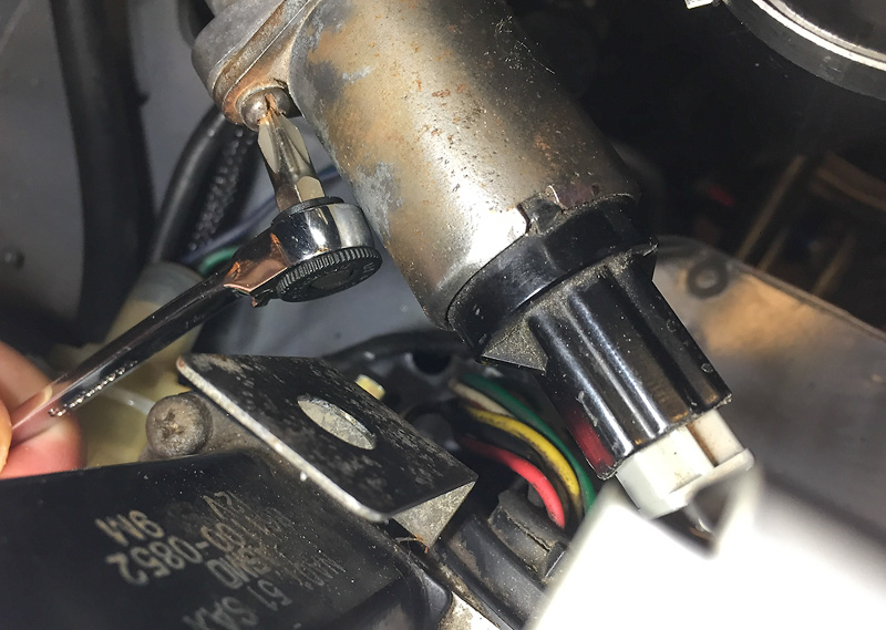
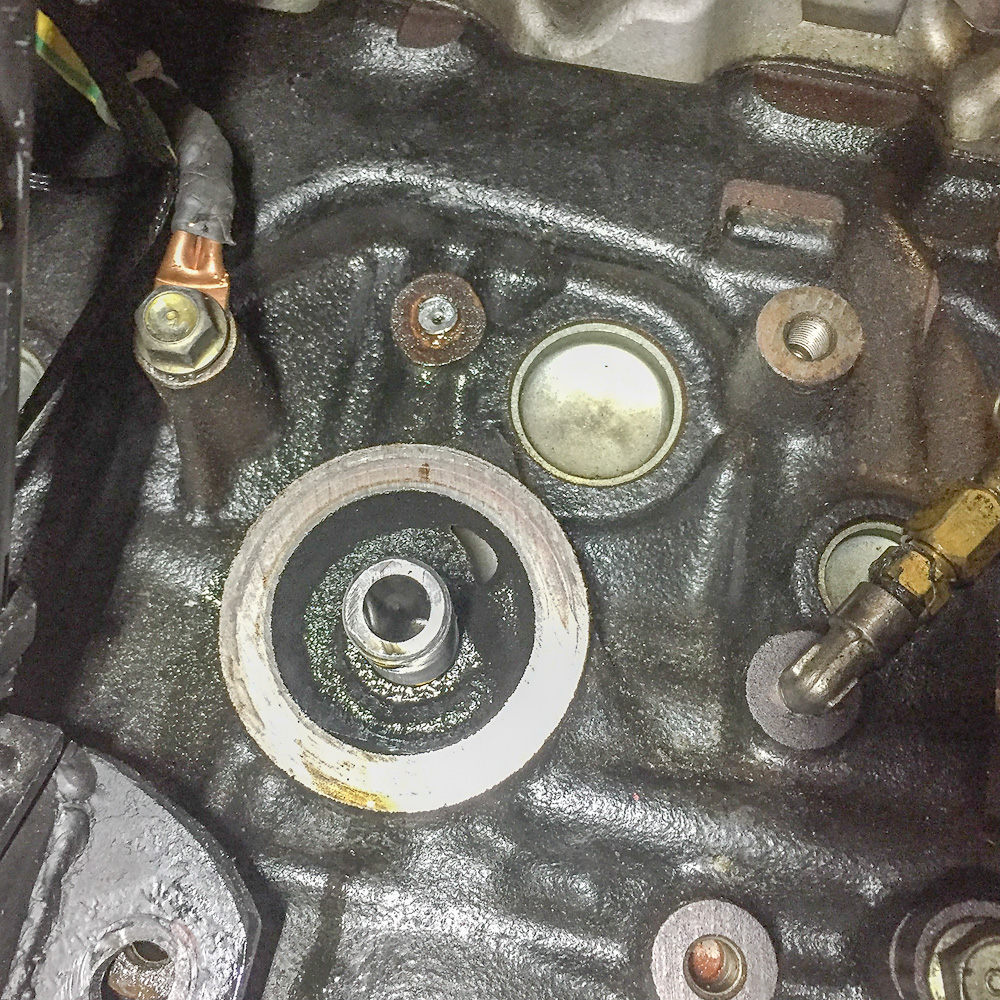
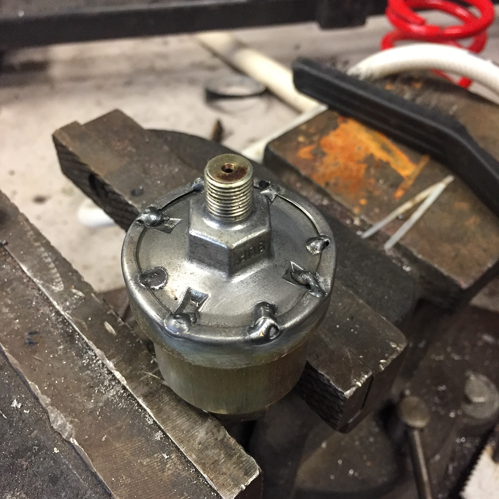
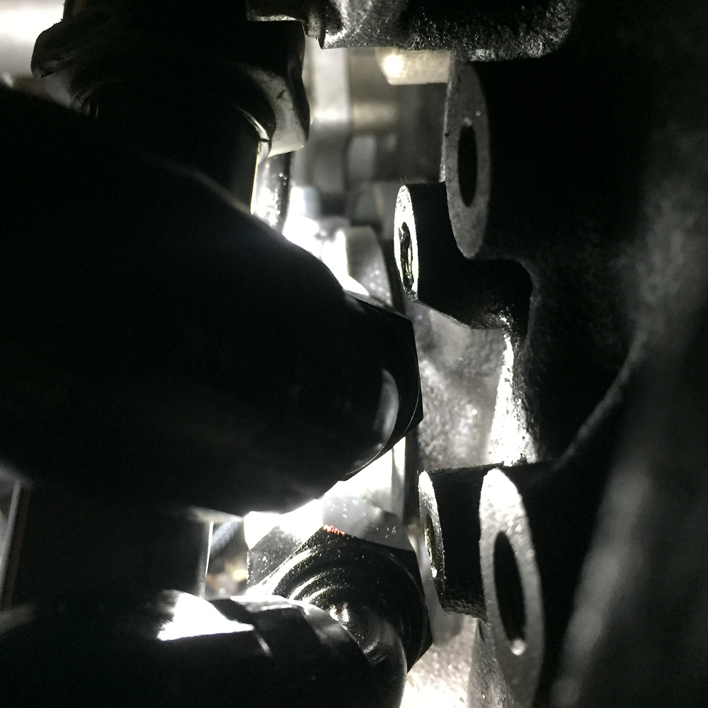
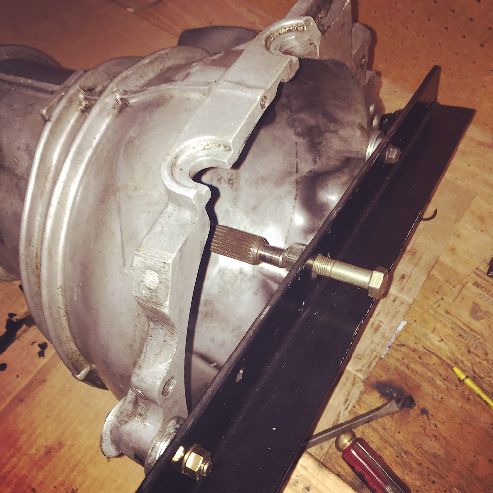
I needed to pull a flakey oil pressure sender, but it is buried deep on the side of the FE block and you can't put a wrench on the cast base hex. The only option is to use the large hex on the case/shell but that was spinning on the base.
Only option was brute force. As expected that left me with a stub to remove from the boss.
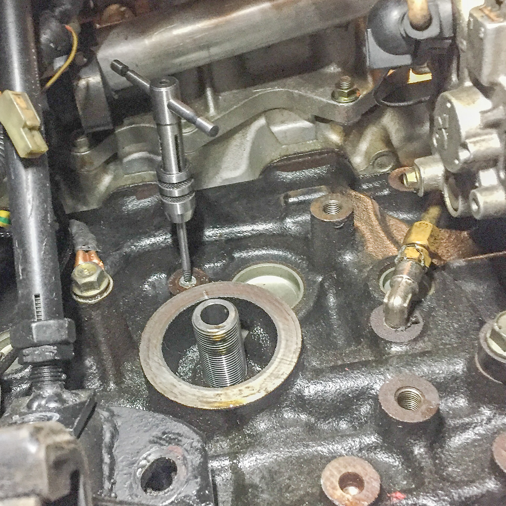
Some light taps to an easy-out in the center and it backed right out.
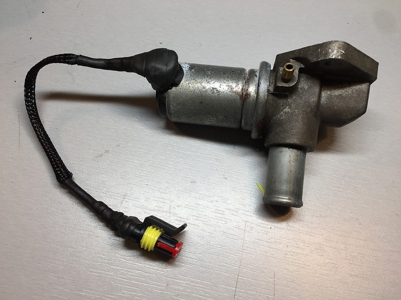
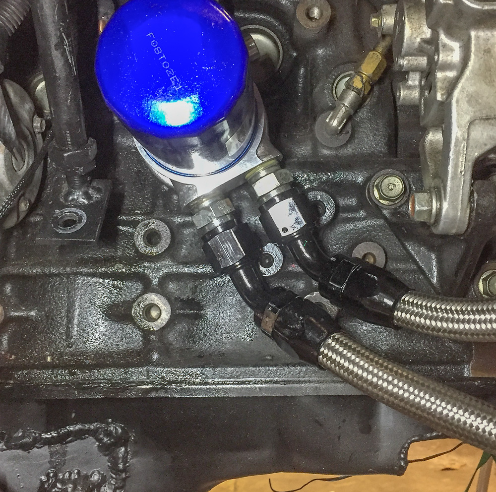
I tack welded the case/shell to the base on the "new" sender to assure it would not spin when installed/removed.
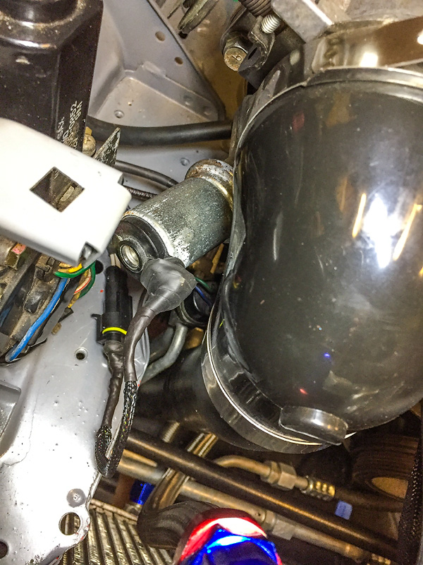
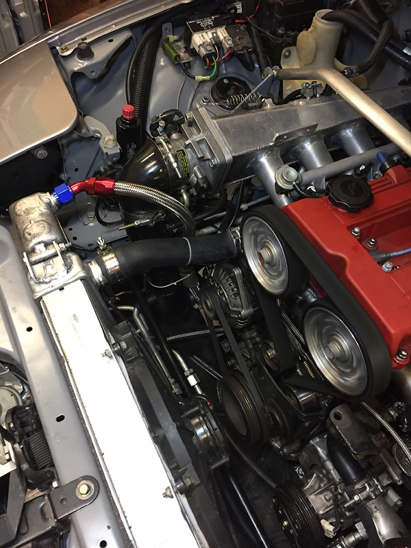
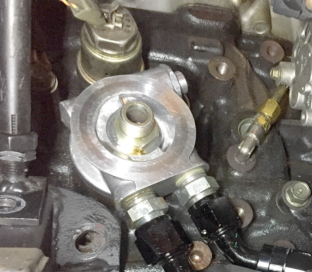
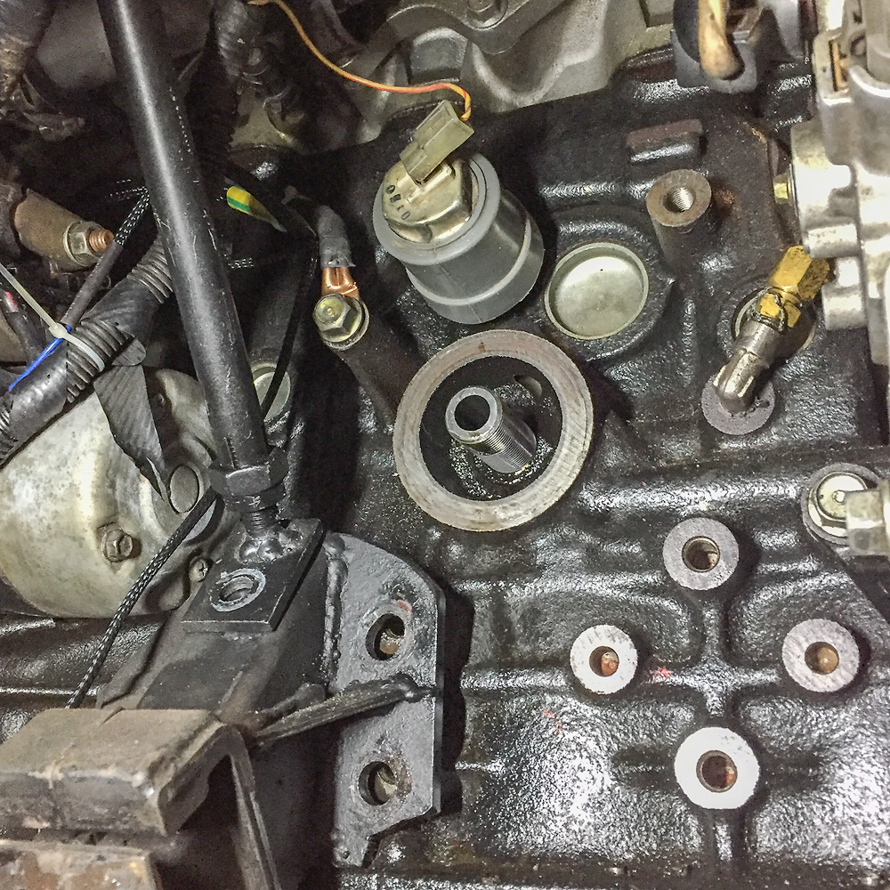
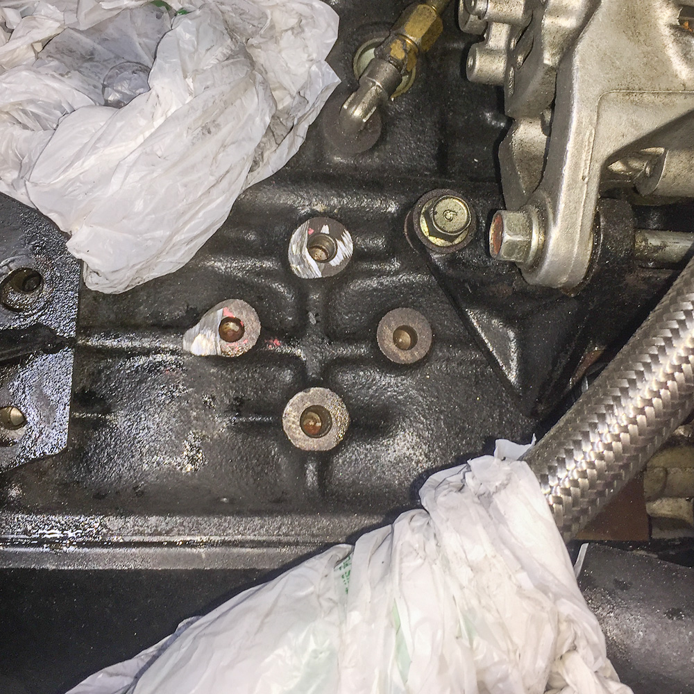
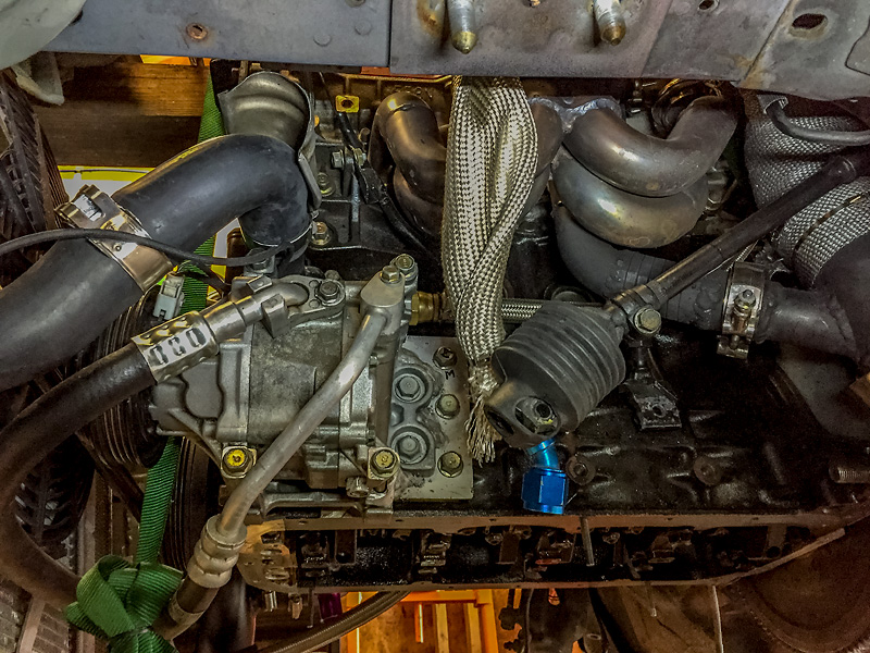
New sender installed- now on to tightening and adjusting the weeping oil cooler lines. Once I had the fittings tightened and aimed for a neutral load on the hoses, they were interfering with two of the four bosses to the lower right of the oil filter boss.
Bosses ground for clearance.
Sandwich plate, lines and filter installed.
Other to-do items included adding another shim to my oil pump to raise the peak pressure and removing �" from the drain corner of the oil pan sump to get it above the bottom of the subframe. I also found what I believe was the cause of my delayed oil pressure rise on start up. I found a small pinhole in one of pickup tube welds AND I used RTV to seal the pickup tube to the pump. I know better than using RTV and had three new gaskets for the job, but failed anyway.
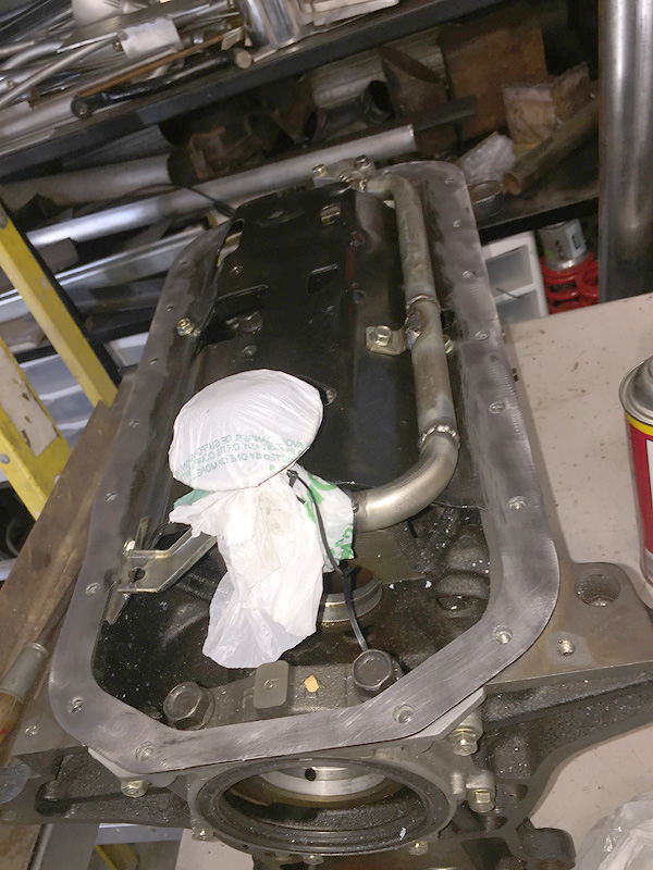
I use a spare block for mocking/fabbing the pan. Here I'm checking for pickup depth at the sump.
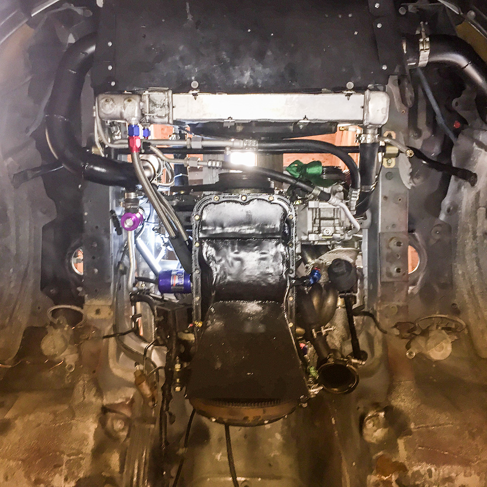
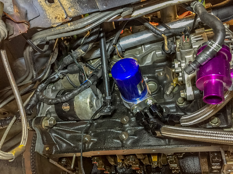
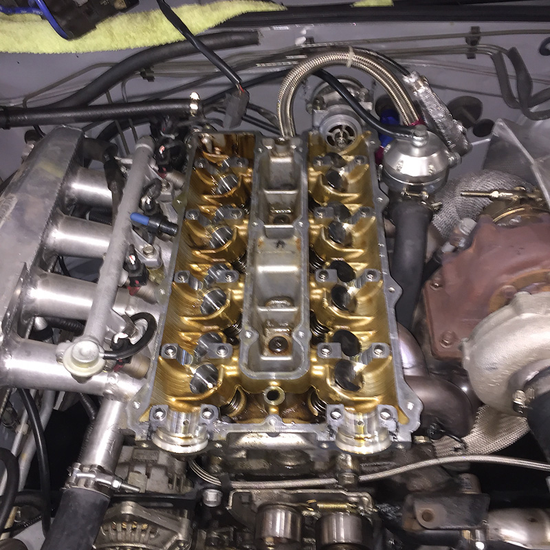
I took some reference shots of the engine while I could so I have something to look at in the future if I'm work on the sides and can't see.
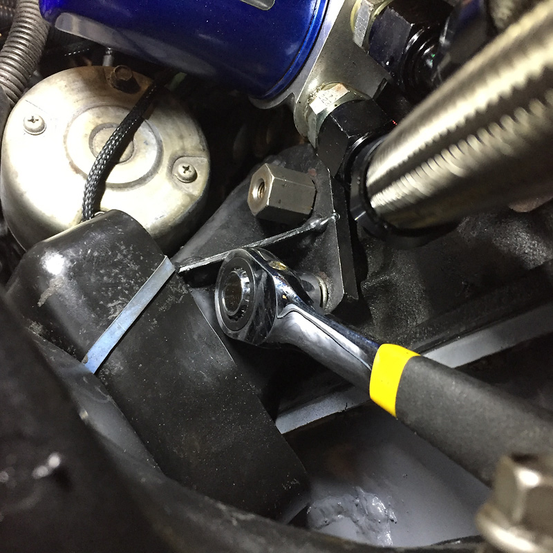
Fortunately I have THE wrench needed for that one motor mount bolt.
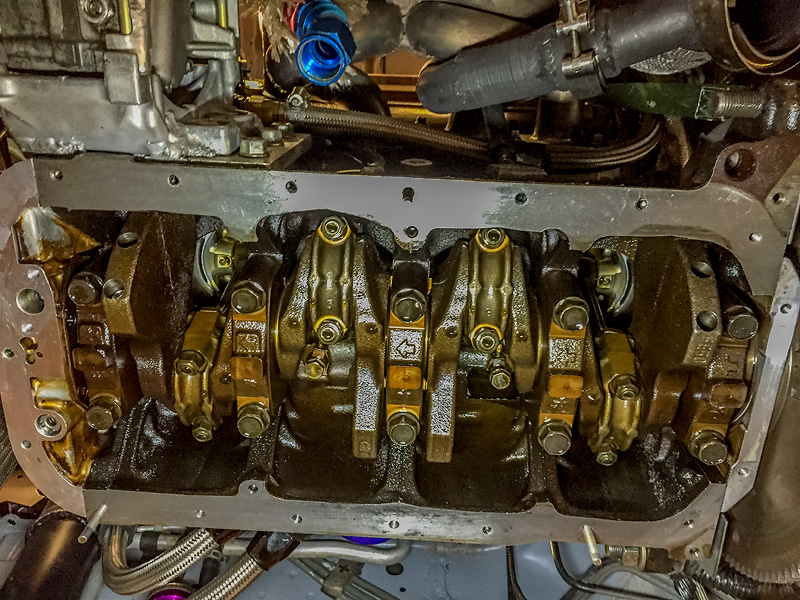
Swapped out some dead HLAs with others from spare heads. They all need to be cleaned though.
There are those who get it and those who don't. Right? Though I think we were in the minority.
Speaking of work- I took the car on a 900+ mile road trip and the work paid off. The only issue I had was a transmission failure half way through the trip because of glass5spd. I stated somewhere I was getting around 2500 miles from the 5spd and that confirms it. Picked up another one in Tampa and got it installed the day before Miatapalooza.
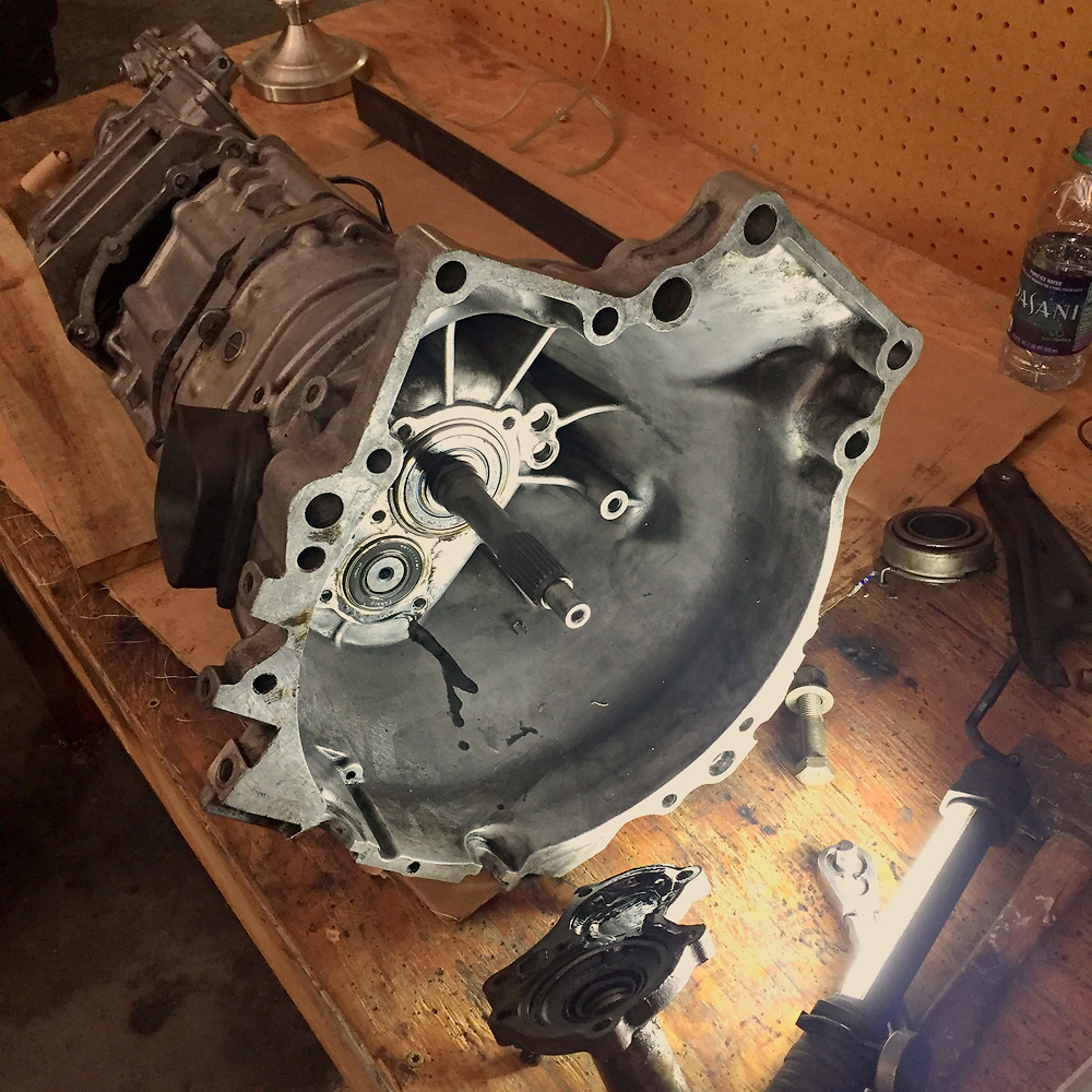
I forgot what a pain it is to do this transmission. Because the Miata trans is a bunch of cases bolted together, it's more than "just a bellhousing swap". When you pull the bolts you get four pieces- which means you have to clean and rtv all of them to put it back together. All this has spurred a renewed interest in building a robust transmission using an FD RX7 gearbox and true Mazda Bongo (full size Mazda van) bell housing. This will be a bolt-in solution since the Bongo used an R (Mazda big) transmission without a twist as the FD does. I will only need to fab an adapter for the ppf and get a drive shaft made with an R yoke and small pinion flange. I think half the problem with 5spds is that they're all old- the odds are good you'll get a worn transmission buying used in addition to the beating it will get with added power. This last trans to let go was an NB 5spd.
My Instagram masterpiece shot at Ochlochonee River State Park- one of the stops on the way to Tampa.
Fortunately my buddy's shop as a quick lift type ramp. Old school but nice height and works well with creepers.
Step one- make a case splitter/puller to get this thing apart. Fortunately my trans uses one "through bolt" to mount by the starter - which see is an integral part of my SST.
Case is split making four pieces to seal (and the front bearing/shaft cover).
Once the new gear box is in place you have to drive the case front section down over the bearings - which requires balancing the assembly on the tail, a 2x4 and big hammer. At that point you have get the main bearing down low enough get the C clip wedged in its slot. It's a time eater for sure.
Well picking up an FD transmission from the salvage yard just requires a long lunch (they're down the street). But if it's not on the garage floor, it will never happen.
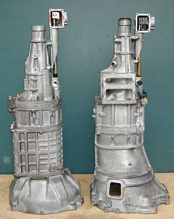
Size comparison:
The R trans doesn't occupy much more space than the small one. Here's an Rx-7 Turbo II R transmission on the left and a Miata transmission on the right.
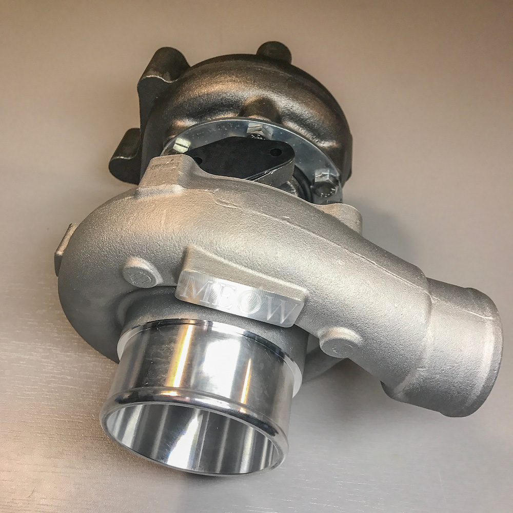
Turns out I've been running with a mismatched turbine housing and wheel. The original eBay turbine wheel has a different contour on the inducer/major than a Garrett- it's larger/wider. The Garrett turbine housing I used was cut to fit this eBay wheel. When that turbo died shortly after install (my bad) I bought a standard Garrett t3/t4 without a turbine housing so I could just "drop it in" to my setup without having to fab anything. I ran it like that forever. It didn't become obvious to me that there was something wrong until I stepped up to an eBay/china .63AR housing (story here) and spool suffered dramatically due to the large gap between the inducer/major blade and housing.
I should only need to get a genuine Garrett T3 turbine housing at this point to install my old turbo and attain the expected spool. But I thought I'd try out a smaller eBay turbo first- hard not to when they're $110 delivered. I bought what was advertised with specs that made it out to be a medium sized t3/t4 but it turned out to have the same specs as the turbo MKturbo uses- similar to a Garrett 50 trim compressor, 50AR and stage I 48AR turbine. Regardless I'm going to try it out. When I get sick of it, I'll either bring over my 50 trim T4 compressor wheel/housing (17.5% compressor/turbine differential) or just get the Garrett t3 stage III housing.
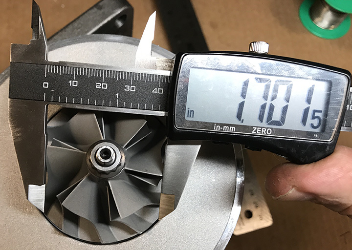
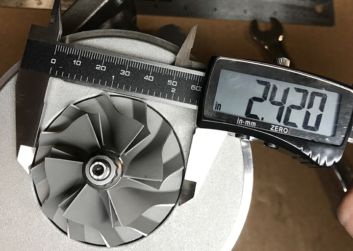
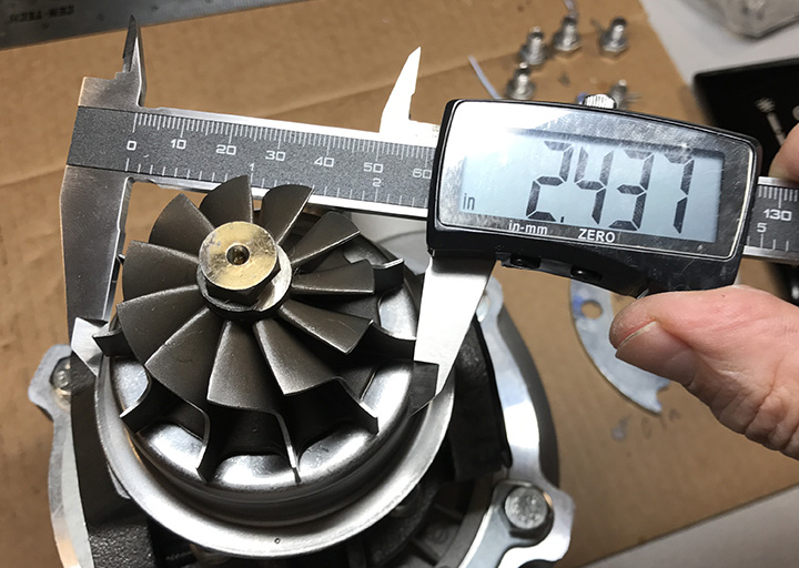
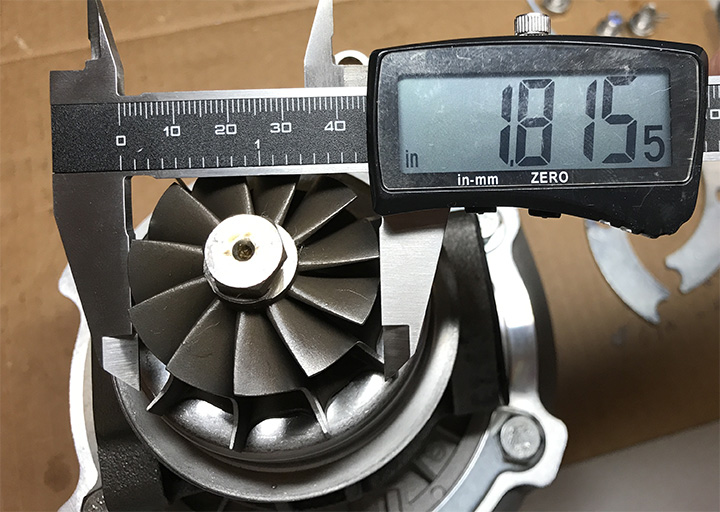
I collected specs from the eBay ads for t3 based turbos and came to the conclusion that there are three different sets of specs used: Small T3 similar to a 50 trim, a medium T3/T4 (listed with a stage I turbine wheel/housing) and large T3/T4 (stage III wheel/housing). I bought the medium T3/T4 pictured above which uses the model number TBCT04EE48. What I received based on measurements is the small T3 similar to a 50 trim T3 (and the MKTurbo piece). Of note- the eBay wheels can differ from the Garrett (and other brands) in contour and height.


 07-07-2016, 10:33 AM


 1
1


 I've been driving and tuning on straight wastegate at 150kpa/7psi. Spool sucks and it does not appear to be leaks pre-wastegate/turbo. I can't see any evidence of it and the IAT doesn't indicate any excessive turbo duty. At this point I'll either disconnect the signal hose to see if the wastegate is cracking and leaking early OR hook up the EBC and see if the spool changes.