Build Thread (FE3, RX7 TII, EFR 6258, MS3)


 06-20-2011, 11:42 PM
#24

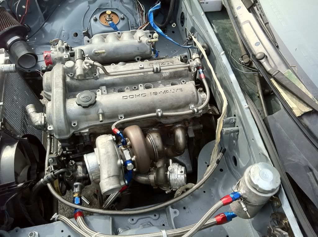
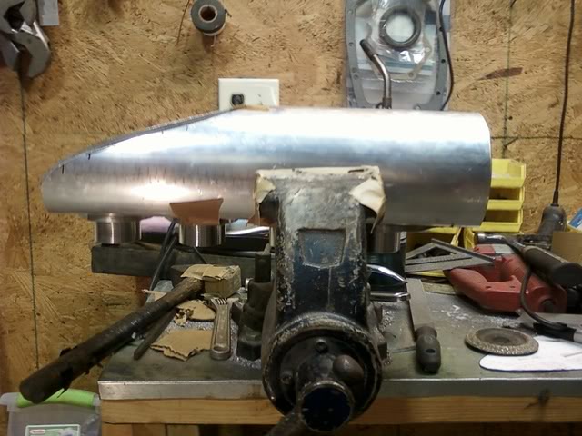
A little update. I ended up droping the engine and trans in the car last weekend and made some motor mounts. I lined up the shifter perfect in the stock location and had about 4 inches between the firewall and the back of the block! Plenty of room for a coolant reroute but probably not so good for weight ratio. as usual the oil pan will be one of the shortest ever made (planing on finishing it when i pull the motor back out.) and theirs just enough clearance for the timing belt to fit in between the hood and gear. (ill remove the structural support for the hood for more clearance.) I got started on the intake manifold tonight and ill probably be working on it for the next few days after work.
In the meantime if you have any suggestions on top mount exhaust manifolds and suggestions on DIY exhaust manifolds please feel free to post up links and images for inspiration! Im planing on using a MIG with 308 wire and 100% argon to weld the butt weld fittings together. I hear alot of people saying TIG is the only way to go but havent seen any real horror stories from people that have done MIG so im down for being a guinea pig.
In the meantime if you have any suggestions on top mount exhaust manifolds and suggestions on DIY exhaust manifolds please feel free to post up links and images for inspiration! Im planing on using a MIG with 308 wire and 100% argon to weld the butt weld fittings together. I hear alot of people saying TIG is the only way to go but havent seen any real horror stories from people that have done MIG so im down for being a guinea pig.

Reply
 0
0

0
06-22-2011, 12:42 PM
#25
Elite Member
iTrader: (8)

Join Date: Dec 2008
Location: Kingston, Ontario
Posts: 2,910
Total Cats: 51
You will be fine with MIG. Just use a large nozzle and a high flow rate to keep gas coverage the best you can.
In terms of design, check my manifold...

Runner #3 comes off the head, down and to the fender side of the collector.... runner #4 comes down and wraps around #3 to the inner rear side of the collector.
Edit: doing it over, i would have spaced the turbo further from the head to get runner #2 more straight. But this will work.
In terms of design, check my manifold...
Runner #3 comes off the head, down and to the fender side of the collector.... runner #4 comes down and wraps around #3 to the inner rear side of the collector.
Edit: doing it over, i would have spaced the turbo further from the head to get runner #2 more straight. But this will work.
Reply
0
0

 06-23-2011, 10:20 AM
#29
Elite Member
iTrader: (8)
Join Date: Dec 2008
Location: Kingston, Ontario
Posts: 2,910
Total Cats: 51
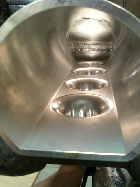
They wont have the chamfers when you are done fitting.
practice with a few peices prior to doing yours and it will be fine. i hope your mig is 210v or you wont have a very high duty cycle at the amps needed to weld it or you will be tripping a breaker.
Tip! Clean your pipes REALLY well prior to welding... the whole pipe. because sanding the finish down to look nice is really tough once its welded. When you MIG this together, try to cover other runners up with a flame resistant blanket to prevent splatter.
Reply
0
0
06-23-2011, 12:10 PM
#30
QUOTE=shlammed; They wont have the chamfers when you are done fitting.True. 
practice with a few peices prior to doing yours and it will be fine. i hope your mig is 210v or you wont have a very high duty cycle at the amps needed to weld it or you will be tripping a breaker. Yep Miller 211 MVP autoset. picked up the spool gun to do my aluminum stuff too.
Tip! Clean your pipes REALLY well prior to welding... the whole pipe. because sanding the finish down to look nice is really tough once its welded. When you MIG this together, try to cover other runners up with a flame resistant blanket to prevent splatter. Good tip. This happened to me last night when i was working on my intake mani. the main plenum was sitting off to the side and cought some splatter
Reply
0
0
06-23-2011, 07:17 PM
#31

Practice A LOT with that aluminum spool gun. They are a pain in the *** to use and make welds that are even half way presentable. I found it easier to just learn how to use the TIG than figure that damn thing out, if that tells you anything.
And any chance of making of those adapter plates for the trans? (I seem to recall the FE3 and BP share a bell-housing pattern). I would much rather do it the way you did and weld the bell housing to the plate than make an adapter.
And any chance of making of those adapter plates for the trans? (I seem to recall the FE3 and BP share a bell-housing pattern). I would much rather do it the way you did and weld the bell housing to the plate than make an adapter.
Reply
0
0
06-23-2011, 08:19 PM
#32
Elite Member
iTrader: (2)

Join Date: Jan 2007
Location: Los Angeles, CA
Posts: 8,682
Total Cats: 130
You will be fine with MIG. Just use a large nozzle and a high flow rate to keep gas coverage the best you can.
In terms of design, check my manifold...
Runner #3 comes off the head, down and to the fender side of the collector.... runner #4 comes down and wraps around #3 to the inner rear side of the collector.
Edit: doing it over, i would have spaced the turbo further from the head to get runner #2 more straight. But this will work.
Shlammed. Manifold. Is. Sick.
How much boost are you running?
Reply
0
0
06-23-2011, 11:07 PM
#33
Practice A LOT with that aluminum spool gun. They are a pain in the *** to use and make welds that are even half way presentable. I found it easier to just learn how to use the TIG than figure that damn thing out, if that tells you anything.
And any chance of making of those adapter plates for the trans? (I seem to recall the FE3 and BP share a bell-housing pattern). I would much rather do it the way you did and weld the bell housing to the plate than make an adapter.
And any chance of making of those adapter plates for the trans? (I seem to recall the FE3 and BP share a bell-housing pattern). I would much rather do it the way you did and weld the bell housing to the plate than make an adapter.
Reply
0
0
06-23-2011, 11:13 PM
#34
Im planing on 10 psi or 300 whp whatever i hit first for now. Ill probably break the engine in on that and then work on getting more traction. I pride myself on being a halfway decent driver but there's going to be a learning curve with a 200 hp jump. From what ive seen on this forum ill probably end up getting sick of 300 at the wheels and go all out eventually 
Reply
0
0
06-23-2011, 11:42 PM
#35
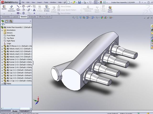
Its not too late to go out the front like most people do but what do you guys think of this?
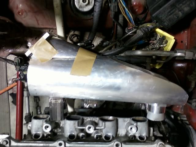
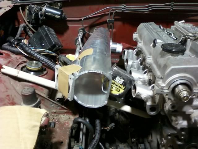
In this case id drill a 3" hole under/behind the passenger headlight and run the piping similar to the hot side setup that M2cupcar is running. I would be able to run larger radius bends on the cold side this way..
Ideas? comments? thoughts?
FYI Jeep 4.0L 60mm throttle body.
In this case id drill a 3" hole under/behind the passenger headlight and run the piping similar to the hot side setup that M2cupcar is running. I would be able to run larger radius bends on the cold side this way..
Ideas? comments? thoughts?
FYI Jeep 4.0L 60mm throttle body.
Reply
0
0
06-24-2011, 08:35 AM
#36
I think you'd be sacrificing a cleaner flow to the runners for better IC pipe bends. The negative impact of tighter bends (and more piping) is probably far less than aiming your TB at the middle two runners. There's a bunch of flow examples in Brainy's intake manifold thread showing IM plenum/runner flow. You can still put your IC pipes through the "fender" with the same elbow you'll need to put it down by the fans/rad/swaybar. But IMO it would be less about pipe bends and length, and more about reducing the heat exposure to the cold side IC pipe(s). And even that's not a critical issue.
edit: That linked thread above has an example, but it's not the one I thought it was. Somewhere on here is an IM build thread with a bunch of flow examples showing different inlets and plenums.
edit: That linked thread above has an example, but it's not the one I thought it was. Somewhere on here is an IM build thread with a bunch of flow examples showing different inlets and plenums.
Reply
0
0
06-24-2011, 10:18 AM
#38
Elite Member
iTrader: (8)
Join Date: Dec 2008
Location: Kingston, Ontario
Posts: 2,910
Total Cats: 51
Will be making a run of these.... currently i am having a fixture made to cut the collectors! Will require a Begi style lower rad coupler though, thats second on my list.
I currently havent pushed any boosts through my setup... needs wiring and im lazy.
Reply
0
0