DIY Turbo Discussion greddy on a 1.8? homebrew kit?

NA Build Plans - ARTech, MS3, and more!

Thread Tools
 
Search this Thread
 
Old 09-20-2016, 08:20 AM
  #21  
mkturbo.com
iTrader: (24)
 
shuiend's Avatar
 
Join Date: May 2006
Location: Charleston SC
Posts: 15,177
Total Cats: 1,681
Default

Originally Posted by JD8
Building a turbo miata is a slippery slope..
Yes it very much is.
shuiend is offline  
Old 09-20-2016, 08:22 AM
  #22  
Elite Member
iTrader: (6)
 
ryansmoneypit's Avatar
 
Join Date: Feb 2013
Location: A cave in Va
Posts: 3,395
Total Cats: 456
Default

2.5 years ago, the absolute ceiling on my budget was 3k. This somehow ballooned to 3 x's that. Watch it.

First all you want is some ebay rods. Next thing you know, you've cut the floor out of the car to fit the seat you really want.
ryansmoneypit is offline  
Old 09-20-2016, 08:26 AM
  #23  
mkturbo.com
iTrader: (24)
 
shuiend's Avatar
 
Join Date: May 2006
Location: Charleston SC
Posts: 15,177
Total Cats: 1,681
Default

Well it gets stupid expensive fast if you want to track a turbo car reliably and be above 200whp. You can build a fun street turbo miata for $4000 and have it be reliable. It is the minute you hit the track, or want more then what the stock rods can handle that the costs explode.
shuiend is offline  
Old 09-20-2016, 08:31 AM
  #24  
Elite Member
iTrader: (6)
 
ryansmoneypit's Avatar
 
Join Date: Feb 2013
Location: A cave in Va
Posts: 3,395
Total Cats: 456
Default

Agreed. 100%
ryansmoneypit is offline  
Old 09-20-2016, 09:02 AM
  #25  
JD8
Junior Member
Thread Starter
iTrader: (2)
 
JD8's Avatar
 
Join Date: May 2016
Location: Maryland
Posts: 237
Total Cats: 25
Default

Originally Posted by ryansmoneypit
2.5 years ago, the absolute ceiling on my budget was 3k. This somehow ballooned to 3 x's that. Watch it.

First all you want is some ebay rods. Next thing you know, you've cut the floor out of the car to fit the seat you really want.
I actually just saw your floor modification on your thread a week or so ago. I am about as tall as I can be while still fitting in the car. I did a foamectomy on the stock seats. But ideally I will end up with something lower.
JD8 is offline  
Old 09-20-2016, 09:03 AM
  #26  
JD8
Junior Member
Thread Starter
iTrader: (2)
 
JD8's Avatar
 
Join Date: May 2016
Location: Maryland
Posts: 237
Total Cats: 25
Default

Originally Posted by shuiend
Well it gets stupid expensive fast if you want to track a turbo car reliably and be above 200whp. You can build a fun street turbo miata for $4000 and have it be reliable. It is the minute you hit the track, or want more then what the stock rods can handle that the costs explode.
I am going to do my best to keep it under control. I really do just want a fun street car.
JD8 is offline  
Old 09-20-2016, 09:07 AM
  #27  
Elite Member
iTrader: (6)
 
ryansmoneypit's Avatar
 
Join Date: Feb 2013
Location: A cave in Va
Posts: 3,395
Total Cats: 456
Default

It's all fun, until some 17 year old **** stain, breaks you off in the STI his parents pay for.

On the track.
ryansmoneypit is offline  
Old 09-20-2016, 06:15 PM
  #28  
JD8
Junior Member
Thread Starter
iTrader: (2)
 
JD8's Avatar
 
Join Date: May 2016
Location: Maryland
Posts: 237
Total Cats: 25
Default

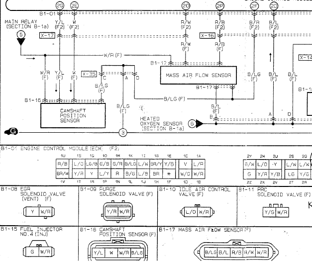
Where do the GM IAT leads go for 94-97 cars? The following diagram/info is from Joe Perez that I found in a different thread. Would the GM IAT go to the "IAT" pin and the "signal ground" pin? Or the "IAT" pin and the "power ground" pin? I feel like this should be simple to figure out, but I don't know enough about how the sensor works to know the answer.

W/R = 12v
R/B = IAT
R/W = MAF (0-5v)
B/L = signal ground
B/LG = power ground
(MAF sensor is the bottom right one in the image below)
JD8 is offline  
Old 09-21-2016, 01:52 AM
  #29  
SADFab Destructive Testing Engineer
iTrader: (5)
 
aidandj's Avatar
 
Join Date: Apr 2014
Location: Beaverton, USA
Posts: 18,642
Total Cats: 1,866
Default

5 speeds blow up on track over 225ft/lbs.

I've seen 2 do it.
aidandj is offline  
Old 09-21-2016, 08:49 AM
  #30  
Junior Member
 
Forrest95M's Avatar
 
Join Date: Jan 2016
Posts: 452
Total Cats: 21
Default

Originally Posted by JD8
Where do the GM IAT leads go for 94-97 cars? The following diagram/info is from Joe Perez that I found in a different thread. Would the GM IAT go to the "IAT" pin and the "signal ground" pin? Or the "IAT" pin and the "power ground" pin? I feel like this should be simple to figure out, but I don't know enough about how the sensor works to know the answer.

W/R = 12v
R/B = IAT
R/W = MAF (0-5v)
B/L = signal ground
B/LG = power ground
(MAF sensor is the bottom right one in the image below)

yes the iat wires should go to the IAT pin and power ground, the order doesn't matter. I believe it isn't based on polarity
Forrest95M is offline  
Old 09-21-2016, 09:02 AM
  #31  
Elite Member
 
x_25's Avatar
 
Join Date: Oct 2013
Location: NorthWest NJ
Posts: 1,821
Total Cats: 141
Default

Originally Posted by Forrest95M
yes the iat wires should go to the IAT pin and power ground, the order doesn't matter. I believe it isn't based on polarity
The IAT sensor is just a thermistor. A resistor that changes resistance based on temperature. So as long as one side goes to the ECU and the other side is grounded it will work.
x_25 is offline  
Old 09-21-2016, 09:14 AM
  #32  
JD8
Junior Member
Thread Starter
iTrader: (2)
 
JD8's Avatar
 
Join Date: May 2016
Location: Maryland
Posts: 237
Total Cats: 25
Default

Originally Posted by Forrest95M
yes the iat wires should go to the IAT pin and power ground, the order doesn't matter. I believe it isn't based on polarity
Why power ground and not sensor ground?

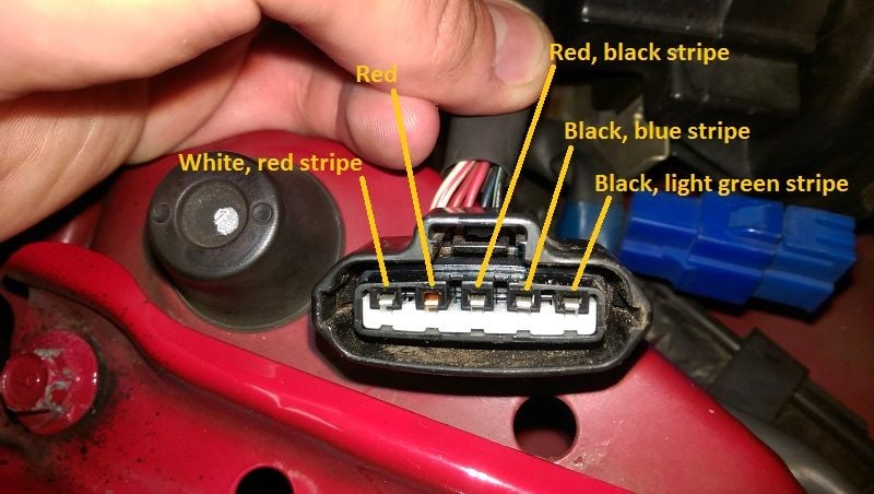
Unfortunately I realized last night that my connector does not match the diagram I linked above so now I am even more lost. Here is my connector:

JD8 is offline  
Old 09-21-2016, 01:16 PM
  #33  
Junior Member
 
Sklr's Avatar
 
Join Date: Nov 2015
Posts: 63
Total Cats: 4
Default

See here:
https://www.diyautotune.com/support/...5-mazda-miata/
Sklr is offline  
Old 09-21-2016, 01:17 PM
  #34  
Boost Czar
iTrader: (62)
 
Braineack's Avatar
 
Join Date: May 2005
Location: Chantilly, VA
Posts: 79,493
Total Cats: 4,080
Default


Braineack is offline  
Old 09-21-2016, 01:37 PM
  #35  
JD8
Junior Member
Thread Starter
iTrader: (2)
 
JD8's Avatar
 
Join Date: May 2016
Location: Maryland
Posts: 237
Total Cats: 25
Default

Thank you both! From the diy site: "Wire one lead of the GM Sensor to the Brown Wire at the AFM Connector, and the other lead of the GM Sensor to the Yellow wire at the AFM Connector."

My connector has neither a brown nor a yellow wire! What is the deal?? But based on their images, they agree with Braineack so that is what I will be doing tonight.

Thanks again guys!
JD8 is offline  
Old 09-21-2016, 01:39 PM
  #36  
JD8
Junior Member
Thread Starter
iTrader: (2)
 
JD8's Avatar
 
Join Date: May 2016
Location: Maryland
Posts: 237
Total Cats: 25
Default

Originally Posted by Braineack
Any idea if this would be accurate for an MS3 with MS3X board built using Frank Westfield's guide? I just happened to pick up an MS EBC solenoid the other day but haven't had the chance to look into hooking it up yet.
JD8 is offline  
Old 09-21-2016, 01:41 PM
  #37  
mkturbo.com
iTrader: (24)
 
shuiend's Avatar
 
Join Date: May 2006
Location: Charleston SC
Posts: 15,177
Total Cats: 1,681
Default

Originally Posted by JD8
Any idea if this would be accurate for an MS3 with MS3X board built using Frank Westfield's guide? I just happened to pick up an MS EBC solenoid the other day but haven't had the chance to look into hooking it up yet.
It depends on how your wired up your db37. I am not familiar enough with Frank's guide to say one way or another.
shuiend is offline  
Old 09-21-2016, 01:53 PM
  #38  
JD8
Junior Member
Thread Starter
iTrader: (2)
 
JD8's Avatar
 
Join Date: May 2016
Location: Maryland
Posts: 237
Total Cats: 25
Default

Originally Posted by shuiend
It depends on how your wired up your db37. I am not familiar enough with Frank's guide to say one way or another.
I actually bought it with the car from Sklr. I will have to do some investigating to find out.
JD8 is offline  
Old 09-21-2016, 02:02 PM
  #39  
Senior Member
iTrader: (1)
 
huesmann's Avatar
 
Join Date: Jul 2014
Location: Silver Spring, MD
Posts: 659
Total Cats: -16
Default

Originally Posted by JD8
Why power ground and not sensor ground?

Unfortunately I realized last night that my connector does not match the diagram I linked above so now I am even more lost. Here is my connector:
Looks to me like the only difference is you have a red wire and the wiring diagram shows a red with white stripe. Are you sure your red wire doesn't have a white stripe?
huesmann is offline  
Old 09-21-2016, 02:18 PM
  #40  
JD8
Junior Member
Thread Starter
iTrader: (2)
 
JD8's Avatar
 
Join Date: May 2016
Location: Maryland
Posts: 237
Total Cats: 25
Default

Originally Posted by huesmann
Looks to me like the only difference is you have a red wire and the wiring diagram shows a red with white stripe. Are you sure your red wire doesn't have a white stripe?
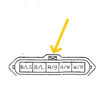
Assuming my red wire is supposed to have a white stripe (I am 100% sure that it does not), then everything would still be switched to the exact opposite side of what the diagram says it would be. Doesn't the box with the "x" in it denote the clip where the plug latches?


If so then the picture I posted and the diagram image are oriented the same and my wires are backwards (mirrored across the y-axis).
JD8 is offline  


Quick Reply: NA Build Plans - ARTech, MS3, and more!


All times are GMT -4. The time now is 08:18 PM.