Did i ever show you guys my...
 03-03-2008, 10:26 AM
#1
2 Props,3 Dildos,& 1 Cat


Thread Starter
iTrader: (8)
Join Date: Jun 2005
Location: Fake Virginia
Posts: 19,338
Total Cats: 573
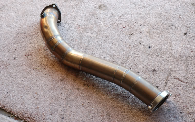
downpipe after I revised it?

if you want, i can take pics of the rest of the exhaust while it's off the car. well, everything but the turbo flange piece. that's a bitch to remove.
if you want, i can take pics of the rest of the exhaust while it's off the car. well, everything but the turbo flange piece. that's a bitch to remove.

Reply
 0
0

0


 03-03-2008, 11:53 AM
#6
2 Props,3 Dildos,& 1 Cat
Thread Starter
iTrader: (8)
Join Date: Jun 2005
Location: Fake Virginia
Posts: 19,338
Total Cats: 573
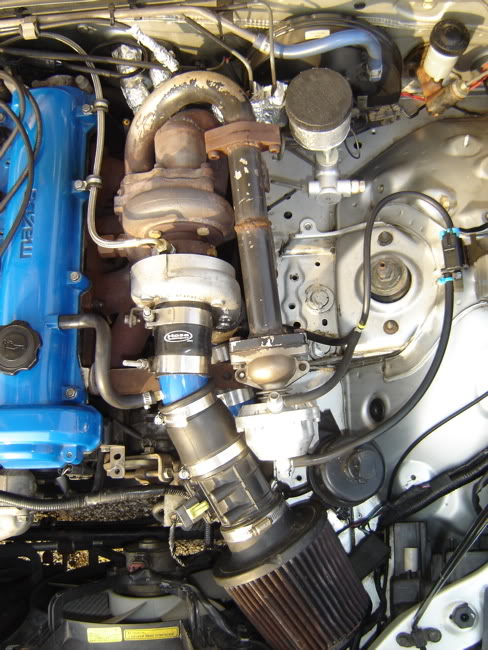
it's actually 2.25 to 3. the 2.25 is the outlet diameter of the turbine housing. It's got a wall to reduce turublence inside the flange.


In an ideal world where I didn't have to put a 90 at the turbo, I would have put the reducer at the flange. next time I guess.
In an ideal world where I didn't have to put a 90 at the turbo, I would have put the reducer at the flange. next time I guess.
Reply
0
0
 03-03-2008, 12:27 PM
#10
2 Props,3 Dildos,& 1 Cat
Thread Starter
iTrader: (8)
Join Date: Jun 2005
Location: Fake Virginia
Posts: 19,338
Total Cats: 573
wait, so run an external gate off the internal gate-hole? wouldn't that defeat the purpose of the external (and higher flowing) gate?
the mani had it on the #4. not first choice but it was what was available at the time.
the mani had it on the #4. not first choice but it was what was available at the time.
Reply
0
0
03-03-2008, 12:47 PM
#12
Boost Pope
iTrader: (8)
Join Date: Sep 2005
Location: Chicago. (The less-murder part.)
Posts: 33,027
Total Cats: 6,592
From Maximum Boost:
The bleed-off must vent from a location where the pulses from all cylinders have been collected. This virtually always means the manifold, close to the turbine mounting flange. Symmetry and easy flow paths are ideals for laying out a wastegate system.
It is vital that exhaust gases be given an easy job of changing direction from the route toward the turbine to the bypass through the wastegate. If flow has any difficulty whatsoever changing direction to exit through the wastegate, the ability to control boost in the higher rev ranges may simply disappear.

Fig. 12-9. The wastegate that does not vent from all cylinders uniformly is a bad idea. Nor should it cause reversal of flow from the turbo, as here.
It is vital that exhaust gases be given an easy job of changing direction from the route toward the turbine to the bypass through the wastegate. If flow has any difficulty whatsoever changing direction to exit through the wastegate, the ability to control boost in the higher rev ranges may simply disappear.
Fig. 12-9. The wastegate that does not vent from all cylinders uniformly is a bad idea. Nor should it cause reversal of flow from the turbo, as here.
Reply
0
0
03-03-2008, 01:02 PM
#13
Way back before the demise of IMSA's GTP class, I distinctly remember seeing wastegates right off the turbine, post manifold flange. The DSM guys are overboring the IWG port and getting 40mm wg in there. I figured since it was post collector/merge that it wouldn't be too bad. It's still pre-turbine blade.
Ok- just looked at t3 turbine housing I have and it doesn't have much more room than 30mm for a port enlargement.
I found a good pictorial: http://www.jakelatham.com/1gDSM/proj...nal_wastegate/
Mitsu turbo has lots more space.
Ok- just looked at t3 turbine housing I have and it doesn't have much more room than 30mm for a port enlargement.
I found a good pictorial: http://www.jakelatham.com/1gDSM/proj...nal_wastegate/
Mitsu turbo has lots more space.
Last edited by m2cupcar; 03-03-2008 at 01:35 PM.
Reply
0
0


 03-03-2008, 01:28 PM
#17
2 Props,3 Dildos,& 1 Cat
Thread Starter
iTrader: (8)
Join Date: Jun 2005
Location: Fake Virginia
Posts: 19,338
Total Cats: 573
From Maximum Boost:
The bleed-off must vent from a location where the pulses from all cylinders have been collected. This virtually always means the manifold, close to the turbine mounting flange. Symmetry and easy flow paths are ideals for laying out a wastegate system.
It is vital that exhaust gases be given an easy job of changing direction from the route toward the turbine to the bypass through the wastegate. If flow has any difficulty whatsoever changing direction to exit through the wastegate, the ability to control boost in the higher rev ranges may simply disappear.
Fig. 12-9. The wastegate that does not vent from all cylinders uniformly is a bad idea. Nor should it cause reversal of flow from the turbo, as here.
but my boost stability says otherwise. the hardest place to control boost is low boost because you require the most flow through the wastegate.
with a $5 mechanical ball 'n spring valve here's what I get:

i'd say there's no wastegate problem here.

Reply
0
0
04-21-2008, 11:58 AM
#19
Did you buy that transition from acestainless y8s?
http://acestainless.com/index.php?ac...&productId=572
Looks like i'll be building my own DP, modeling it slightly after your example. (simple)
http://acestainless.com/index.php?ac...&productId=572
Looks like i'll be building my own DP, modeling it slightly after your example. (simple)
Reply
0
0
04-21-2008, 01:59 PM
#20
2 Props,3 Dildos,& 1 Cat
Thread Starter
iTrader: (8)
Join Date: Jun 2005
Location: Fake Virginia
Posts: 19,338
Total Cats: 573
www.verociousmotorsports.com is where i got my transition. 2-3" and cut it at 2-1/4" to fit my turbine housing exit
Reply
0
0


