TDR i/c allows way more air to the radiator
 07-13-2009, 09:18 PM
#61
2 Props,3 Dildos,& 1 Cat


iTrader: (8)
Join Date: Jun 2005
Location: Fake Virginia
Posts: 19,338
Total Cats: 573
very hard for manufacturability, but I would like to see someone just flood the space on the intake charge end of the core with some kind of epoxy or molten aluminum to smooth it out.

Reply
 0
0

0
 07-15-2009, 12:20 PM
#65

Ha, this is going to be my first post as a newb, but...
With those delta fins, wouldn't it be closer to ideal to have them be half rounds? As it is if you look at it you are getting 3/4ths the flow funneled through half of them, while 1/4 of the flow is going through the other half. (I am talking about external flow through the IC here). I know in actuality, you are still going to get reversion, so it isn't going to go precisely like that, but if you want to decrease your CD, that reversion is killing you. Half rounds really would be better at the leading edge, with the trailing edge getting more of a taper (although from a manufacturing perspective, I wouldn't expect better than half rounds at the tail end either.) At the very least they could have done the delta fins in such a way that the ones that essentially funneled 3/4 of the air in, would have had the same funnel going out, but instead the ones that got 1/4 of the air in get the funnel out. That being said, the deltas are reasonably rounded, so again, maybe not that huge of a difference.
Internally, I like the epoxy flooding idea, but that takes you to the flat plate that you had outside, if you want to get similarly crazy with internal flow, you would want it raised in between to deflect the flow through the IC channels. (Styrofoam rounds covered in epoxy maybe? Obviously you would want something temperature stable and light, maybe really thin aluminum sheet rounds if you felt like cutting the endcaps off and rewelding.)
Reply
0
0
07-15-2009, 01:08 PM
#66
2 Props,3 Dildos,& 1 Cat
iTrader: (8)
Join Date: Jun 2005
Location: Fake Virginia
Posts: 19,338
Total Cats: 573
Ha, this is going to be my first post as a newb, but...
With those delta fins, wouldn't it be closer to ideal to have them be half rounds? As it is if you look at it you are getting 3/4ths the flow funneled through half of them, while 1/4 of the flow is going through the other half. (I am talking about external flow through the IC here). I know in actuality, you are still going to get reversion, so it isn't going to go precisely like that, but if you want to decrease your CD, that reversion is killing you. Half rounds really would be better at the leading edge, with the trailing edge getting more of a taper (although from a manufacturing perspective, I wouldn't expect better than half rounds at the tail end either.) At the very least they could have done the delta fins in such a way that the ones that essentially funneled 3/4 of the air in, would have had the same funnel going out, but instead the ones that got 1/4 of the air in get the funnel out. That being said, the deltas are reasonably rounded, so again, maybe not that huge of a difference.
Internally, I like the epoxy flooding idea, but that takes you to the flat plate that you had outside, if you want to get similarly crazy with internal flow, you would want it raised in between to deflect the flow through the IC channels. (Styrofoam rounds covered in epoxy maybe? Obviously you would want something temperature stable and light, maybe really thin aluminum sheet rounds if you felt like cutting the endcaps off and rewelding.)
With those delta fins, wouldn't it be closer to ideal to have them be half rounds? As it is if you look at it you are getting 3/4ths the flow funneled through half of them, while 1/4 of the flow is going through the other half. (I am talking about external flow through the IC here). I know in actuality, you are still going to get reversion, so it isn't going to go precisely like that, but if you want to decrease your CD, that reversion is killing you. Half rounds really would be better at the leading edge, with the trailing edge getting more of a taper (although from a manufacturing perspective, I wouldn't expect better than half rounds at the tail end either.) At the very least they could have done the delta fins in such a way that the ones that essentially funneled 3/4 of the air in, would have had the same funnel going out, but instead the ones that got 1/4 of the air in get the funnel out. That being said, the deltas are reasonably rounded, so again, maybe not that huge of a difference.
Internally, I like the epoxy flooding idea, but that takes you to the flat plate that you had outside, if you want to get similarly crazy with internal flow, you would want it raised in between to deflect the flow through the IC channels. (Styrofoam rounds covered in epoxy maybe? Obviously you would want something temperature stable and light, maybe really thin aluminum sheet rounds if you felt like cutting the endcaps off and rewelding.)
yes you would want funnel shapes in the end plates rather than flat. that's hard though.
interesting picture:
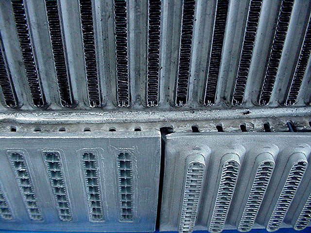
interesting article from which it came:
ARE Cooling (Aluminium Radiators & Engineering P/L)
Reply
0
0
07-15-2009, 01:11 PM
#67
Former Vendor
iTrader: (31)

Join Date: Nov 2006
Location: Sunnyvale, CA
Posts: 15,442
Total Cats: 2,100
Ha, this is going to be my first post as a newb, but...
With those delta fins, wouldn't it be closer to ideal to have them be half rounds? As it is if you look at it you are getting 3/4ths the flow funneled through half of them, while 1/4 of the flow is going through the other half. (I am talking about external flow through the IC here). I know in actuality, you are still going to get reversion, so it isn't going to go precisely like that, but if you want to decrease your CD, that reversion is killing you. Half rounds really would be better at the leading edge, with the trailing edge getting more of a taper (although from a manufacturing perspective, I wouldn't expect better than half rounds at the tail end either.) At the very least they could have done the delta fins in such a way that the ones that essentially funneled 3/4 of the air in, would have had the same funnel going out, but instead the ones that got 1/4 of the air in get the funnel out. That being said, the deltas are reasonably rounded, so again, maybe not that huge of a difference.
Internally, I like the epoxy flooding idea, but that takes you to the flat plate that you had outside, if you want to get similarly crazy with internal flow, you would want it raised in between to deflect the flow through the IC channels. (Styrofoam rounds covered in epoxy maybe? Obviously you would want something temperature stable and light, maybe really thin aluminum sheet rounds if you felt like cutting the endcaps off and rewelding.)
With those delta fins, wouldn't it be closer to ideal to have them be half rounds? As it is if you look at it you are getting 3/4ths the flow funneled through half of them, while 1/4 of the flow is going through the other half. (I am talking about external flow through the IC here). I know in actuality, you are still going to get reversion, so it isn't going to go precisely like that, but if you want to decrease your CD, that reversion is killing you. Half rounds really would be better at the leading edge, with the trailing edge getting more of a taper (although from a manufacturing perspective, I wouldn't expect better than half rounds at the tail end either.) At the very least they could have done the delta fins in such a way that the ones that essentially funneled 3/4 of the air in, would have had the same funnel going out, but instead the ones that got 1/4 of the air in get the funnel out. That being said, the deltas are reasonably rounded, so again, maybe not that huge of a difference.
Internally, I like the epoxy flooding idea, but that takes you to the flat plate that you had outside, if you want to get similarly crazy with internal flow, you would want it raised in between to deflect the flow through the IC channels. (Styrofoam rounds covered in epoxy maybe? Obviously you would want something temperature stable and light, maybe really thin aluminum sheet rounds if you felt like cutting the endcaps off and rewelding.)

Reply
0
0


 07-15-2009, 01:34 PM
#69
Boost Czar

iTrader: (62)
Join Date: May 2005
Location: Chantilly, VA
Posts: 79,501
Total Cats: 4,079
I bought it thinking it was a standard tube and fin. I paid $58 shipped and sold the current one for $45...I'm not complaining. I'm curious to test out the airflow through with the fans running like Jason did.
Reply
0
0


 .
07-18-2009, 03:53 PM
.
07-18-2009, 03:53 PM
#75
Boost Czar
iTrader: (62)
Join Date: May 2005
Location: Chantilly, VA
Posts: 79,501
Total Cats: 4,079
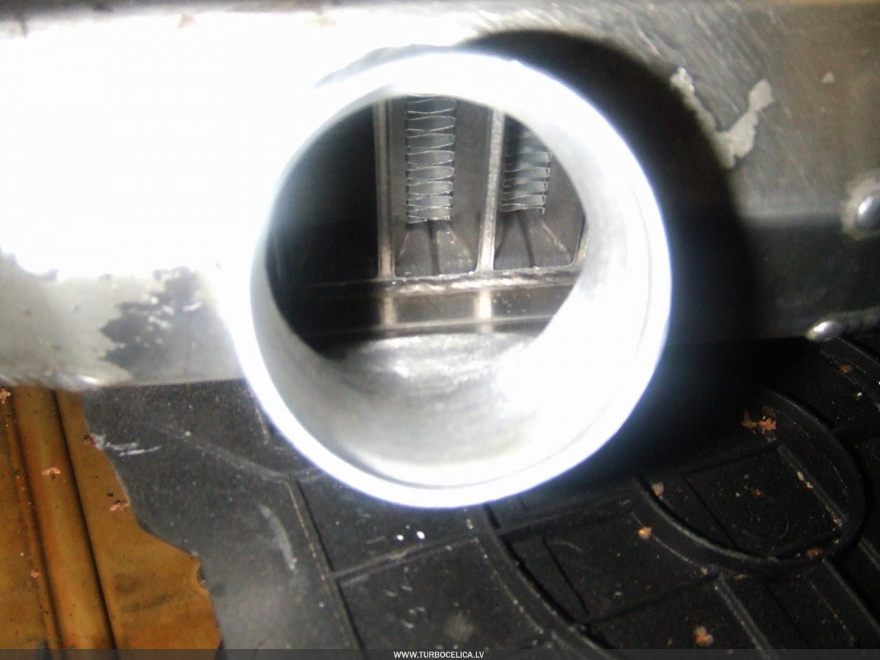
happy times:
.JPG)
.JPG)
I haven't logged yet, but the butt dyno says the turbo is coming on faster. Must have shaved 8-10lbs off the front going to this one.
I noticed my CLT temps on the highway stay around 194*F without the fan on a 82*F day. Before it would have been running 196-200*F with the fan running.
I didn't boost much to notice the aits, ill log a few fourth gear pulls later this week.
Reply
0
0
08-01-2009, 07:44 PM
#77

I have the TDR kit in mine. It does a great job with intercooling. When the pipe from the turbo is quite hot, the pipe to the intake manifold is similar to ambient air temp.
I think part of the explanation is the ducting that causes all air to pass through the IC rather than around it.
Barry
I think part of the explanation is the ducting that causes all air to pass through the IC rather than around it.
Barry
Reply
0
0

Thread
Thread Starter
Forum
Replies
Last Post
bigmackloud
Miata parts for sale/trade
19
01-08-2021 11:24 AM


