
My VVT swap attempt - little different because 1,6 1996 Euro car


 06-17-2013, 09:19 AM
#44
Elite Member
Thread Starter

Join Date: Mar 2006
Location: Schwarzenberg, Germany
Posts: 1,554
Total Cats: 101
Last week I received my BasicMS3 from Reverant (until my Enhanced MS3 will be ready...) so I could re-wire my "old" DIY Frank's PNP style MS3(+x) for the 1,6 to VVT swap.
Here is a little scheme how I did that:
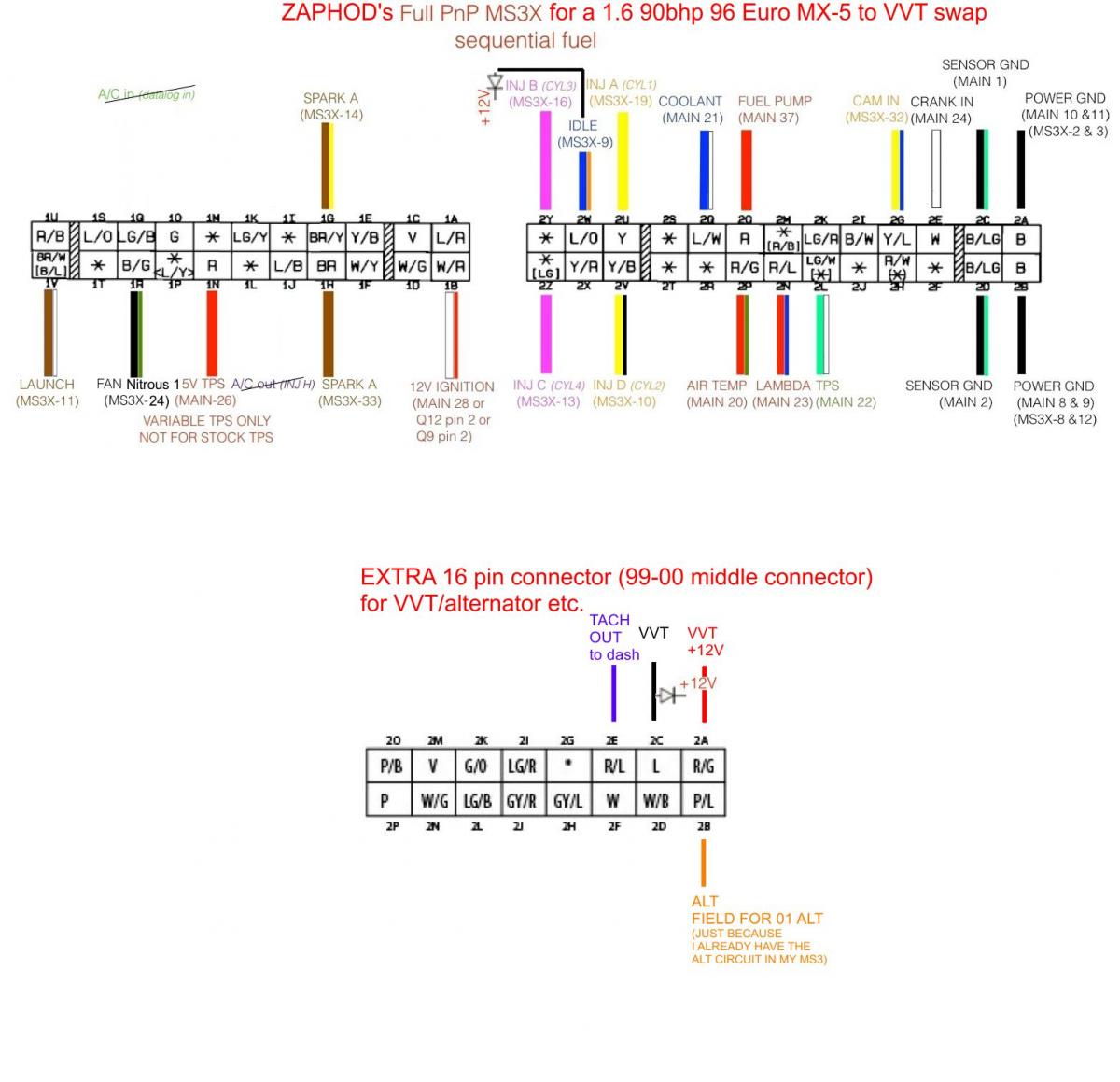
ATM i am unsure if I will swap out the 2001 alternator for an 94-97 unit I have already lying around here, or if I will use my alternator circuit (which was already built into my MS3 case...) and pull a wire to the alt.
Will make an extra wiring loom using the spare 16pin connector in my MS case for VVT +12V and signal, tach out to dash, (maybe the alternator circuit) - did I miss something? Sav could you have a look?
Here is a little scheme how I did that:
ATM i am unsure if I will swap out the 2001 alternator for an 94-97 unit I have already lying around here, or if I will use my alternator circuit (which was already built into my MS3 case...) and pull a wire to the alt.
Will make an extra wiring loom using the spare 16pin connector in my MS case for VVT +12V and signal, tach out to dash, (maybe the alternator circuit) - did I miss something? Sav could you have a look?

Reply
 0
0

0
08-27-2013, 05:00 AM
#45
Elite Member
Thread Starter
Join Date: Mar 2006
Location: Schwarzenberg, Germany
Posts: 1,554
Total Cats: 101
O.K. - let's get the (practical part) of the wiring party started....
First we gonna do the easy bits:
(I took the numerical order from my first post
7. TPS wiring
I made a little adapater harness out of:
AMP JPT 3-position MALE that fit's in the 1.6 harness and the 2001 VVT TPS connector (YAZAKI 7283-1133-10) out of my spare engine harness from my VVT engine:
That was the original sketch: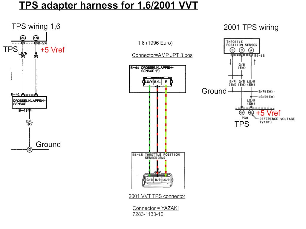
On the bench:
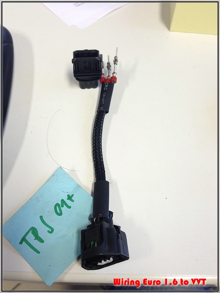
And in the car:
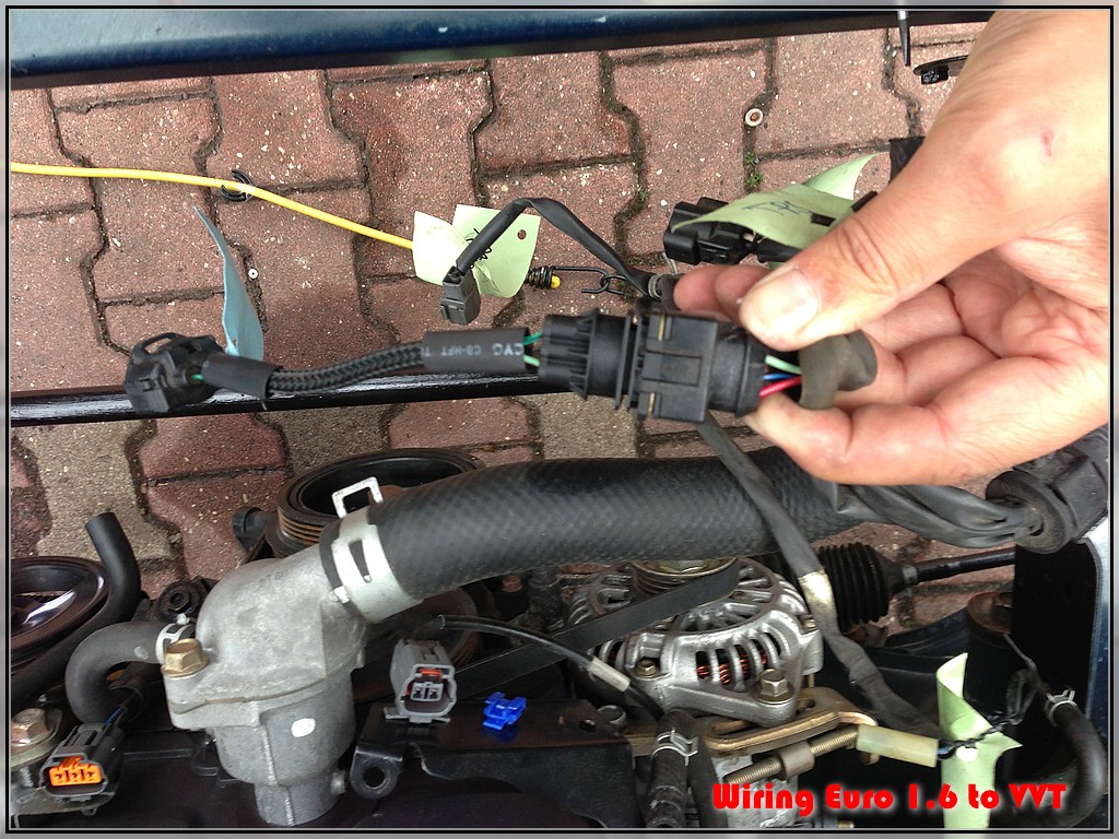
The last pic is for reference - you can see the '01+ wiring colours on the left and the old 1.6 wiring colours on the right (as on the sketch above)
Point Nr. 7 - Check!
First we gonna do the easy bits:
(I took the numerical order from my first post
7. TPS wiring
I made a little adapater harness out of:
AMP JPT 3-position MALE that fit's in the 1.6 harness and the 2001 VVT TPS connector (YAZAKI 7283-1133-10) out of my spare engine harness from my VVT engine:
That was the original sketch:
On the bench:
And in the car:
The last pic is for reference - you can see the '01+ wiring colours on the left and the old 1.6 wiring colours on the right (as on the sketch above)
Point Nr. 7 - Check!
Reply
0
0
08-27-2013, 05:13 AM
#46
Elite Member
Thread Starter
Join Date: Mar 2006
Location: Schwarzenberg, Germany
Posts: 1,554
Total Cats: 101
Next is:
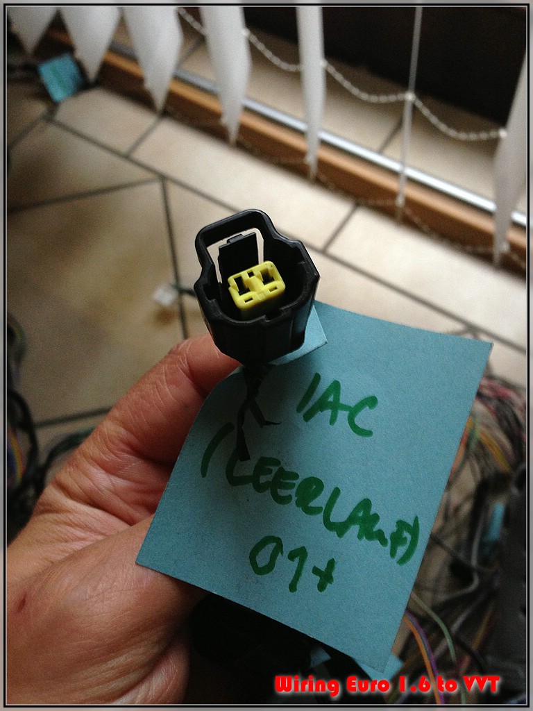
6. IAC wiring
Soooo easy:
At first I thought I would have to do a little adapter harness like that:
That was the original sketch: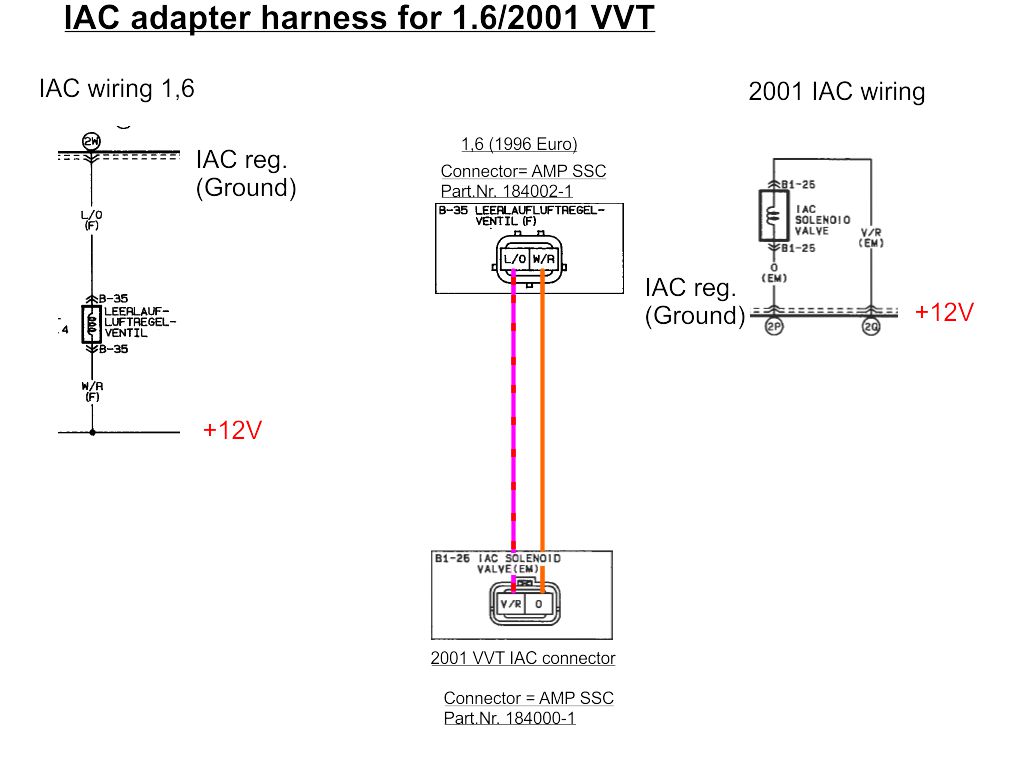
But as you can see - both connectors are AMP SSC connectors - just with different keyways:
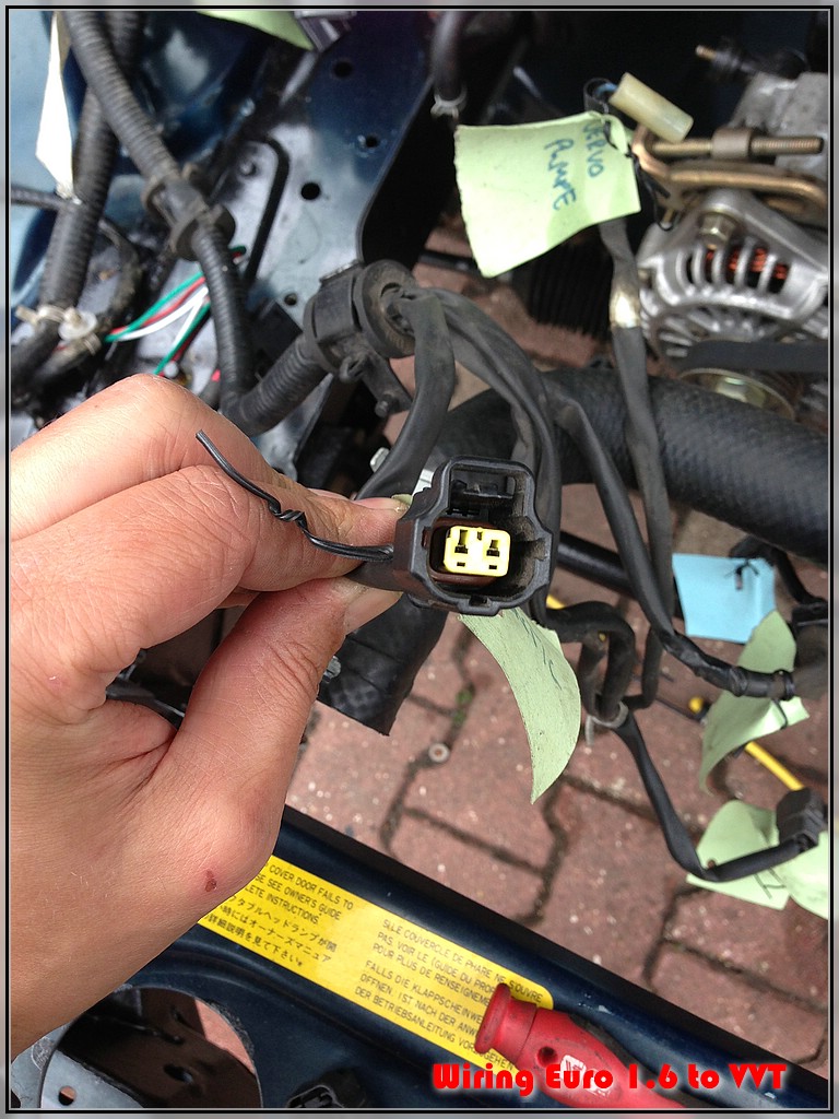
1.6
keyways are in line with the terminals (the connector has a white secontary lock, that was already removed in the first pic)
'01+
keyways are above the terminals
Un-pin the connectors with a tiny flat screwdriver:
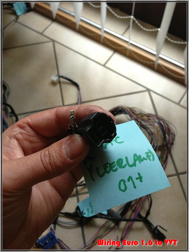
Just plug the new '01 connector housing over the pins of your old 1,6 harness. Done!
Here is what I think should be the correct wiring:
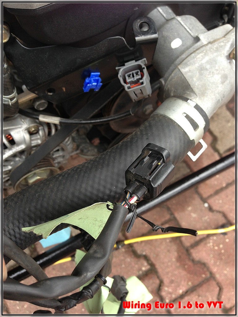
Point Nr. 6 - Check!
6. IAC wiring
Soooo easy:
At first I thought I would have to do a little adapter harness like that:
That was the original sketch:
But as you can see - both connectors are AMP SSC connectors - just with different keyways:
1.6
keyways are in line with the terminals (the connector has a white secontary lock, that was already removed in the first pic)
'01+
keyways are above the terminals
Un-pin the connectors with a tiny flat screwdriver:
Just plug the new '01 connector housing over the pins of your old 1,6 harness. Done!
Here is what I think should be the correct wiring:
Point Nr. 6 - Check!
Reply
0
0
09-03-2013, 08:21 AM
#47
Elite Member
Thread Starter
Join Date: Mar 2006
Location: Schwarzenberg, Germany
Posts: 1,554
Total Cats: 101
Go on...
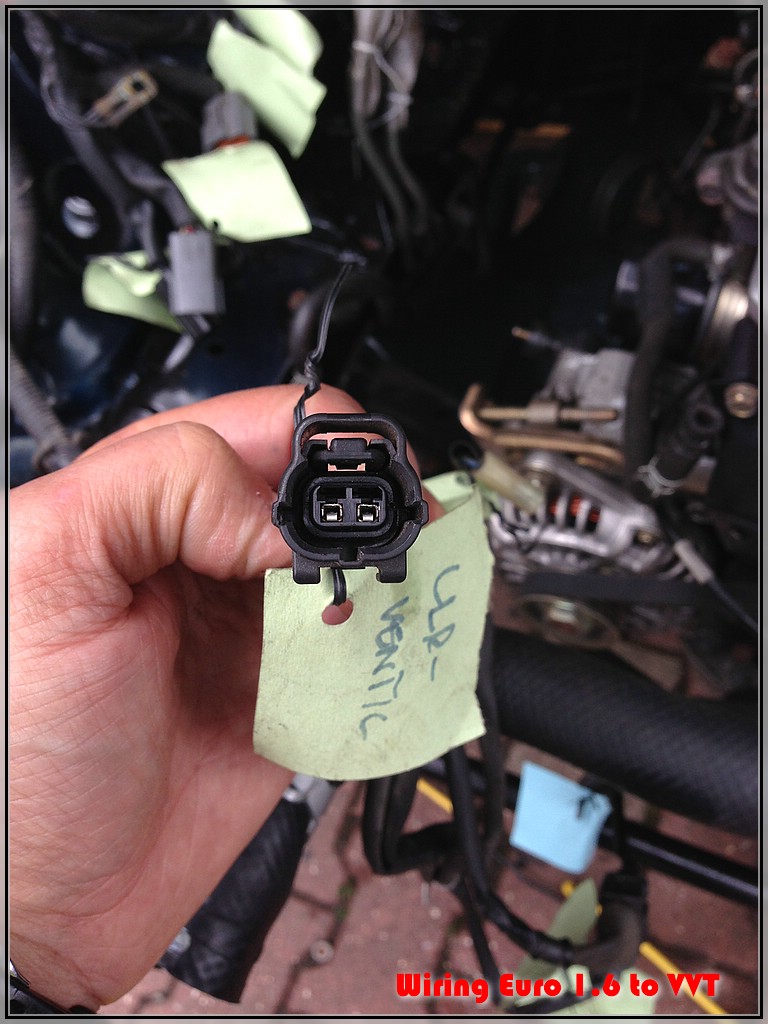
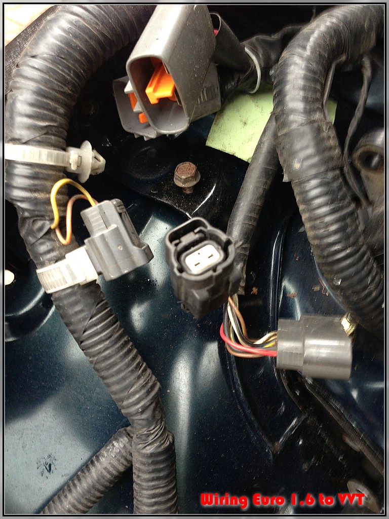
5. CAM/CRANK wiring
again - the original idea for an adapter harness:
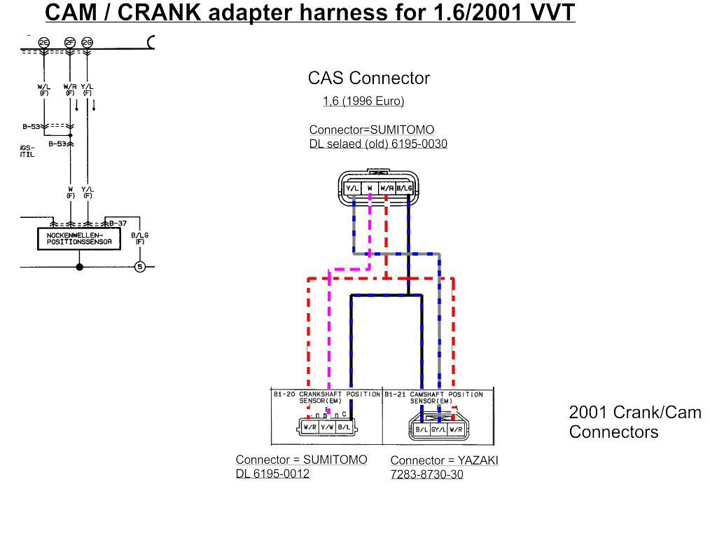
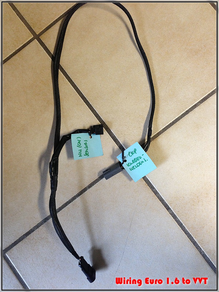
Here is the finished harness (again out of my spare 01 VVT harness)
with the Cam sensor and Crank sensor and a 4 pos. AMP superseal as
connector with the OEM 1.6 harness (the CAS connector will be replaced by the mating female AMP superseal connector)
Harness
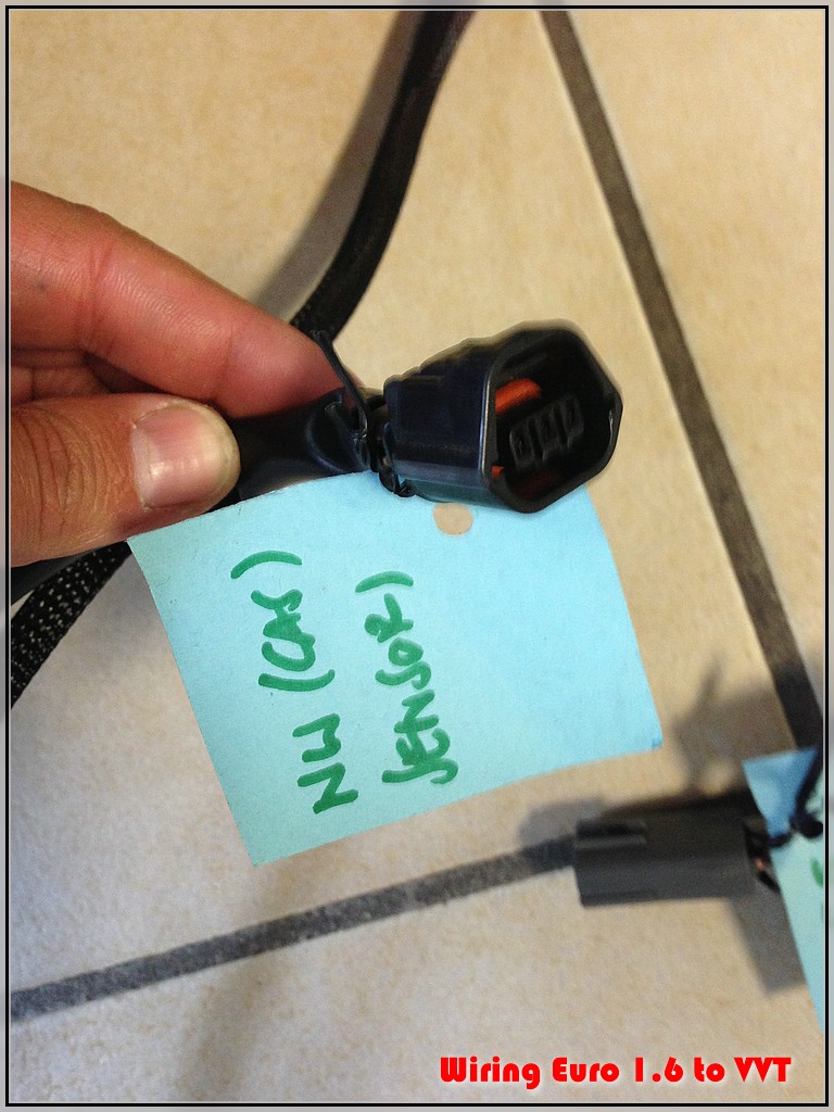
Cam sensor connector:
Crank sensor connector:
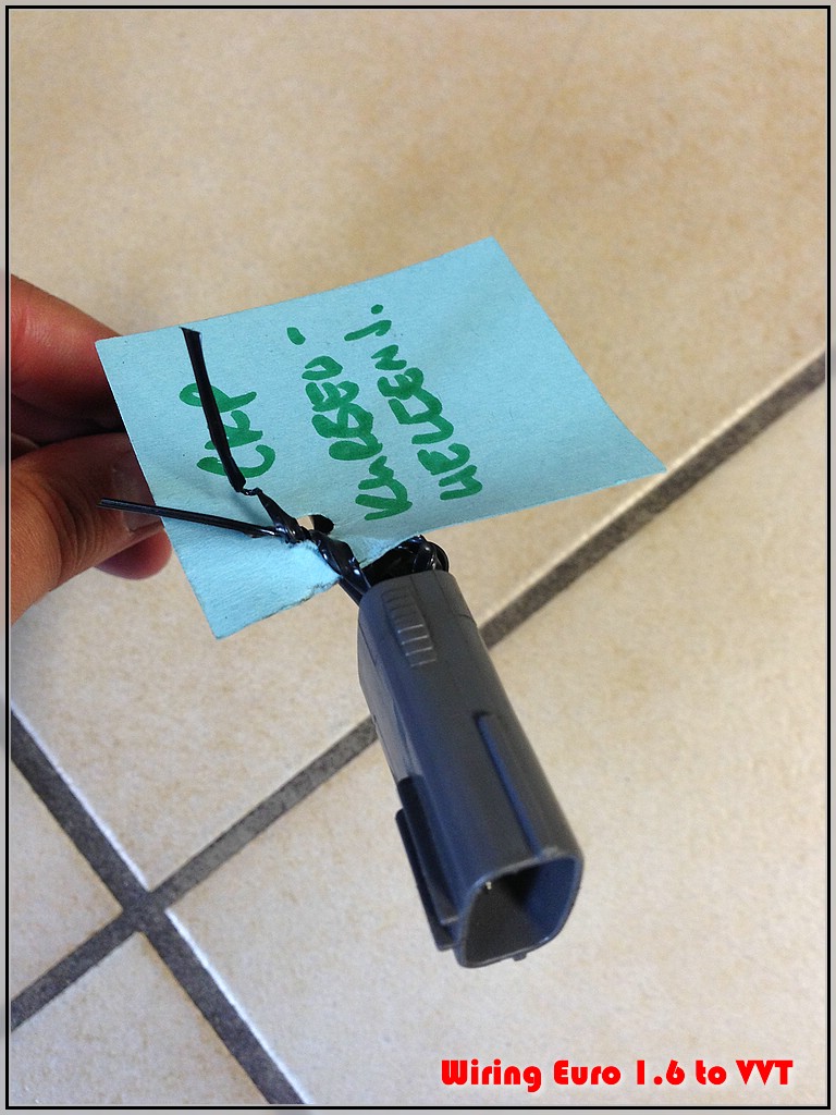
AMP superseal 4pos. male (substitution for CAS connector)
Nr. 5 - done!
5. CAM/CRANK wiring
again - the original idea for an adapter harness:
Here is the finished harness (again out of my spare 01 VVT harness)
with the Cam sensor and Crank sensor and a 4 pos. AMP superseal as
connector with the OEM 1.6 harness (the CAS connector will be replaced by the mating female AMP superseal connector)
Harness
Cam sensor connector:
Crank sensor connector:
AMP superseal 4pos. male (substitution for CAS connector)
Nr. 5 - done!
Reply
0
0
09-03-2013, 10:11 AM
#48
Elite Member
Thread Starter
Join Date: Mar 2006
Location: Schwarzenberg, Germany
Posts: 1,554
Total Cats: 101
The countdown continues...
4. COIL/IGNITER wiring
3. CLT
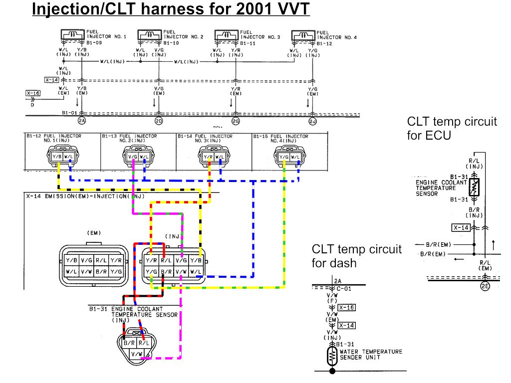
2. Injector / Coolant wiring
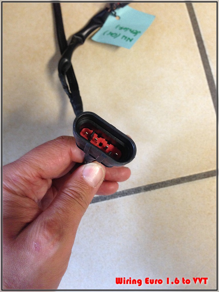
The last harnesses was a bit difficult, it's made out of the OEM '01
injector/coil harness
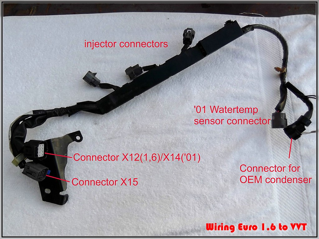
Here is my latest revised sketch of the Coil/igniter harness I made:
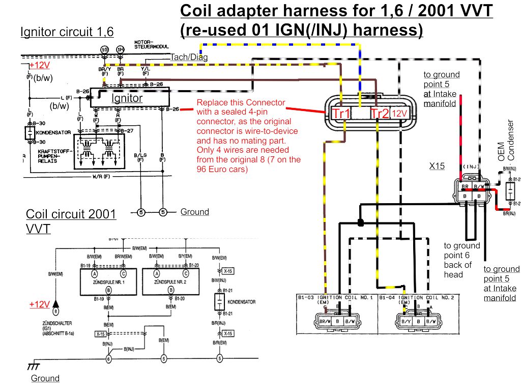
As you can see this harness also uses the connector X15 of the OEM 01 injector/ignition harness to connect to the OEM ground points 5 and 6.
Very difficult to draw a schematic, so I stole a pic of TZ's build here you can see the different ground loops going through the X15 connector to the back of the head (and the condenser there) and to the front of the intake manifold.
From this harness I made a little adapter wiring that connects to the wiring of the ignitor connector with a 4pos. AMP superseal connector (wiring gets cut at the ignitor connctor and replaced with the counterpart of the Superseal connector... (the igintor connector has 8 pos. but only 4 of them are still needed...)
For the injector harness I could use the complete 01 harness ( I only had to re-pin the sequential injector connectors on my OEM Euro 1.6 harness - apart from that everything else is the same, even the CLT wiring to dash and ECU) and will re-use the '01 CLT sensor that integrates both the ECU and Gauge thermistors (gauge thermistor is grounded through the body of the sensor) - the thermistor resistances are the same on both cars 1,6 and '01
Unfortunately I forgot to take pictures of the harness out of the car, so here are some pics on the car.
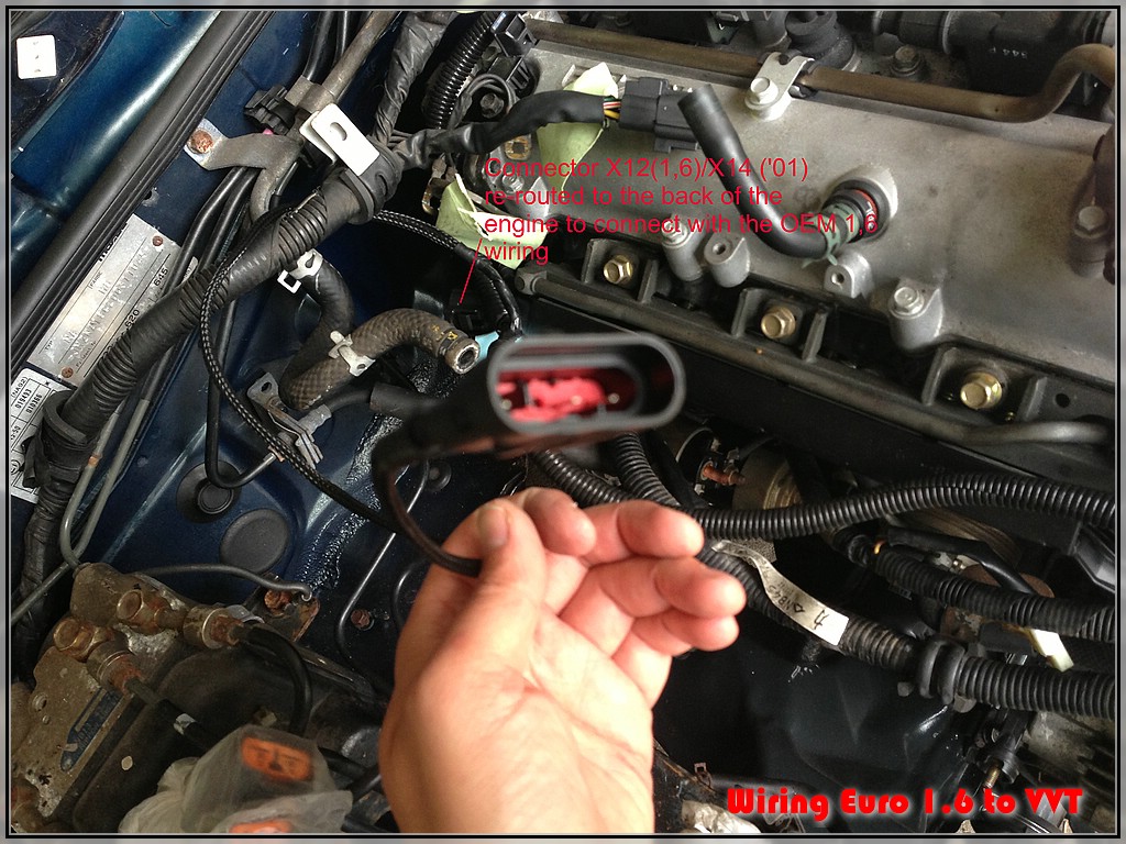
I had to re-route the connector X14 of the '01 harness to the back of the head to meet the connector X12 of the 1,6 wiring - but the connectors are physically the same...
I hope someone understands that gibberish I wrote here - but this harness was quite a difficult task - as I wanted to keep it as plug and play and OEM as possible. I only used the AMP superseal connectors on connectors with no mating OEM parts (connectors that are "wire-to-device" type, like the CAS and the Ignitor connector)
4. COIL/IGNITER wiring
3. CLT
2. Injector / Coolant wiring
The last harnesses was a bit difficult, it's made out of the OEM '01
injector/coil harness
Here is my latest revised sketch of the Coil/igniter harness I made:
As you can see this harness also uses the connector X15 of the OEM 01 injector/ignition harness to connect to the OEM ground points 5 and 6.
Very difficult to draw a schematic, so I stole a pic of TZ's build here you can see the different ground loops going through the X15 connector to the back of the head (and the condenser there) and to the front of the intake manifold.
From this harness I made a little adapter wiring that connects to the wiring of the ignitor connector with a 4pos. AMP superseal connector (wiring gets cut at the ignitor connctor and replaced with the counterpart of the Superseal connector... (the igintor connector has 8 pos. but only 4 of them are still needed...)
For the injector harness I could use the complete 01 harness ( I only had to re-pin the sequential injector connectors on my OEM Euro 1.6 harness - apart from that everything else is the same, even the CLT wiring to dash and ECU) and will re-use the '01 CLT sensor that integrates both the ECU and Gauge thermistors (gauge thermistor is grounded through the body of the sensor) - the thermistor resistances are the same on both cars 1,6 and '01
Unfortunately I forgot to take pictures of the harness out of the car, so here are some pics on the car.
I had to re-route the connector X14 of the '01 harness to the back of the head to meet the connector X12 of the 1,6 wiring - but the connectors are physically the same...
I hope someone understands that gibberish I wrote here - but this harness was quite a difficult task - as I wanted to keep it as plug and play and OEM as possible. I only used the AMP superseal connectors on connectors with no mating OEM parts (connectors that are "wire-to-device" type, like the CAS and the Ignitor connector)
Reply
0
0
09-06-2013, 04:26 PM
#49

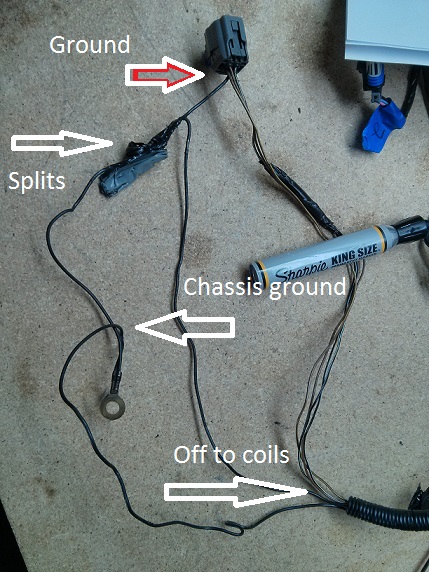
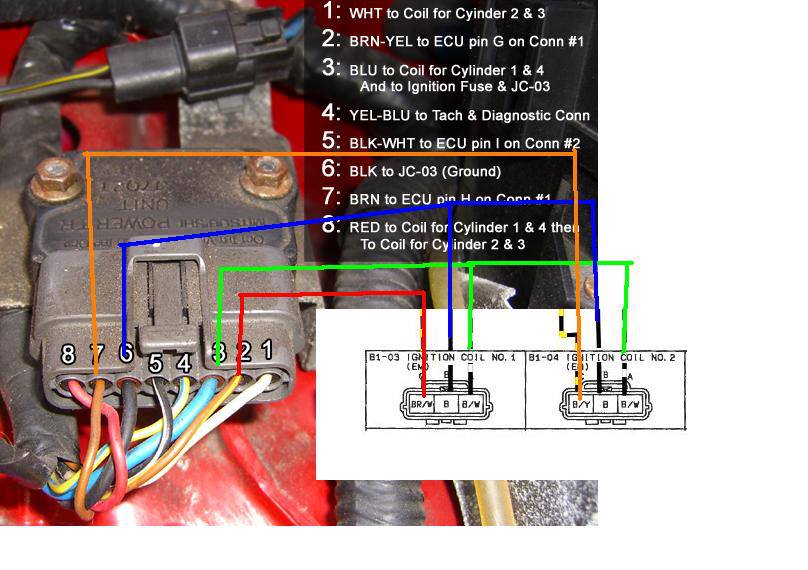
Thanks for all this info, everything but the injector/clt harness worked for my usdm 91 vvt swap, since I had batch injection originally. The coils were slightly different too, as I had ground right at the igniter I could use so I didn't need the ground from the condenser, I just gutted the igniter and ran the 4 wires from there to the stock 01 coils. Here's the "for dummies" diagram I used for the coil wiring, same thing really just usdm version for reference. Other than that I just had to wire my injector/clt harness for sequential. Everything else was exactly the same. Thanks again!
Last edited by Red91; 09-06-2013 at 04:38 PM.
Reply
0
0
09-07-2013, 04:55 AM
#50
Junior Member

Join Date: Aug 2011
Posts: 56
Total Cats: 0
Ditto the above! Thanks for these wiring diagrams, they are what I used for my VVT swap into my mk1 1990. For the 01 coils I also gutted the mk1 igniter and soldered the wires to the pins as above but I just ground the coils directly to the head rather than the ground in the igniter? I also soldered pins 4 and 5 together in the igniter and connected the tach output on my Megasquirt to the black white wire at the ecu harness (which goes to pin5 at the igniter), this then drives the rev counter using the original wiring.
Reply
0
0
 09-16-2013, 05:10 AM
#52
Elite Member
Thread Starter
Join Date: Mar 2006
Location: Schwarzenberg, Germany
Posts: 1,554
Total Cats: 101
To put an (lucky) end to this thread... all my research work seems to have paid,
the car runs....
We had some minor glitches to get the car starting (one was a leaking injector, nice to remove the bloody intake manifold again... )
)
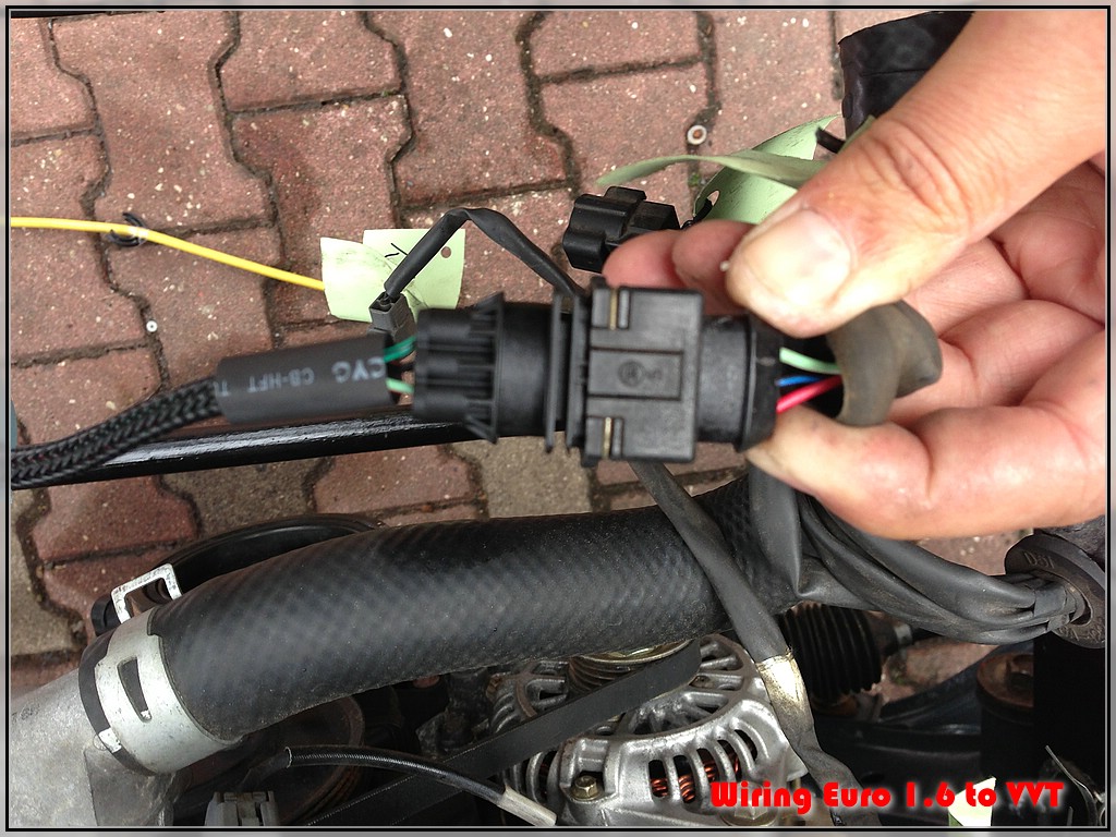
One thing that really gave us a hrad time was the fact, that we got no cam signal at the first try...
See here:
According to this picture with the little pic out of the German wiring schematics we should be getting the CAM signal in at pins 2E and 2F at the ECU - the signal is spliced into two wires at the connector B35 according to the wiring schematics. After we checked the continuity on the wires we only got continuity at 2F.... So in swapped the pins 2E and 2F on the ECU connector and the car started... (Well it ran llike ****... because the tank was totally empty... )
)
So after we got some fuel into the tank...
Well no exhaust, no intake (way too little hydraulic fluid in the PS reservoir - hence the squealing)
But after all - it RUNS!
Thanks again for all your help and suggestions!
the car runs....
We had some minor glitches to get the car starting (one was a leaking injector, nice to remove the bloody intake manifold again...
)One thing that really gave us a hrad time was the fact, that we got no cam signal at the first try...
See here:
According to this picture with the little pic out of the German wiring schematics we should be getting the CAM signal in at pins 2E and 2F at the ECU - the signal is spliced into two wires at the connector B35 according to the wiring schematics. After we checked the continuity on the wires we only got continuity at 2F.... So in swapped the pins 2E and 2F on the ECU connector and the car started... (Well it ran llike ****... because the tank was totally empty...
)So after we got some fuel into the tank...
Well no exhaust, no intake (way too little hydraulic fluid in the PS reservoir - hence the squealing)
But after all - it RUNS!
Thanks again for all your help and suggestions!
Reply
0
0

 09-16-2013, 08:55 AM
#54
Elite Member
Thread Starter
Join Date: Mar 2006
Location: Schwarzenberg, Germany
Posts: 1,554
Total Cats: 101
Greets
Reply
0
0
08-05-2014, 08:38 AM
#55

Go on...
5. CAM/CRANK wiring
again - the original idea for an adapter harness:
Here is the finished harness (again out of my spare 01 VVT harness)
with the Cam sensor and Crank sensor and a 4 pos. AMP superseal as
connector with the OEM 1.6 harness (the CAS connector will be replaced by the mating female AMP superseal connector)
Harness
Cam sensor connector:
Crank sensor connector:
AMP superseal 4pos. male (substitution for CAS connector)
Nr. 5 - done!
I'm digging this old thread, but did you used shielded wire on your harness for the Cam and Crank signal ?
Reply
0
0

Thread
Thread Starter
Forum
Replies
Last Post
AlwaysBroken
Engine Performance
4
09-04-2015 01:35 PM


