help 01-05 coils msII sharing sensors
 08-19-2011, 09:05 AM
#1

forgive me for i am a noob
i bought fully functioning assembled ms2 used. it was previously running a sr20 with a ford EDIS module and it ran 4 individual coils that fit directly over the plugs.
i have some questions about how im supposed to set this megasquirt up internaly to drive the 2 OE coils directly without an external ignition module (such as the edis module). id like to keep as much of the factory sensors as possible. i will be using the gm IAT for obvious reasons but id like to keep the CLT and crank sensor original im hoping to do this all in parallell with the stock ecu because it drives the tachometer and alternator.
i was thinking about doing that mod "Bosch BIP373 Coil Driver Mod Kit" seems like it would do the trick. but apparently i have to remove another piece of hardware to make it fit....i dont even know what that thing is and if ill need it. and since this thing was previouisly set up for edis what mods do i have to UN-DO.
im not sure how to figure out if the 01-05 coils use a 5 volt signal or 12 volt. i have a feeling its only 5 volts but even if it is i still dont know what differences that makes in the internals of the megasquirt.
idk if some of you guys can just look at this thing and tell what needs to be done it does not seem too complex i know if i assembled it i would have a better understanding of what everything is
i really wanted to utilize all of the factory hardware but i understand nothing is permanent. one of my biggest concerns is i just want my gauge cluster to work. this car is so close to being complete im willing to do whatever necessary to make it run i have my engine harness unwrapped and laying on my floor ready for modification i just need a guide in the right direction with this engine management thing.
(flame suit on)

Reply
 0
0

0
 08-19-2011, 09:27 AM
#3
how do i go about setting that up? u make it seem really simple. like connect the positive hole on the circuit board to a hole on the db37 connector? it cant be that simple.
Reply
0
0
08-19-2011, 09:36 AM
#4
Elite Member
iTrader: (1)

Join Date: Jun 2006
Location: Warrington/Birmingham
Posts: 2,642
Total Cats: 42
it's not that simple, but not that far off.
You know what might be a good idea? Reading the manual....
http://www.msextra.com/doc/ms2extra/MS2-Extra_Miata.htm
Tells you exactly how to setup the igntion outputs right there (and the cam/crank signal inputs).
There's no need to keep the OEM ECU to drive the alternator & tacho either. MS is more than capable of doing both, again RTFM.
Reply
0
0
08-19-2011, 10:21 AM
#5
Boost Pope


iTrader: (8)
Join Date: Sep 2005
Location: Chicago. (The less-murder part.)
Posts: 33,046
Total Cats: 6,607
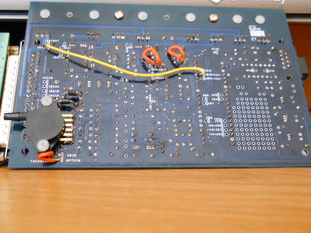
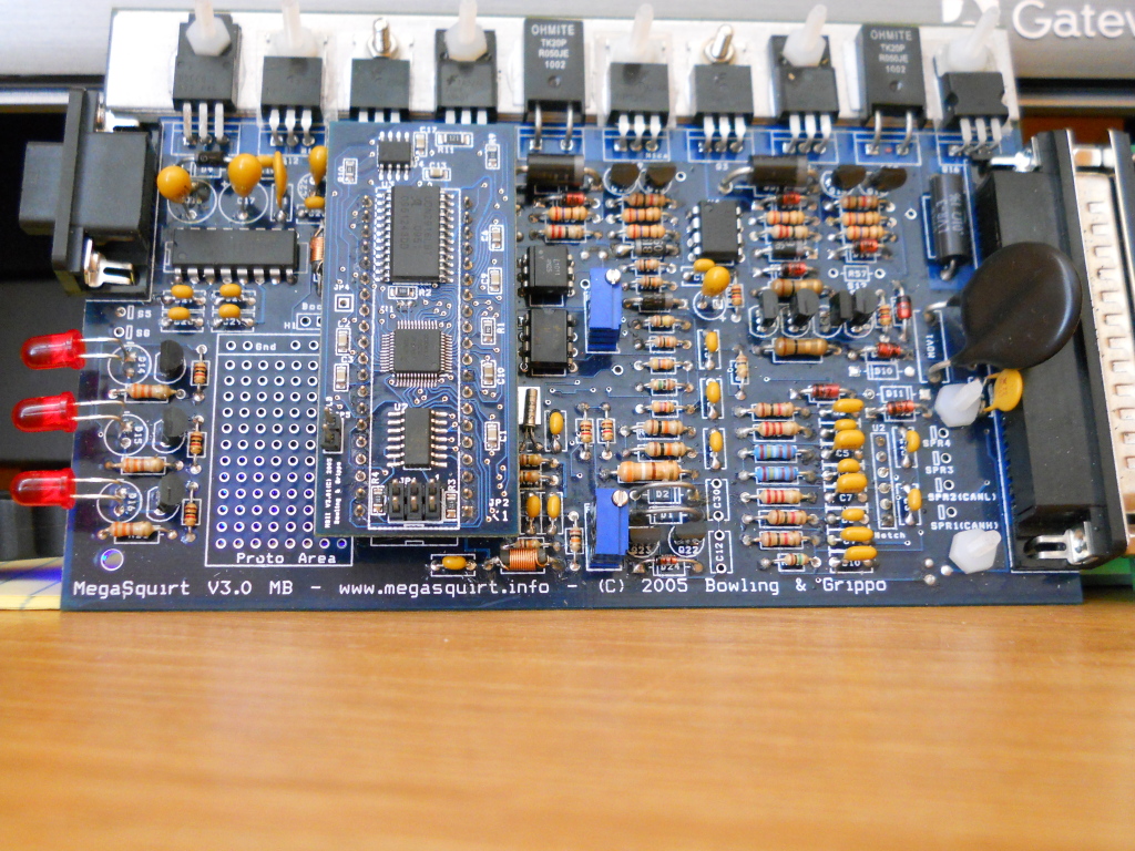
This Article describes how to do the physical modifications. Scroll down to "Option 1: Spark Output to factory Miata ignitors"
Note that this article is written with the MS1 and an NA in mind, so some of the info will not be relevant to your car, but the basics of the spark output driver are the same.
Reply
0
0
08-22-2011, 01:31 PM
#6
Yes, that is traditionally how cars with two channel wasted-spark ignition systems are configured to run on Megasquirt. Specifically, D14 (Squirt) is ignition channel A, and D16 (accel) is ignition channel B.
This Article describes how to do the physical modifications. Scroll down to "Option 1: Spark Output to factory Miata ignitors"
Note that this article is written with the MS1 and an NA in mind, so some of the info will not be relevant to your car, but the basics of the spark output driver are the same.
i have a question regarding the modification it gives the option of 270 or 330 ohm resistors . what dictates which one i should use?
and the mod says it only requires 2 resistors but it looks like id have to add a total of 5
3x of the 1k 1/4 watt resistors (i guess 2 of those are supposed to be 270 or 330 ohm)
2x of the 470 ohm 1/4 watt resistors
im having trouble understanding why they would be marked as 1k resistors in the illustration if they are only supposed to be 270 or 330.
thanks for the help guys!
Reply
0
0
08-22-2011, 01:43 PM
#7
Supporting Vendor

iTrader: (33)
Join Date: Jul 2006
Location: atlanta-ish
Posts: 12,659
Total Cats: 134
Joe is referring only to the ignition output mods, which are the green lines in the pic he pointed to. (2) 1/4 watt resistors are required. The exact value is not important. I recommend 100 ohms. The text lists 270 *to* 330 ohms. With most coils, you could likely use any value from 100 ohms (or probably less) to 1000 ohms (or probably more) and have a fine working ignition system.
I recommend 100 ohms because the lower the resistance, the higher the voltage, and some aftermarket coils do better with a real hot signal. However most simply don't care what the voltage on the logic trigger is, so long as there is a trigger within a reasonable range.
I recommend 100 ohms because the lower the resistance, the higher the voltage, and some aftermarket coils do better with a real hot signal. However most simply don't care what the voltage on the logic trigger is, so long as there is a trigger within a reasonable range.

Reply
0
0
08-22-2011, 02:12 PM
#8
Joe is referring only to the ignition output mods, which are the green lines in the pic he pointed to. (2) 1/4 watt resistors are required. The exact value is not important. I recommend 100 ohms. The text lists 270 *to* 330 ohms. With most coils, you could likely use any value from 100 ohms (or probably less) to 1000 ohms (or probably more) and have a fine working ignition system.
I recommend 100 ohms because the lower the resistance, the higher the voltage, and some aftermarket coils do better with a real hot signal. However most simply don't care what the voltage on the logic trigger is, so long as there is a trigger within a reasonable range.
I recommend 100 ohms because the lower the resistance, the higher the voltage, and some aftermarket coils do better with a real hot signal. However most simply don't care what the voltage on the logic trigger is, so long as there is a trigger within a reasonable range.
also one more question im guessing that the miata uses a 5v hall effect sensor right? im guessing so since i think everything else is 5v too.
Reply
0
0
08-23-2011, 03:37 AM
#9
Elite Member
iTrader: (1)
Join Date: Jun 2006
Location: Warrington/Birmingham
Posts: 2,642
Total Cats: 42
The MX5 coils do care what the trigger voltage is. It's 5v, period, run 12v through them and they'll not work. BTDT
A higher resistor delays the onset of this 5v trigger to the coil, whilst it ramps up. Joe has some scope traces of the signal somewhere which is pretty interesting. This is what Ben is on about. you're talking microseconds worth of time though, it's almost inconsequential. Almost.
A higher resistor delays the onset of this 5v trigger to the coil, whilst it ramps up. Joe has some scope traces of the signal somewhere which is pretty interesting. This is what Ben is on about. you're talking microseconds worth of time though, it's almost inconsequential. Almost.
Reply
0
0

Thread
Thread Starter
Forum
Replies
Last Post
Zaphod
MEGAsquirt
47
10-26-2018 11:00 PM
StratoBlue1109
Miata parts for sale/trade
21
09-30-2018 01:09 PM
Greasyman
General Miata Chat
2
09-28-2015 10:44 AM


