Help needed - MS2 3.0 Assembly
 01-23-2013, 10:16 PM
#1
Newb
Thread Starter

Join Date: Mar 2011
Posts: 8
Total Cats: 0
Hi guys,
I picked up a "bargain" MS2 from my forum with the OP claiming it worked fine but couldn't pick up the signal from the back of the CAS.
I've gone through dozens of pages and checked all the mods, the only thing I can see that doesn't look right is that IAC1A goes to some random spot on the board when it should go to JS10 and JS10 should go to 5v through 470ohm resistor.
It was apparently set up for a 1.6 with the below mods:
And I am putting it in an '89 Jap Import with a
If any of the pro's in here could take a quick look for me and let me know if IAC1A needs to be modded again and also if there is anything else that looks out of place for my setup I'd really appreciate it.
Cheers,
Dre.
I picked up a "bargain" MS2 from my forum with the OP claiming it worked fine but couldn't pick up the signal from the back of the CAS.
I've gone through dozens of pages and checked all the mods, the only thing I can see that doesn't look right is that IAC1A goes to some random spot on the board when it should go to JS10 and JS10 should go to 5v through 470ohm resistor.
It was apparently set up for a 1.6 with the below mods:
- PWM IAC modkit
- Fan control relay mod
- Boost control modkit
- Latest ignition circuit mods
And I am putting it in an '89 Jap Import with a
- greddy turbo kit
- aircon
- power steer
- stock ignition
- auto TPS
If any of the pro's in here could take a quick look for me and let me know if IAC1A needs to be modded again and also if there is anything else that looks out of place for my setup I'd really appreciate it.
Cheers,
Dre.

Reply
 0
0

0

 01-24-2013, 09:06 AM
#4
Boost Czar


iTrader: (62)
Join Date: May 2005
Location: Chantilly, VA
Posts: 79,508
Total Cats: 4,080
okay, it looks correctly modded to run the CAS inputs on MS2...but I'm unsure on a few things.
first:
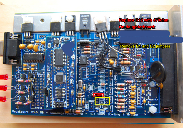
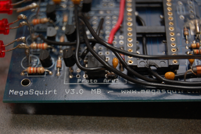
is the resistor on R39 just pulled up on one side? If so, remove it and jump R39 with a solid wire.
Otherwise it looks like it attaches to that blue resistor (IIRC R52) which I'm not sure I understand. On that subject, I dont see the need for the resistor between r48 and r50, and the one from r42 to where ever it may go.
second:
looks like you have the idle pwn mod installed (but fix the r39 jumper)
and the high driver circuit going out spare 4 for the fuel pump activation. So make sure you remove your ST_SIGN fuse before you turn on the ignition.
third:
not sure what the yellow wire off the ms2 cpu daughtboard is doing/going. It might be modded for knock input?
fourth:
I think the IAC1A is wired where it is to put the cam input through a second opto circuit (the white component on U7). Which is better than directly into JS10. Never seen it done that way, but judging by that additional capacitor and the extra resistors in the spots they are, I'm pretty certain that's the deal.
lastly:
the only other thing I suggest is modding the harness to run your a/c switch in and back out of the MS, loading the lastest gslender firmware, and allowing MS to have a/c feed forward abilities for better idle control.
first:
is the resistor on R39 just pulled up on one side? If so, remove it and jump R39 with a solid wire.
Otherwise it looks like it attaches to that blue resistor (IIRC R52) which I'm not sure I understand. On that subject, I dont see the need for the resistor between r48 and r50, and the one from r42 to where ever it may go.
second:
looks like you have the idle pwn mod installed (but fix the r39 jumper)
and the high driver circuit going out spare 4 for the fuel pump activation. So make sure you remove your ST_SIGN fuse before you turn on the ignition.
third:
not sure what the yellow wire off the ms2 cpu daughtboard is doing/going. It might be modded for knock input?
fourth:
I think the IAC1A is wired where it is to put the cam input through a second opto circuit (the white component on U7). Which is better than directly into JS10. Never seen it done that way, but judging by that additional capacitor and the extra resistors in the spots they are, I'm pretty certain that's the deal.
lastly:
the only other thing I suggest is modding the harness to run your a/c switch in and back out of the MS, loading the lastest gslender firmware, and allowing MS to have a/c feed forward abilities for better idle control.
Reply
0
0
01-29-2013, 01:44 AM
#5
Newb
Thread Starter
Join Date: Mar 2011
Posts: 8
Total Cats: 0
Hi Scott, sorry for taking so long to get back to you... we had a 3 day weekend here in Aus (Australia Day holiday  )
)
Anyways, a few clarifications/questions below in red:
Thanks again for your help, looking forward to throwing the Wolf in the bin.
)Anyways, a few clarifications/questions below in red:
okay, it looks correctly modded to run the CAS inputs on MS2...but I'm unsure on a few things.
first:
is the resistor on R39 just pulled up on one side? If so, remove it and jump R39 with a solid wire. Resistor in R39 isn't pulled up, just a bit bent. Should I leave it as is or remove the resistor and jump with a solid wire?
Otherwise it looks like it attaches to that blue resistor (IIRC R52) which I'm not sure I understand. It doesn't attach to the blue one, just the way the photo was taken...
On that subject, I dont see the need for the resistor between r48 and r50, and the one from r42 to where ever it may go. Should I remove these?
second:
looks like you have the idle pwn mod installed (but fix the r39 jumper)
and the high driver circuit going out spare 4 for the fuel pump activation. So make sure you remove your ST_SIGN fuse before you turn on the ignition.My car has a Wolf 3D plug and play with AFM delete so there is already a wire running back from the AFM to the ECU to keep the fuel pump running. Will I still need this wire with the MS2?
third:
not sure what the yellow wire off the ms2 cpu daughtboard is doing/going. It might be modded for knock input? It runs to the same pin on the underside of the daughter board I really can't see it doing anything.
fourth:
I think the IAC1A is wired where it is to put the cam input through a second opto circuit (the white component on U7). Which is better than directly into JS10. Never seen it done that way, but judging by that additional capacitor and the extra resistors in the spots they are, I'm pretty certain that's the deal. The previous owner couldn't get a cam signal when plugged into a STIM. Should I plug it into the car as is, see if it works and if it doesn�t rewire IAC1A -> JS10 -> 470 ohm resistor -> 5v?
lastly:
the only other thing I suggest is modding the harness to run your a/c switch in and back out of the MS, loading the lastest gslender firmware, and allowing MS to have a/c feed forward abilities for better idle control.
Reply
0
0
01-29-2013, 08:32 AM
#6
Boost Czar
iTrader: (62)
Join Date: May 2005
Location: Chantilly, VA
Posts: 79,508
Total Cats: 4,080
Resistor in R39 isn't pulled up, just a bit bent. Should I leave it as is or remove the resistor and jump with a solid wire?
On that subject, I dont see the need for the resistor between r48 and r50, and the one from r42 to where ever it may go. Should I remove these?
My car has a Wolf 3D plug and play with AFM delete so there is already a wire running back from the AFM to the ECU to keep the fuel pump running. Will I still need this wire with the MS2?
It runs to the same pin on the underside of the daughter board I really can't see it doing anything.
The previous owner couldn't get a cam signal when plugged into a STIM. Should I plug it into the car as is, see if it works and if it doesn’t rewire IAC1A -> JS10 -> 470 ohm resistor -> 5v?
Reply
0
0
01-29-2013, 03:40 PM
#7
Newb
Thread Starter
Join Date: Mar 2011
Posts: 8
Total Cats: 0
It's a jimstim.
Two more questions and I think I'm good to go!
Will I need a pull up resistor with my ignition setup?
Do you have a good base map for my engine setup? I'm being a bit lazy by asking you for that :(
Going to grab a power supply and start working on it today. Thanks again for your help, I really need to figure out how to email you a beer
Reply
0
0
01-29-2013, 03:45 PM
#8
Boost Czar
iTrader: (62)
Join Date: May 2005
Location: Chantilly, VA
Posts: 79,508
Total Cats: 4,080
what is setup for the correct trigger wheel? i guess you can revert it, I'd have to reverse engineer what he did to see if he built the opto circuit correctly.
you already have pullsup on the ignition outs.
i do.
you already have pullsup on the ignition outs.
i do.
Reply
0
0
01-29-2013, 03:54 PM
#9
Newb
Thread Starter
Join Date: Mar 2011
Posts: 8
Total Cats: 0
I have no idea what he has done so I guess I will fix the jumpers and load gslenders firmware then plug it into my car and see what it does. If I have ignition trouble I will revert the wiring.
Is it possible for you to upload the map here/email it to me please?
Is it possible for you to upload the map here/email it to me please?
Reply
0
0
01-29-2013, 06:54 PM
#10
Newb
Thread Starter
Join Date: Mar 2011
Posts: 8
Total Cats: 0
Plugged it all into the Jimstim and got it up and running with tunerstudio.... no tach reading.
I did some more searching around and trying to figure out what has been done on the board and came across the below post: https://www.miataturbo.net/megasquir...s2-4g63-54862/
It looks to me like the mod in the the top diagram in your post has been implemented but the second opto circuit hasn't. He has just jumped JS10 directly to VROUT and IAC1A to U7... could this be the reason why the jimstim isn't reading the cam signal?
Should I rewire IAC1A -> JS10 -> 470 ohm resistor -> 5v for the second circuit?
I did some more searching around and trying to figure out what has been done on the board and came across the below post: https://www.miataturbo.net/megasquir...s2-4g63-54862/
you just duplicate the circuit that's built in.
I run the second trigger opto, but like I said, I never had an issue without it. I installed it trying to tract down a misfire I having on MS3.
Ive probably done 20 or so v3.0 boards with MS2 on 90-97 cars without any sync issues without the second.
I run the second trigger opto, but like I said, I never had an issue without it. I installed it trying to tract down a misfire I having on MS3.
Ive probably done 20 or so v3.0 boards with MS2 on 90-97 cars without any sync issues without the second.
Should I rewire IAC1A -> JS10 -> 470 ohm resistor -> 5v for the second circuit?
Reply
0
0
01-30-2013, 06:32 PM
#14
Newb
Thread Starter
Join Date: Mar 2011
Posts: 8
Total Cats: 0
Just had a good look... primary tach wasn't connected to anything, just 2/3 pins in that row jumped to eachother. Secondary wasn't hooked up to anything either so I connected
Primary Tach -> Tach
2ND Trigger -> I1A
And it still didn't show a signal in TunerStudio.
I noticed that the 12v pullup pins were jumped too... you mentioned I wouldn't need them so I'm guessing I should remove these jumpers?
Primary Tach -> Tach
2ND Trigger -> I1A
And it still didn't show a signal in TunerStudio.
I noticed that the 12v pullup pins were jumped too... you mentioned I wouldn't need them so I'm guessing I should remove these jumpers?
Reply
0
0

Thread
Thread Starter
Forum
Replies
Last Post
StratoBlue1109
Miata parts for sale/trade
21
09-30-2018 01:09 PM
stoves
Suspension, Brakes, Drivetrain
5
04-21-2016 03:00 PM


