Troubleshooting my inline 2 miata
 11-05-2009, 01:54 PM
#21
Boost Czar


iTrader: (62)
Join Date: May 2005
Location: Chantilly, VA
Posts: 79,493
Total Cats: 4,080
weak.
Save your MSQ.
Go here and download this utility to reflash the MS:
http://www.megamanual.com/files/soft...ll_Install.zip
unplug your igniter/coils. You must do this else risk damaging them, and by risk I mean you will.
open Easy Therm. Select Custom on the side and and make sure the correct com port is selected.
download this:
http://www.boostedmiata.com/MS/msq/f...lone_noafm.s19
Power up your MS (key to ON) and click Download to MS; select the 10g_16L_standalone_noafm.s19 file you just downloaded from my site.
Ignore any prompts, just click yes. Don't touch anything while it's flashing else it will freeze and then you'll have to open the MS and install a boot jumper the next time you try it. You might need to this time if it's not communicating. you must open the case and install a little paperclip in the two holes where it says boot. then try flashing again.
It will load around 1775 lines. Once complete, close the program and re-cycle power to the MS.
Open MT and open the last map you saved.
Only now replug in your coils/ignitor.

Reply
 0
0

0
11-05-2009, 02:52 PM
#22
Cpt. Slow
Thread Starter
iTrader: (25)
Join Date: Oct 2005
Location: Oregon City, OR
Posts: 14,189
Total Cats: 1,135
Hmm, listen to Wayne curr or braineack....decisions, desicions. I guess I'll go with braineack (sorry Anton). So I'll do all that without a boot jumper, unless it seems to be not communicating, in which case I'll add the jumper and everything will be hunky dory. Gotcha.
Reply
0
0
 11-05-2009, 07:52 PM
#26
Cpt. Slow
Thread Starter
iTrader: (25)
Join Date: Oct 2005
Location: Oregon City, OR
Posts: 14,189
Total Cats: 1,135
Followed Braineack's instructions to the T, except I already had EasyTherm downloaded from the big download packet off diyautotune's website, I also changed the coolant sensor to the more adjusted readings provided in this thread:
https://www.miataturbo.net/forum/t7000/
I re-downloaded the MSPNP no-afm msq, changed the dwell settings and inverted my spark.
Still running on cylinders 1&4.
swapped the COP from 1 and 2, and it's still only running on 1&4. So at the very least I've verified that the COP from cylinder 2 is good, I'm assuming if I swapped 3 for 1 or 4 I'd get the same result. I can unplug the trigger wire for 2&3 and nothing happens, unplugging the trigger wire for 1&4 kills the engine. WTF.
EDIT: originally I changed my settings in the .ini file to say that I was running an AEM_NON_LINEAR wideband. I just checked and that never changed, wouldn't it go back to default if I reburnt it? Or did I only do the .s19 file.
Reply
0
0
11-05-2009, 08:58 PM
#30
Cpt. Slow
Thread Starter
iTrader: (25)
Join Date: Oct 2005
Location: Oregon City, OR
Posts: 14,189
Total Cats: 1,135
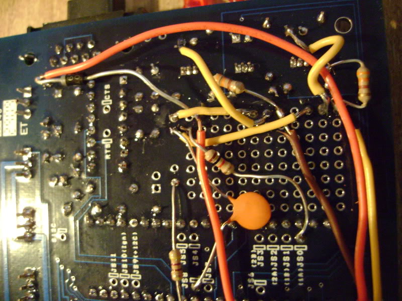
Just tore it apart, and everything seemed fine. Checked all the little wires and such right there for shorts, didn't see any. Pulled a few wires away from each other to see if it was a short I couldn't see, but after just trying it again, no difference. If it would help at all, I could download some pictures I took of the underside, in the LED area. It's my GF's camera, (otherwise they'd be iphone pics) so I'd have to wait a half hour or so till she could tell me where the USB cable is.
Reply
0
0
11-05-2009, 09:04 PM
#31
Upon close inspection of those joints, you'd know if something was loose so that must not be it.
I would like to see pics of your wiring harness if thats at all possible. At this point, the only thing I am unsure about is the wiring harness.
Worst case scenario A: You ship it back to me for inspection and another test.
Worst case scenario B: My gf and I take a vacation to Oregon for a weekend =P
Reply
0
0
 11-05-2009, 09:59 PM
#34
Cpt. Slow
Thread Starter
iTrader: (25)
Join Date: Oct 2005
Location: Oregon City, OR
Posts: 14,189
Total Cats: 1,135
Pin nothing. It was caught up in the electrical tape that I cut back to expose the wires, and is cut. I didn't just accidently cut it though, it has a female spade connecter on it from who knows when. I'm worried it went to one of my old bandaids (bipes?) then from there back to the ecu harness, and when I unplugged the bipes I never plugged it back into this. But the strange thing is I drove the car 35 miles after I took the 02 clamp and bipes off, with just the BEGi AFPR, so it did run fine.
Reply
0
0
11-06-2009, 12:13 AM
#35
Cpt. Slow
Thread Starter
iTrader: (25)
Join Date: Oct 2005
Location: Oregon City, OR
Posts: 14,189
Total Cats: 1,135
Does it matter that I'm running straight water with the mazda coolant sensor? It's been reading suspiciously high. Manifold (IAT) will be reading 56*, the coolant will ready 80-90ish, with just a minute or two of idling, which seems oddly high. I've seen a lot of settings in MT about idle control and their settings, wondering if that might have something to do with it, it does rev fairly easily. Anton and I did some more tests tonight over the phone, trying to get a 5v reading off the 2&3 trigger wire with my voltmeter, but I'm pretty sure you need an oscilloscope for that kind of quick on/off voltage. I should repeat those tests at a higher rpm. Wouldn't solve the difference in rpm between the dash and MT, but I wonder if I'm actually getting spark up higher, I just haven't wanted to rev it higher. Could just because it seems smoother once it's not running at 200rpm.
Reply
0
0
11-06-2009, 11:03 AM
#36
Boost Pope

iTrader: (8)
Join Date: Sep 2005
Location: Chicago. (The less-murder part.)
Posts: 33,027
Total Cats: 6,592
A 1k 1/4 or 1/8 watt resistor will be fairly small.
The outer LEDs should be OFF most of the time if you're running the new-n-improved spark output circuit and spark out = Inverted. They'll flicker / glow dimly with the engine running, and should be totally dark with the engine off.
I hate problems like this. They're so hard to find when I can't touch the car...
Reply
0
0
11-06-2009, 11:52 AM
#37
The outer LEDs should be OFF most of the time if you're running the new-n-improved spark output circuit and spark out = Inverted. They'll flicker / glow dimly with the engine running, and should be totally dark with the engine off.
I hate problems like this. They're so hard to find when I can't touch the car...
Joe, i've done this mod twice and i've gotten both LEDs lit like normal on both squirts. As long as the key is on, the lights are on...running or not.
The only thing I cant wrap my head around at this point is what is different about his car/setup. I tested this megasquirt on my car, worked fine, put it straight into the box it was shipped in and took it to the UPS store.
Reply
0
0
11-06-2009, 12:03 PM
#38
Boost Pope
iTrader: (8)
Join Date: Sep 2005
Location: Chicago. (The less-murder part.)
Posts: 33,027
Total Cats: 6,592
(thinks for a while...)

When Spark Out = Normal, then the "resting" state of the CPU pins is high. This causes Q6 / Q8 to turn on, allowing current to pass through D14 / D16 and pulling down the outputs. So a "normal" MS would have the LEDs on when not running.
When we set Spark Out = Inverted, this causes the resting state of the CPU pins to be low. In this state, Q6 / Q8 are off, no current flows through D14 / D16, and a positive voltage is applied to the bases of the two extra transistors, causing them to conduct across the C-E junction, thus pulling the outputs to ground. So in this scenario, those LEDs should be off.
What am I missing here? I ought to know how this damn thing works...
Curly: measure with a voltmeter to see if you have +5 on the two spark outputs (relative to ground) with the power on but the engine not running. If the coils (or igniter) are not connected, you'll probably see about 0.2 to 0.3 volts here, which is the VF (or more precisely, VCE sat) of the transistors.
As you crank the engine, you should see blips of +5 on the outputs. Probably too fast to get a solid reading with a voltmeter, but you should at least see something. Try it with the coils not connected, so you get as accurate a read as possible.
Last edited by Joe Perez; 11-06-2009 at 12:14 PM.
Reply
0
0
11-06-2009, 12:16 PM
#39
Hmm.
(thinks for a while...)
When Spark Out = Normal, then the "resting" state of the CPU pins is high. This causes Q6 / Q8 to turn on, allowing current to pass through D14 / D16 and pulling down the outputs. So a "normal" MS would have the LEDs on when not running.
When we set Spark Out = Inverted, this causes the resting state of the CPU pins to be low. In this state, Q6 / Q8 are off, no current flows through D14 / D16, and a positive voltage is applied to the bases of the two extra transistors, causing them to conduct across the C-E junction, thus pulling the outputs to ground. So in this scenario, those LEDs should be off.
What am I missing here? I ought to know how this damn thing works...
Curly: measure with a voltmeter to see if you have +5 on the two spark outputs (relative to ground) with the power on but the engine not running. If the coils (or igniter) are not connected, you'll probably see about 0.2 to 0.3 volts here, which is the VF (or more precisely, VCE sat) of the transistors.
As you crank the engine, you should see blips of +5 on the outputs. Probably too fast to get a solid reading with a voltmeter, but you should at least see something. Try it with the coils not connected, so you get as accurate a read as possible.
I've looked it over and over again for a mistake and dont see one.
Also, we tried hooking his DMM up while cranking and he barely got any voltage reading at all on either pin but from what I remember the little bit he got seemed consistent between the two spark output pins. Its just too fast for a DMM to get a reading.
Reply
0
0
11-06-2009, 12:17 PM
#40
Boost Czar
iTrader: (62)
Join Date: May 2005
Location: Chantilly, VA
Posts: 79,493
Total Cats: 4,080
pretty sure the LEDs stay lit fully regardless of rpm with joes mod with power on.
looks like one of the 330 resistors might be touching the solder joint next to it, off the yellow wire (on the right most).
looks like one of the 330 resistors might be touching the solder joint next to it, off the yellow wire (on the right most).
Reply
0
0


