vvt in na chassis sanity check with MS3x
 04-19-2013, 12:12 PM
#21
Senior Member
Thread Starter
iTrader: (6)

Join Date: Aug 2009
Location: Charlotte, NC
Posts: 924
Total Cats: 16
Oscar, it does not. He is saying to use the wires since they run back to the ecu. I took some pics of what I have today, I will upload them here when I get on a computer, cause I have a few things that I'm not sure what they are.
Hustler, do realize that I have an entire engine harness with this engine, i would rather use the connector that is already sitting there hooked up to the vvt actuator. That being said I may deloom the canister wires and hook them up to what already exists.
Hustler, do realize that I have an entire engine harness with this engine, i would rather use the connector that is already sitting there hooked up to the vvt actuator. That being said I may deloom the canister wires and hook them up to what already exists.

Reply
 0
0

0
04-19-2013, 11:35 PM
#22
Senior Member
Thread Starter
iTrader: (6)
Join Date: Aug 2009
Location: Charlotte, NC
Posts: 924
Total Cats: 16
Alright, so just a few questions about what I have here.
First pic is on the back of the head, I was wondering what this black box is with the two wires connected to it.
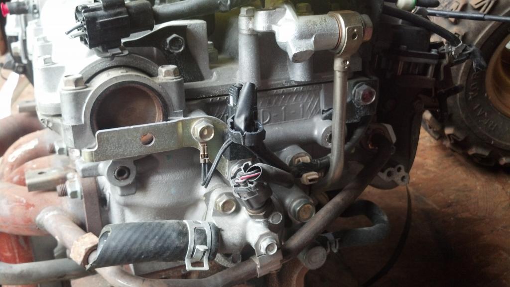
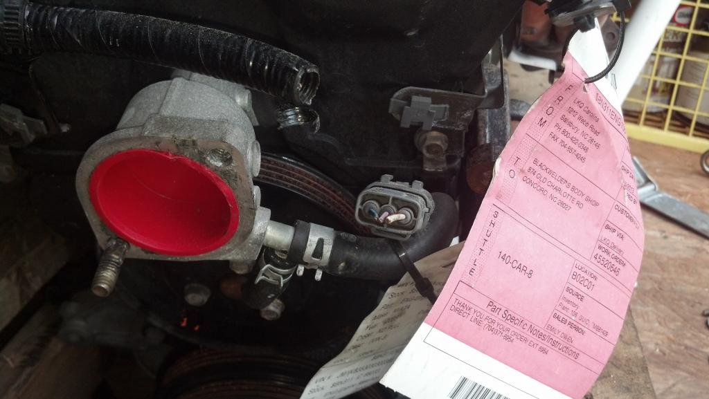
Secondly is this connector, I realize that it goes to the crank sensor, and that isnt the issue, but there are a few other wires inside this loom. Unfortunately the picture I took inside the loom came out blurry. Does anyone have any idea what all of these wires would be? Im assuming two of them are air intake temp, but the rest im not sure of.
First pic is on the back of the head, I was wondering what this black box is with the two wires connected to it.
Secondly is this connector, I realize that it goes to the crank sensor, and that isnt the issue, but there are a few other wires inside this loom. Unfortunately the picture I took inside the loom came out blurry. Does anyone have any idea what all of these wires would be? Im assuming two of them are air intake temp, but the rest im not sure of.
Reply
0
0
04-23-2013, 12:53 AM
#23
Senior Member
Thread Starter
iTrader: (6)
Join Date: Aug 2009
Location: Charlotte, NC
Posts: 924
Total Cats: 16
Bump!
MMkay, Shuiend is sending me his jimstim to borrow and verify that the MS will properly read both the cam and crank signals.
In the meantime, I have dissected what I had of the wiring harness, and made an excel sheet of the wiring colors on the vvt side, as well as what the chassis wiring harness colors should be according to wiring diagrams. I will verify the chassis wiring sometime hopefully this weekend. I have also put some thoughts and questions on the wiring or the parts that I am unsure of.
Most of my questions pertain to some of the grounds, as well as polarity. In particular, according to MS wiring on msextra, they want the coolant temp sensor grounded at a sensor ground, such as the one internal to the MS. but the current setup is grounded to one of the white connectors strapped to the chassis. Are there any problems running the grounds just as they are currently?
Regarding the idle control and VVT, correct me if I am wrong, but they are both 12v for one pin, and pwm controlled through the ecu. Does the polarity matter for either of these?
vtcs. is it worth wiring? if so, how? and how does one control it?
I also wanted to verify that the back coil (1 & 4 ) should be wired to spark A on expander board, as the front coil (2 & 3) should be wired to spark B on the expander board, correct??
https://docs.google.com/file/d/0BycN...it?usp=sharing
 for your thoughts?
EDIT: connector refers to the ground strap on the back of the head, referring to coil a and b.
and I still am not sure what the black box in picture 1 above is, or what it is supposed to do.
MMkay, Shuiend is sending me his jimstim to borrow and verify that the MS will properly read both the cam and crank signals.
In the meantime, I have dissected what I had of the wiring harness, and made an excel sheet of the wiring colors on the vvt side, as well as what the chassis wiring harness colors should be according to wiring diagrams. I will verify the chassis wiring sometime hopefully this weekend. I have also put some thoughts and questions on the wiring or the parts that I am unsure of.
Most of my questions pertain to some of the grounds, as well as polarity. In particular, according to MS wiring on msextra, they want the coolant temp sensor grounded at a sensor ground, such as the one internal to the MS. but the current setup is grounded to one of the white connectors strapped to the chassis. Are there any problems running the grounds just as they are currently?
Regarding the idle control and VVT, correct me if I am wrong, but they are both 12v for one pin, and pwm controlled through the ecu. Does the polarity matter for either of these?
vtcs. is it worth wiring? if so, how? and how does one control it?
I also wanted to verify that the back coil (1 & 4 ) should be wired to spark A on expander board, as the front coil (2 & 3) should be wired to spark B on the expander board, correct??
https://docs.google.com/file/d/0BycN...it?usp=sharing
for your thoughts?EDIT: connector refers to the ground strap on the back of the head, referring to coil a and b.
and I still am not sure what the black box in picture 1 above is, or what it is supposed to do.
Reply
0
0

 04-23-2013, 08:41 AM
#25
Boost Czar


iTrader: (62)
Join Date: May 2005
Location: Chantilly, VA
Posts: 79,494
Total Cats: 4,080
Most of my questions pertain to some of the grounds, as well as polarity. In particular, according to MS wiring on msextra, they want the coolant temp sensor grounded at a sensor ground, such as the one internal to the MS. but the current setup is grounded to one of the white connectors strapped to the chassis. Are there any problems running the grounds just as they are currently?
Regarding the idle control and VVT, correct me if I am wrong, but they are both 12v for one pin, and pwm controlled through the ecu. Does the polarity matter for either of these?
vtcs. is it worth wiring? if so, how? and how does one control it?
I also wanted to verify that the back coil (1 & 4 ) should be wired to spark A on expander board, as the front coil (2 & 3) should be wired to spark B on the expander board, correct??
These first 6 diagrams might be useful for you: Diagrams
and I still am not sure what the black box in picture 1 above is, or what it is supposed to do.
Reply
0
0
04-23-2013, 09:04 AM
#26
Senior Member
Thread Starter
iTrader: (6)
Join Date: Aug 2009
Location: Charlotte, NC
Posts: 924
Total Cats: 16
You should connect all the B/LG wires to pins 1 and 2 of the mainboard. The rest go to the solid black wires: you'll want at least two grounds off the expander and two off the mainboard on pins 7-19 to go back to the chasis grounds.
Just to verify, even though msextra runs the tps, coolant, ait grounds to pin 7, I should run them to pin 1 and 2 instead?I should be set for the grounds on the expander and the mainboard, I believe I have all 5 grounds on the expander, and 14-19 grounded on the mainboard currently, I will be verifying this this weekend.
polarity does not matter, you should wire the VVT for power off the white/red wire instead the engine bay, then only send the PWM ground back to the MS. If you're using the expander, make sure your idle, boost and VVT outputs all have beefier flyback diodes to 12v.
This was the plan for vvt, I just wanted to make sure that the polarity did not matter. What needs to happen with these flyback diodes? I know what a diode is, but im not sure what size I would need, or where the diode needs to be flying back to, or which direction it needs to be wired.
It's absoultely the worst. Get a different IM all together, the VTCS IM is the worst out there, I'd rather graft a 1.6L IM onto my block.
I plan to once funds allow, at this point im just trying to get the car up and running with this engine, I will worry about the intake later. I will just leave it unwired then.
Correct, spark A is coil pack 1&4. BR/Y.
These first 6 diagrams might be useful for you: Diagrams
Awesome, I have been using those to verify everything.
nothing. you have one already by your passenger shock mount.
Can I use the one on the back of the head instead of the one by the ignitor?
Reply
0
0
04-23-2013, 09:11 AM
#27
Boost Czar
iTrader: (62)
Join Date: May 2005
Location: Chantilly, VA
Posts: 79,494
Total Cats: 4,080
Just to verify, even though msextra runs the tps, coolant, ait grounds to pin 7, I should run them to pin 1 and 2 instead?I should be set for the grounds on the expander and the mainboard, I believe I have all 5 grounds on the expander, and 14-19 grounded on the mainboard currently, I will be verifying this this weekend.
On top of that, all the sensor grounds touch the chasis before the ECU anyways.
This was the plan for vvt, I just wanted to make sure that the polarity did not matter. What needs to happen with these flyback diodes? I know what a diode is, but im not sure what size I would need, or where the diode needs to be flying back to, or which direction it needs to be wired.
Can I use the one on the back of the head instead of the one by the ignitor?
Reply
0
0
04-23-2013, 10:33 AM
#28
Senior Member
Thread Starter
iTrader: (6)
Join Date: Aug 2009
Location: Charlotte, NC
Posts: 924
Total Cats: 16
Ok, I can handle the grounds just fine, now that I understand why everything was conflicting on where to ground.
So i need one 1n444 diode for each (vvt, idle, etc etc for everything output that i use on the expander.) I'm assuming the easiest way to do that is to run the diode externally? Connecting it to the 12v wire on the db37? (diode allowing current to flow towards 12v?)
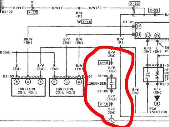
Is the condenser of such little concern that I should rid of it entirely?
So i need one 1n444 diode for each (vvt, idle, etc etc for everything output that i use on the expander.) I'm assuming the easiest way to do that is to run the diode externally? Connecting it to the 12v wire on the db37? (diode allowing current to flow towards 12v?)
Is the condenser of such little concern that I should rid of it entirely?
Reply
0
0
04-23-2013, 10:37 AM
#29
Boost Czar
iTrader: (62)
Join Date: May 2005
Location: Chantilly, VA
Posts: 79,494
Total Cats: 4,080
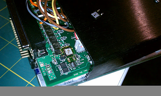
I put three in the proto and attach them to 12v and run jumper wires to the expander board at each output.
it's annoying to have to do anything of the sorts, but the circuits populated on the expander, without going through revision are not robust enough to handle the PWM they drive. When people first started running VVT on them, the drivers would overheat so much, they literally heat up the solder so much, they fall off the baord. And as is you have a horrible functional range without the extra flyback, like your idle valve would run between 60-80%DC, where when you add the extra flyback diode, you get a funcation range of 20-60%DC.
Reply
0
0
05-01-2013, 06:54 PM
#31
Senior Member

Join Date: Nov 2007
Location: Belgium
Posts: 999
Total Cats: 73
It just struck me that I got a negative prop for my post #2. Not that I care about props really, but I'm not looking for a negative prop count either. So thank you, I'll think twice in the future about offering advice  .
.
.
Reply
0
0
 05-02-2013, 02:11 PM
#33
Senior Member
Thread Starter
iTrader: (6)
Join Date: Aug 2009
Location: Charlotte, NC
Posts: 924
Total Cats: 16
Also, I am getting ready to build what is needed for this harness. and just to make sure, I am using the vvt output and the tach output on the expander. idle will be run on the main board. does that mean I need one flyback for vvt, or do I need a flyback to drive the tach as well?
Reply
0
0
05-03-2013, 11:25 AM
#35
2 Props,3 Dildos,& 1 Cat

iTrader: (8)
Join Date: Jun 2005
Location: Fake Virginia
Posts: 19,338
Total Cats: 573
A smart, safe idea is to run a flyback diode across the VVT +12 (S12) and VVT output.
TOAST:
Reply
0
0
05-05-2013, 11:20 PM
#36
Senior Member
Thread Starter
iTrader: (6)
Join Date: Aug 2009
Location: Charlotte, NC
Posts: 924
Total Cats: 16
I was originally planning to wire it into the harness, but I may just do that instead, sounds a bit easier tbh. I only plan on using the vvt output on the expander, Idle will be on the main board, and boost is n/a due to well... lack of boost for the time being.
Reply
0
0
05-10-2013, 12:24 AM
#37
Senior Member
Thread Starter
iTrader: (6)
Join Date: Aug 2009
Location: Charlotte, NC
Posts: 924
Total Cats: 16
Alright, I am missing one last component. I am missing the post thermostat waterneck on the front of the head. Yes, thats right, I am not running a coolant reroute for the time being... At this point I just want the engine in the car and running. Does anyone know engines that may be at a junkyard to pull a part off of that will work? My understanding is that the kia part faces the wrong direction and will not work.
Reply
0
0

Thread
Thread Starter
Forum
Replies
Last Post
StratoBlue1109
Miata parts for sale/trade
21
09-30-2018 01:09 PM


