
The Better Bilstein Ebay Coilover Thread
 11-29-2016, 03:41 PM
#1001

I think for the best chance of success I'm gonna pull apart my bad hard s shock and see if I can't place the exact bilstein part number for as many things as possible, but mainly the piston.
Once I've got that, I imagine Poway ought to be able to tell me what digressive shim stack I need for a certain spring rate. "valvingmanual_31to40.pdf" has a lot of the available common digressive valvings, all called things like "6020, 6010, 4555" etc.. I imagine this relates to the force needed at the knee on the digressive valving somehow. It's also common to call valving based on 10in/s but I'm not sure how much that'll tell you on a digressive valving...
Don't know though, might be nice to upgrade them all to the "COB" piston if they don't already have them. It looks like those things have much less of a shim stack to mess with.
Assuming my shock isn't already depressurised from the control arm folding in on it, what's the best way to pop them? I was just going to pilot with a small 1/8 or 3/16 drill to let all the air out. Might maybe wear glasses for once...

Reply
 0
0

0
 11-29-2016, 07:40 PM
#1003
Senior Member

Join Date: Dec 2004
Location: Brisbane, Australia
Posts: 1,278
Total Cats: 37
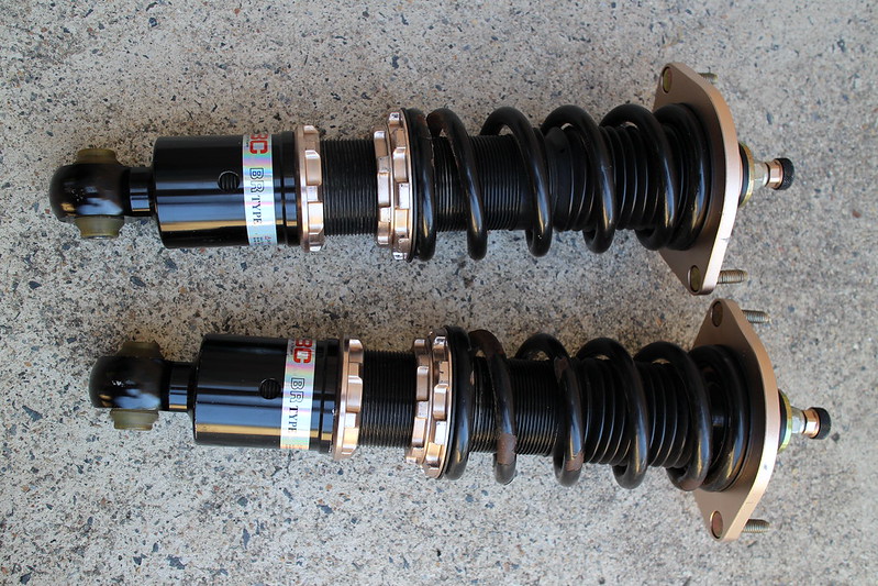
Although I'm out of the MX-5 game now, back in the day I played around a bit with BC BR shocks which use a 46mm piston so you can swap Bilstein bits into them (both valve stacks and pistons). They are really easy to pull apart yourself. The only challenge is charging the nitrogen after reassembly.
I thought this was common knowledge but I haven't seen mention of it, so I'll post some pics.
These are the shocks I'm talking about:
On the underside it has a hex head you remove to expose a self-healing seal for nitrogen vent/charge:
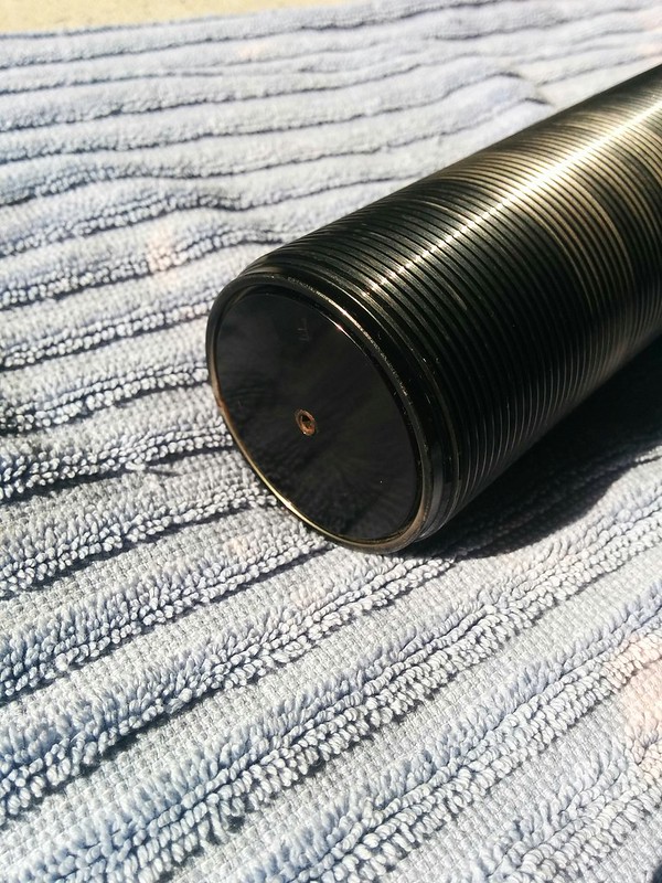
Here's a video of my venting one for the first time, I had no idea what to expect so proceeded slowly:
You can see the oil coming out at the end that had made it past the seals into the nitrogen section. You can use a Bilstein separator piston as a replacement.
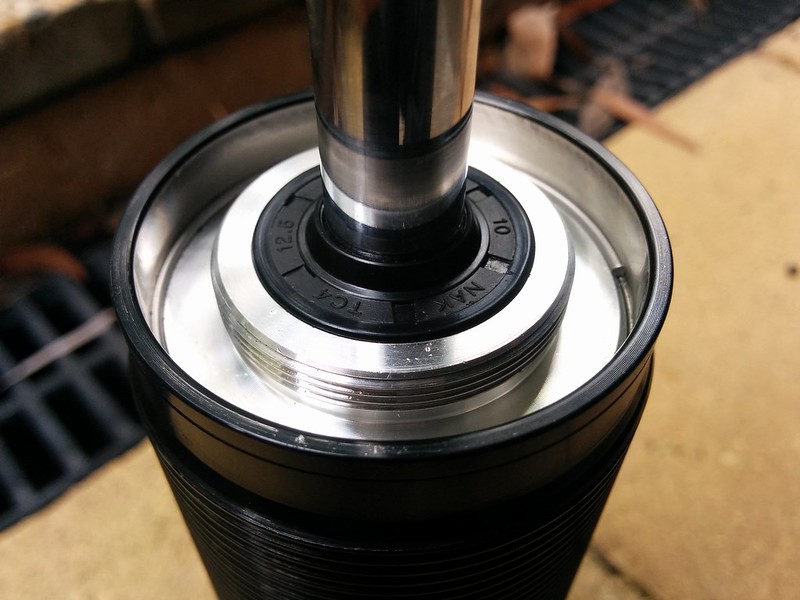
After you have vented the nitrogen, you unscrew the top plate to expose the wiper seal:
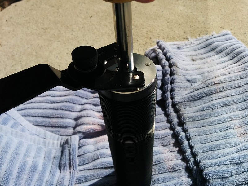
You press this down to remove the circlip:
Cheers
I thought this was common knowledge but I haven't seen mention of it, so I'll post some pics.
These are the shocks I'm talking about:
On the underside it has a hex head you remove to expose a self-healing seal for nitrogen vent/charge:
Here's a video of my venting one for the first time, I had no idea what to expect so proceeded slowly:
You can see the oil coming out at the end that had made it past the seals into the nitrogen section. You can use a Bilstein separator piston as a replacement.
After you have vented the nitrogen, you unscrew the top plate to expose the wiper seal:
You press this down to remove the circlip:
Cheers
Reply
0
0
11-29-2016, 08:24 PM
#1004
Junior Member

Join Date: Jan 2016
Location: Allen, Texas
Posts: 80
Total Cats: 3
I wonder if the BR shock bits transfer over to the Bilsteins? That would certainly be interesting!
The easy part is cracking the things open and getting a shop to refill them/using the equipment to do it yourself. The hard part is trying to figure out what shim stacks, pistons, etc. to use for what spring rate and what not. Hopefully Bilstein is willing to do the heavy lifting for us and specify which parts we need.
Like I said, I'm very interested to see where this leads. Being able to custom valve these on the cheap would definitely make these close to the best setup short of something like Xidas.
Found someone on the Honda forums who's tackled a DIY revolve. Haven't read it all yet.
Last edited by crispyBYM; 11-29-2016 at 08:46 PM.
Reply
0
0
11-29-2016, 09:22 PM
#1005
Senior Member
Join Date: Dec 2004
Location: Brisbane, Australia
Posts: 1,278
Total Cats: 37
I designed a shim stack I was going to use but it never eventuated due to time constraints. The BC BR has a piston bypass (twisting the **** on the top dictates how much the bypass is open) so you would probably valve it harder than a static setup.
I'll try to dig out some old notes if you want? Bilstein had a digressive valving guide I looked at quite a bit.
Having access to a shock dyno would be very nice.
I'll try to dig out some old notes if you want? Bilstein had a digressive valving guide I looked at quite a bit.
Having access to a shock dyno would be very nice.
Reply
0
0
11-29-2016, 10:24 PM
#1006
If I were to build a frame with a load cell and a throttle position sensor on the fulcrum how would I turn that into good f/v plots?
I understand the principle, knowing the pivot points and basically TPSdot will give you velocity, a simple load cell gives you force. I have a USB DAC, but I'm pretty sure it's output only...
I think I can get the signal from both the sensors into a PC easily enough, but what software and who can help me code it? I bet I could do it with a megasquirt and do maths on megalogviewer, but that's hackwork...
Reply
0
0
 11-29-2016, 11:13 PM
#1009
Junior Member

Join Date: Nov 2016
Posts: 48
Total Cats: 2
I could code the hell out of this for you -- I honestly don't think this would be very hard with an Arduino. One ADC for the load-cell and one ADC for the LVT (for velocity measurement). Drop a weight twice, once just to figure out the force onto the load-cell, the other to drop onto the rod of the shock to measure the velocity.
But now I'm questioning my engineering know-how (I studied stuff that doesn't move in a macroscopic scale): why are all the graphs of shock dynos in force vs velocity? You'd think force would be the input, no?
But now I'm questioning my engineering know-how (I studied stuff that doesn't move in a macroscopic scale): why are all the graphs of shock dynos in force vs velocity? You'd think force would be the input, no?
Reply
0
0

 11-29-2016, 11:50 PM
#1011
Junior Member
Join Date: Jan 2016
Location: Allen, Texas
Posts: 80
Total Cats: 3
This is what the guy on the Honda forum came up with. Post #7 goes into a bit more detail on how the fulcrum is designed. Here is how he revalved a Sport Shock.
I could also ask around my universities FSAE team. I'm sure they would be very interested in building a shock dyno, if they haven't gotten one already. The more people that can test out different setups the better.
I could also ask around my universities FSAE team. I'm sure they would be very interested in building a shock dyno, if they haven't gotten one already. The more people that can test out different setups the better.
Last edited by crispyBYM; 11-30-2016 at 12:13 AM. Reason: Detail
Reply
0
0
11-30-2016, 03:09 AM
#1013
How do you all think this would work?
A 500kg tension/compression load cell, should be good for 1,000 lbs or so.
S Type Load Cell Weighing Sensor Pressure Sensor 5kg~500kg | eBay
One of these little cheap amplifiers and an appropriate power supply, 12V is probs best. There are arduino load cell and analog/digital converters available as one board, but far as I can tell they run off 5V and I don't think that's enough for the larger load cells.
0-10V / 4-20mA Load Cell sensor Amplifier Transmitter voltage current converter | eBay
And a arduino digital to analog converter. This one is 4 channels, should be plenty?
ADS1115 Module 4-CH 16 Bit AD Module Analog to Digital Breakout for Arduino 0-5V | eBay
And the cheapest throttle position sensor you can find, or at least the one that looks the most convenient to mount. Could build a little 5v power supply, or probably just buy one on ebay for a few pennies.
So that should be well less than $100 in electronics, then all you'd need is a program that logs the two inputs and does some math to save a point. This is the part I suck at, I know you'd need to log the current force on the load cell and the rate of change on the position sensor. I don't even know where to start, guess I should buy some stupid little arduino scale or thermometer kit or something. I'll figure out the slope calculation later...
Would be super sweet if you could make a shock dyno for less than the cost of a new bilstein. I'm looking at my engine stand and it sure looks like a good and easily reversible base to work off of. I think it's possible, sure gonna give it a try.
Reply
0
0
11-30-2016, 07:45 AM
#1014
Junior Member

Join Date: Nov 2012
Location: Netherlands, Europe
Posts: 204
Total Cats: 29
I think it will be very hard to make a nice sweep across different speeds / forces in both directions.
You would have to gradually increase damping speeds while keeping your travel/stroke more or less the same.
I am also wondering if you are able to reach the full operating range of shock speeds/forces by hand.
Ideally you want to add a powerful electronic motor with the shock mounted to a crank: that way you can much more easily reproduce your measurements.
If you power it by a an electronic motor you can also bring the shock up to temperature.
And if you make multiple mounting points on the crank you can play with the speed/travel/force range you are measuring.
Reply
0
0
11-30-2016, 11:36 AM
#1015

Rather than the TPS, what about a laser rangefinder (if you are an outdoorman/hunter? lol) or IR range-finder? IR sensors are cheap (https://www.amazon.com/GP2Y0A21YK0F-...ords=ir+sensor).
Also, what about using a large arbor press as your load applier? You can add more and more force by increasing the moment arm and you already intend to estimate the velocity from the position change versus time, so...
I also agree it would be very easy to code in excel, labview, or matlab, but the reliability and precision of the methodology a bigger question.
Reply
0
0
11-30-2016, 02:19 PM
#1016
It'll be super easy to get a nice sweep across a whole range of velocities, you just simply jack it slow, or jack it fast. It will pass through most all velocities that way, An electric motor won't change that problem, not as I see it. There is no need for a smooth or repeatable stroke, in fact it's exactly what I don't want as I want to measure across all shaft speeds. If I make a motor and crank not only does my frame need to take that beating, I then need to come up with all these different mounting holes and angles so I can get different speeds out of a fixed motor and crank. That's all just needless complication in my eyes, the shock cares not if it's me pushing the lever or a crank powered by a motor. I am measuring monotube shocks, if I want to test them at temperature I'll preheat them on the pavement outside or something, I doubt I'll notice any difference I can measure as that's supposed to be one of the things monotubes are good at...
I'm not trying to do a football plot, I am going to measure a cloud of points. when they are all laid out, hopefully I have something that resembles a shock dyno.
I will look into lidar or something similar, but not an arbor press. An arbor press is at least twice as complicated as the simple fulcrum I need. I am not adding force, I intend to add velocity through a lever arm and measure the resulting force and plotting the results. It does not need to be any more complicated than this.
While I'm sure the data I get won't be the most accurate data, I think I will be able to get highly precise data. As I want to compare before and after, precision is all I really need.
Reply
0
0
11-30-2016, 03:15 PM
#1017
Junior Member
Join Date: Nov 2016
Posts: 48
Total Cats: 2
When you get your sweep of velocities, it's best to take the derivative of that (to find the acceleration), superimpose it on the velocity graph, and ignore all the data that has an acceleration not near zero. Someone should correct this statement if the math is wrong. The other issue with doing it by hand is that you may run out of displacement before you're up to speed.
I'm thinking of ghetto-rigging something with compressed air and a pneumatic piston. Using an electric motor is really tough because you'd have to machine a scotch-yoke.
This is totally hijacking this thread. We should probably start a new one.
I'm thinking of ghetto-rigging something with compressed air and a pneumatic piston. Using an electric motor is really tough because you'd have to machine a scotch-yoke.
This is totally hijacking this thread. We should probably start a new one.
Reply
0
0
11-30-2016, 05:34 PM
#1018
I agree, we should probably start another thread.
But just one more question, bilstein makes all sorts of valving kits for the old digressive piston. They are called 3030, 4040, 5050, 6060, 7060, 6010, 6065 etc... They are super simple, just four shims. You can even buy a kit that supposedly has two sets of eight most popular valvings.
They also call out some linear valving, those are super easy to understand. For example a 180/120 is 180lbs at 10ips rebound and 120lbs at 10ips compression.
The COB stuff is even further wacky, as far as I can tell it's just a digressive piston with a check valve to make for even sharper knee in one direction only. I think besides the check valve everything else shares the old digressive 4 shim stack. Bilstein has chosen to name these valvings something else that seems to be closer to the single digit circle track stuff. I don't understand this at all, yet.
I can't find any way to make any sense of the digressive valving naming, and I'm coming up empty on searches. I have read many bilstein pdfs, besides calling bilstein I think I might need to hit a circle track forum or something...
Last edited by deezums; 11-30-2016 at 05:44 PM.
Reply
0
0
12-01-2016, 09:50 AM
#1019
Junior Member
Join Date: Jan 2016
Location: Allen, Texas
Posts: 80
Total Cats: 3
Anyone have an idea of how to properly match the valving for a spring rate though? I've heard of aiming for around 70% critical damping. There has to be some formula out there.
Reply
0
0
12-01-2016, 09:58 AM
#1020
Junior Member

Join Date: Jun 2016
Location: Dousman, WI
Posts: 147
Total Cats: 14
Lots of ways to skin the "DIY shock dyno" cat; I'm doing compressed air. The commercial shock dynos use cranks which are clever in that you can use nice cheap quadrature sensors for position measurement instead of expensive linear pots. Moving the shock in a sine wave sorta thing is nice because it gets you a range of velocities in one stroke, but other motion styles can be good for looking at different things.
I am proud of my homemade shock dyno - Corner-Carvers Forums Funny that it popped up on another forum I'm following about the same time. I'm the non-OP doing this stuff in that thread.
Like was said, maybe this needs a new thread.
*edit*
http://www.worksevo.com/Damper_Curves_2.pdf This is a decent thing as it explains some of the reasoning. But if you look at critical damping of real, good performing shocks, you'll notice that it diverges a lot in places - plotting critical damping percentage vs shock velocity shows you some really interesting stuff. The "whys" there gets to be the secret sauce of all of this stuff.
I am proud of my homemade shock dyno - Corner-Carvers Forums Funny that it popped up on another forum I'm following about the same time. I'm the non-OP doing this stuff in that thread.
Like was said, maybe this needs a new thread.
*edit*
Reply
0
0


