

Aerodynamic Discussion Thread


Like Blackbird said, EP cars have been doing similar setups for a while... but since you asked, here is the original thread from when I did mine back in 2011, it was the first non-EP Miata with one that I know of: https://www.miataturbo.net/race-prep...ducting-60291/

Reply
 0
0

0

Just use 4 bolts under the hood for the bumper, and cut the point out where it bolts to the fender and replace it with a quick latch like thing. Something like these but smaller theres plenty of options.
Pictures:
Reply
0
0

Thread Starter
Senior Member
Joined: Oct 2011
Posts: 646
Total Cats: 62
From: The Race Track & St Pete FL
I used 4 dzus fasteners along the top edge and then one on each corner with these brackets attached to the fender. Has held up that way for 2 seasons but it's just the bumper skin.
Pictures:
Pictures:
AMS Evo X Hood Radiator Vent


Reply
0
0
Thread Starter
Senior Member
Joined: Oct 2011
Posts: 646
Total Cats: 62
From: The Race Track & St Pete FL


Reply
0
0
Thread Starter
Senior Member
Joined: Oct 2011
Posts: 646
Total Cats: 62
From: The Race Track & St Pete FL
I think it was in the book Maximum Boost that talked about when making a duct to go to the radiator or intercooler has to be 20%-30% smaller than the surface area of the heat exchanger. I guess it is to draw the air in, instead of force it in with drag on the car.
Reply
0
0

Elite Member
Joined: Apr 2010
Posts: 2,826
Total Cats: 66
From: Newcastle, Australia
Finally took this out,
Monster grip, very very stable.
Happy days.
Turbo setup held up good also.
In, passed scrutineering no hastles, drop the tyre pressures on the slicks, check, double check, triple check.
Out for qualifying, first lap out, first time down the straight the splitter failed.
I tested it to about 150kg jumping on it so I was amazed, when he came in a quick check showed that it generated so much downforce it tore chunks of steel out of the bodywork!

Here is a piece I retrieved from the other side.
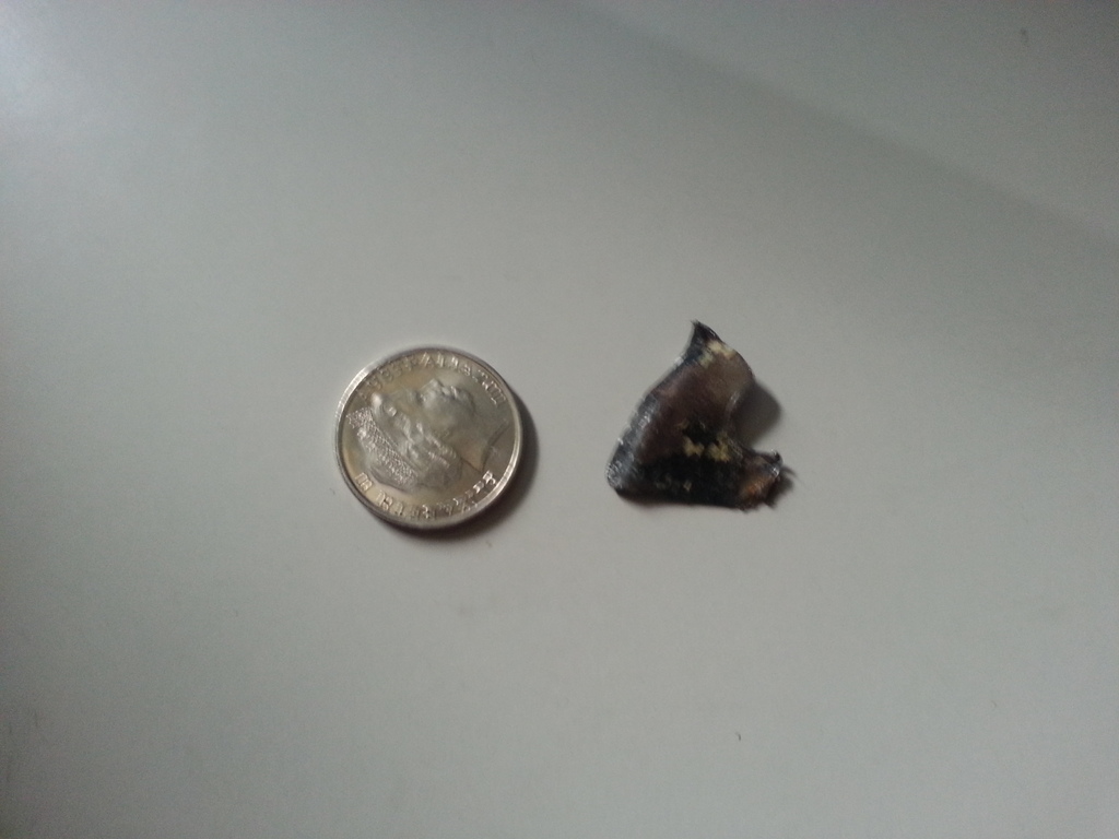
Its held on with 6 bolts and only the front 2 had issues, so lesson learned, the splitter is way way more efficient than Id even hoped so it was remounted with a temporary but strong solution. So great news about the front aero design, also looks like the cooling issues the car has always had have been solved with these recent changes.
Here is the excel series and the pulsar series in together.
And a few pics from the field.


Dann
Monster grip, very very stable.
Happy days.
Turbo setup held up good also.
In, passed scrutineering no hastles, drop the tyre pressures on the slicks, check, double check, triple check.
Out for qualifying, first lap out, first time down the straight the splitter failed.
I tested it to about 150kg jumping on it so I was amazed, when he came in a quick check showed that it generated so much downforce it tore chunks of steel out of the bodywork!
Here is a piece I retrieved from the other side.
Its held on with 6 bolts and only the front 2 had issues, so lesson learned, the splitter is way way more efficient than Id even hoped so it was remounted with a temporary but strong solution. So great news about the front aero design, also looks like the cooling issues the car has always had have been solved with these recent changes.
Here is the excel series and the pulsar series in together.
And a few pics from the field.
Dann
Reply
0
0
Thread Starter
Senior Member
Joined: Oct 2011
Posts: 646
Total Cats: 62
From: The Race Track & St Pete FL
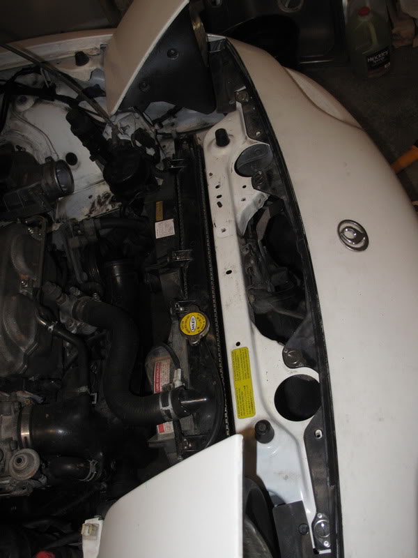
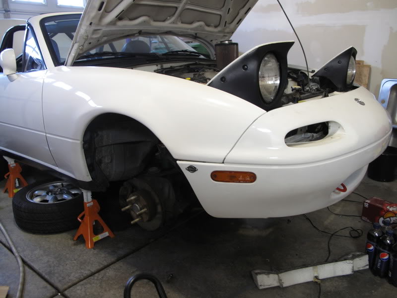
OK so a triple post but that is a good looking track Miata. I mounted my splitter to a steel structure that bolts to the factory bumper bulges (bumper bulges been removed)
Reply
0
0
Elite Member
Joined: Apr 2010
Posts: 2,826
Total Cats: 66
From: Newcastle, Australia
**** me, can someone please fix the TP.
I didnt realise, I was having trouble with firefox, using chrome now, swore I never would.
Thankyou mate, this was remounted using the factory weld nuts you can see in the first photo.
Thanks
Dann
I didnt realise, I was having trouble with firefox, using chrome now, swore I never would.
Thankyou mate, this was remounted using the factory weld nuts you can see in the first photo.
Thanks
Dann
Reply
0
0
Elite Member
Joined: Apr 2010
Posts: 2,826
Total Cats: 66
From: Newcastle, Australia
Also the hole has to be smaller than the surface area of a cooler because if the coollers frontal area is 50% metal, 50% air holes then it will only flow 50% of its area wont it.
Dann
Dann
Reply
0
0
Elite Member
Joined: Apr 2010
Posts: 2,826
Total Cats: 66
From: Newcastle, Australia
No it doesnt need to be smaller but thats why it can be, My apologies.
Im fairly certain making it larger doesnt do anything because there isnt more pressure just a boundary layer.
Dann
Im fairly certain making it larger doesnt do anything because there isnt more pressure just a boundary layer.
Dann
Reply
0
0
Like Blackbird said, EP cars have been doing similar setups for a while... but since you asked, here is the original thread from when I did mine back in 2011, it was the first non-EP Miata with one that I know of: https://www.miataturbo.net/race-prep...ducting-60291/

Reply
0
0


Junior Member
Joined: Jun 2011
Posts: 409
Total Cats: 20
From: Houston
Awesome 
Regarding the heat exchanger intake area: The reason you want the intake area to be about 1/3 of the frontal area of the heat exchanger is due to bernulli's principle. The efficiency of a heat exchanger is affected by the pressure differential across it. Bernulli says that when velocity decreases pressure increases. So if we have a small opening with ducting that opens up behind it, the velocity will decrease as the cross sectional area of the ducting increases and it will create a higher pressure in front of the heat exchanger.
Regarding your torn out splitter mounting points: why not use those nice reinforced threaded holes just above the holes you used? Thats what I've used to support my similarly sized splitter for years without any problems.
Reply
0
0


