Barton's na6
 04-03-2020, 03:07 AM
#61
Junior Member
Thread Starter

Join Date: Jun 2015
Location: VIC, Australia
Posts: 182
Total Cats: 58
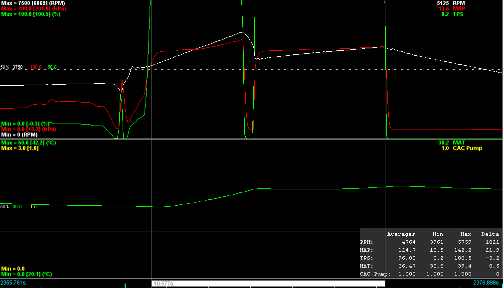
Visited Winton raceway a few weeks ago. Nut behind the wheel was very rusty and only managed a 1:40.86 even with the wider wheels and RS-4 tyres. 0.1 off my PB with no turbo and 205 RE71Rs. I did however get some good data.
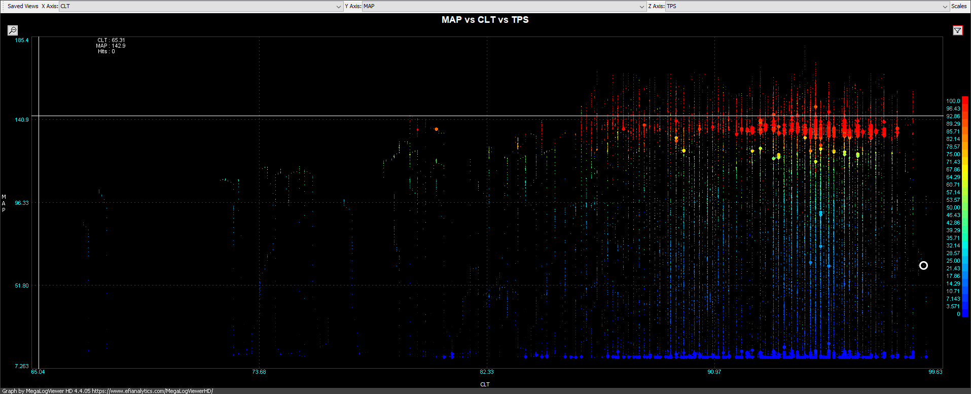
Engine coolant temperatures with the new electric water pump peaked at a slightly higher temperature than previously (~100degC) although that is likely due to the water to air heat exchanger sitting in front of the radiator. Nothing to worry about at this point.
Engine coolant vs MAP
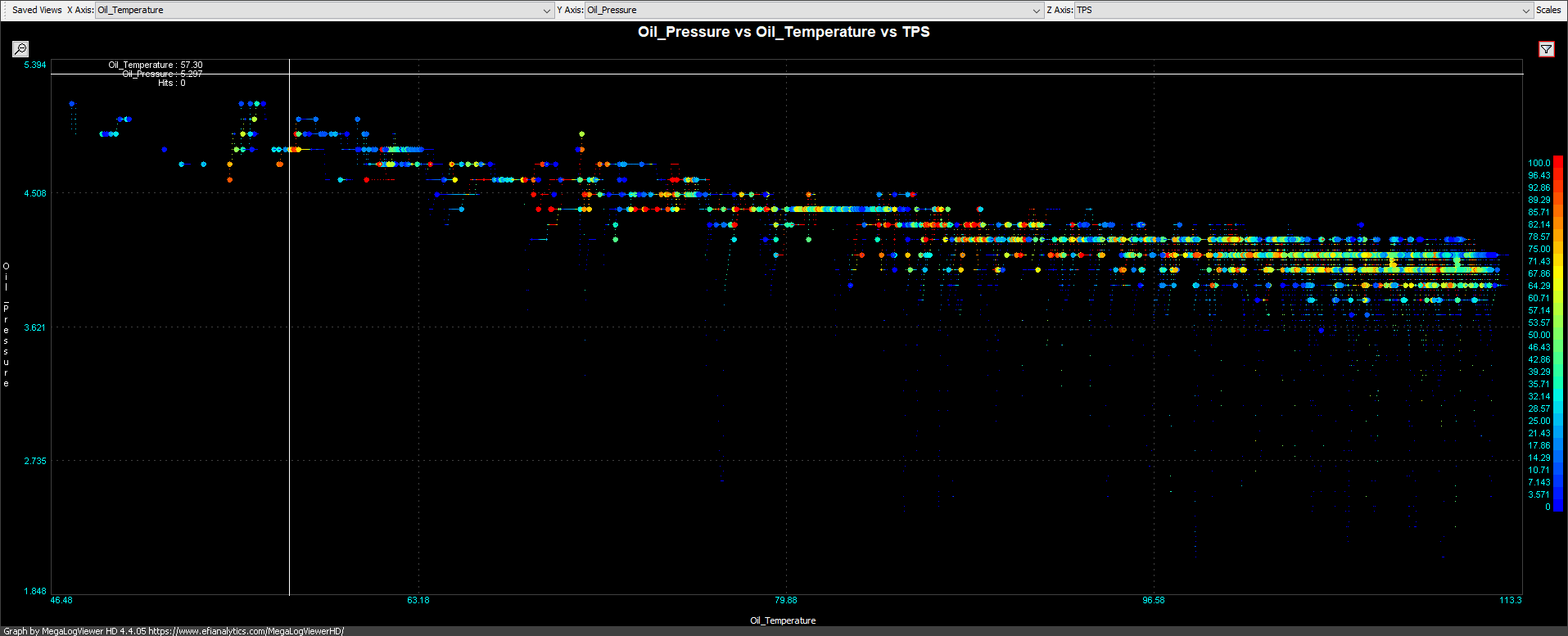
Oil temperature was quite good reaching a peak of 110degC without the use of an oil cooler. I previously removed the oil cooler since temperatures on the street were too cold. When fitting the electric water pump I reversed the flow through the 'warmer' under the oil filter so that cool water straight from the radiator would flow though it instead of hot water from the rear of the head. I'm not sure how much this would help but oil temperatures look pretty good.
Oil temperature vs oil pressure
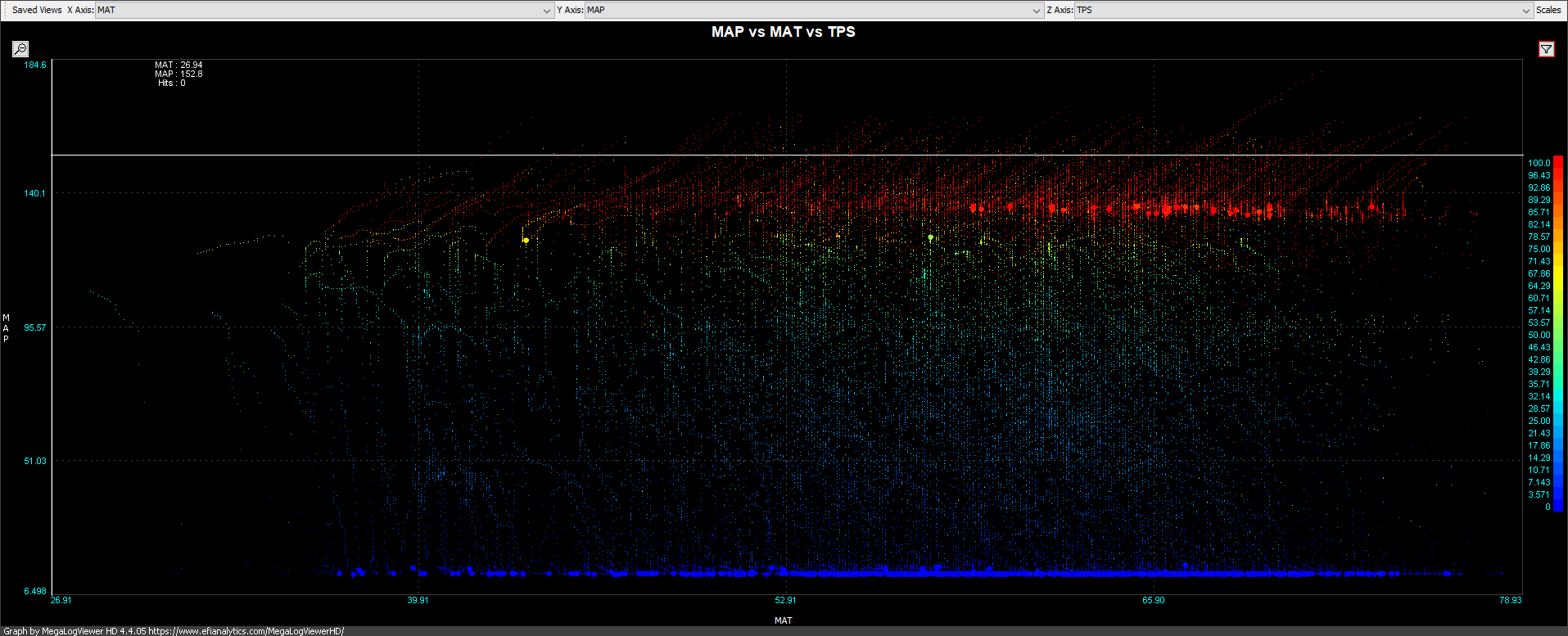
The charge air cooler did not work very well which I was expecting. Definitely need to change the heat exchanger to something more suited to the job. The temperature stabilised around 70degC which is far too hot.
Intake air temperature vs MAP
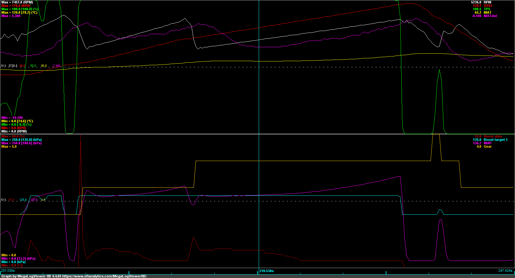
I also did notice that I was getting boost creep from 6000rpm on so the turbo wastegate could benefit from some porting to improve flow.
Engine coolant temperatures with the new electric water pump peaked at a slightly higher temperature than previously (~100degC) although that is likely due to the water to air heat exchanger sitting in front of the radiator. Nothing to worry about at this point.
Engine coolant vs MAP
Oil temperature was quite good reaching a peak of 110degC without the use of an oil cooler. I previously removed the oil cooler since temperatures on the street were too cold. When fitting the electric water pump I reversed the flow through the 'warmer' under the oil filter so that cool water straight from the radiator would flow though it instead of hot water from the rear of the head. I'm not sure how much this would help but oil temperatures look pretty good.
Oil temperature vs oil pressure
The charge air cooler did not work very well which I was expecting. Definitely need to change the heat exchanger to something more suited to the job. The temperature stabilised around 70degC which is far too hot.
Intake air temperature vs MAP
I also did notice that I was getting boost creep from 6000rpm on so the turbo wastegate could benefit from some porting to improve flow.

Reply
 0
0

0
01-11-2021, 05:05 PM
#62
Junior Member
Thread Starter
Join Date: Jun 2015
Location: VIC, Australia
Posts: 182
Total Cats: 58
Haven't updated this in a while but not a lot has happened in 2020 with lockdowns here.
Received and fitted a Honed Developments brake booster delete. Very well put together kit that was quite easy to install. It comes with a new push-rod for the master cylinder and a template to drill a new mounting hole in the brake pedal to move the pivot point. The pedal feels a bit stiffer but I quickly got used it it. It feels much easier to control brake pressure now and the pedal feels much more linear.
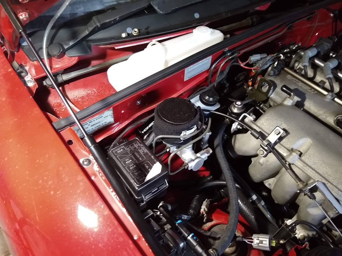
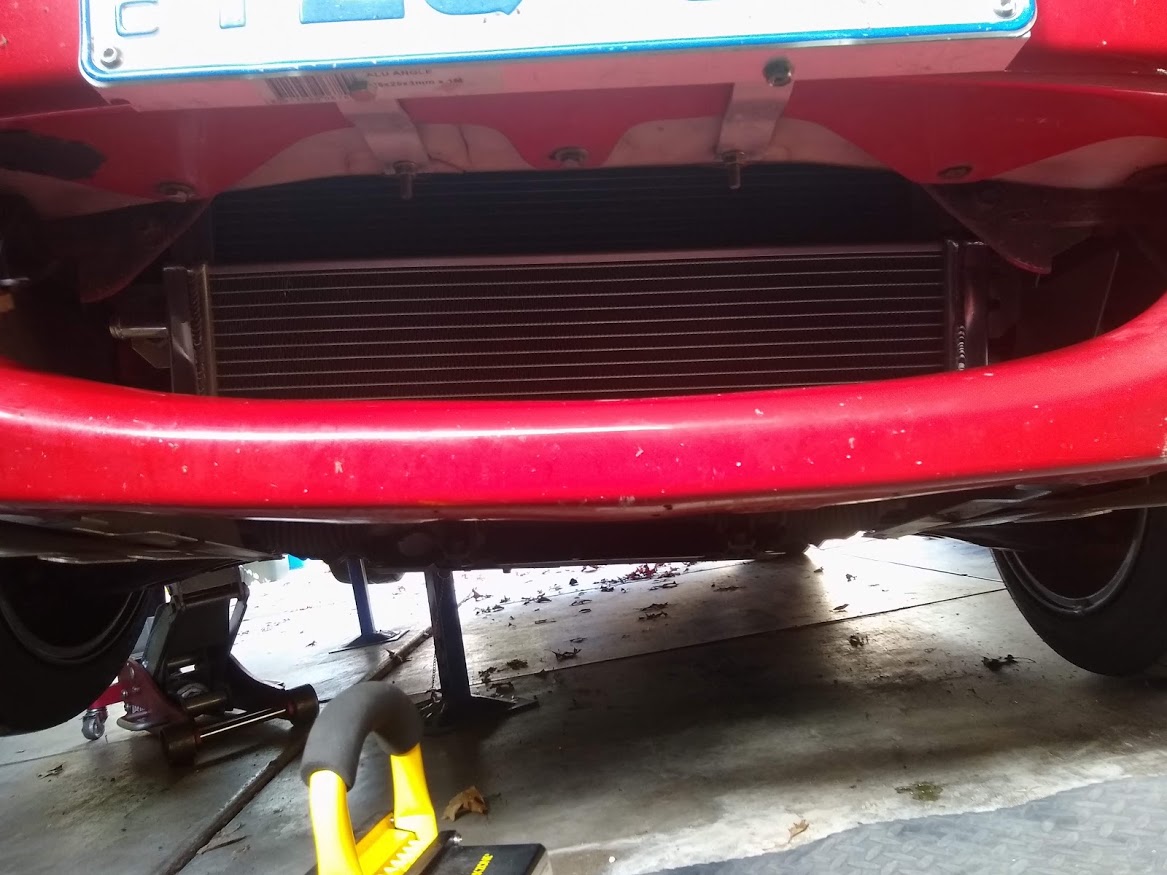
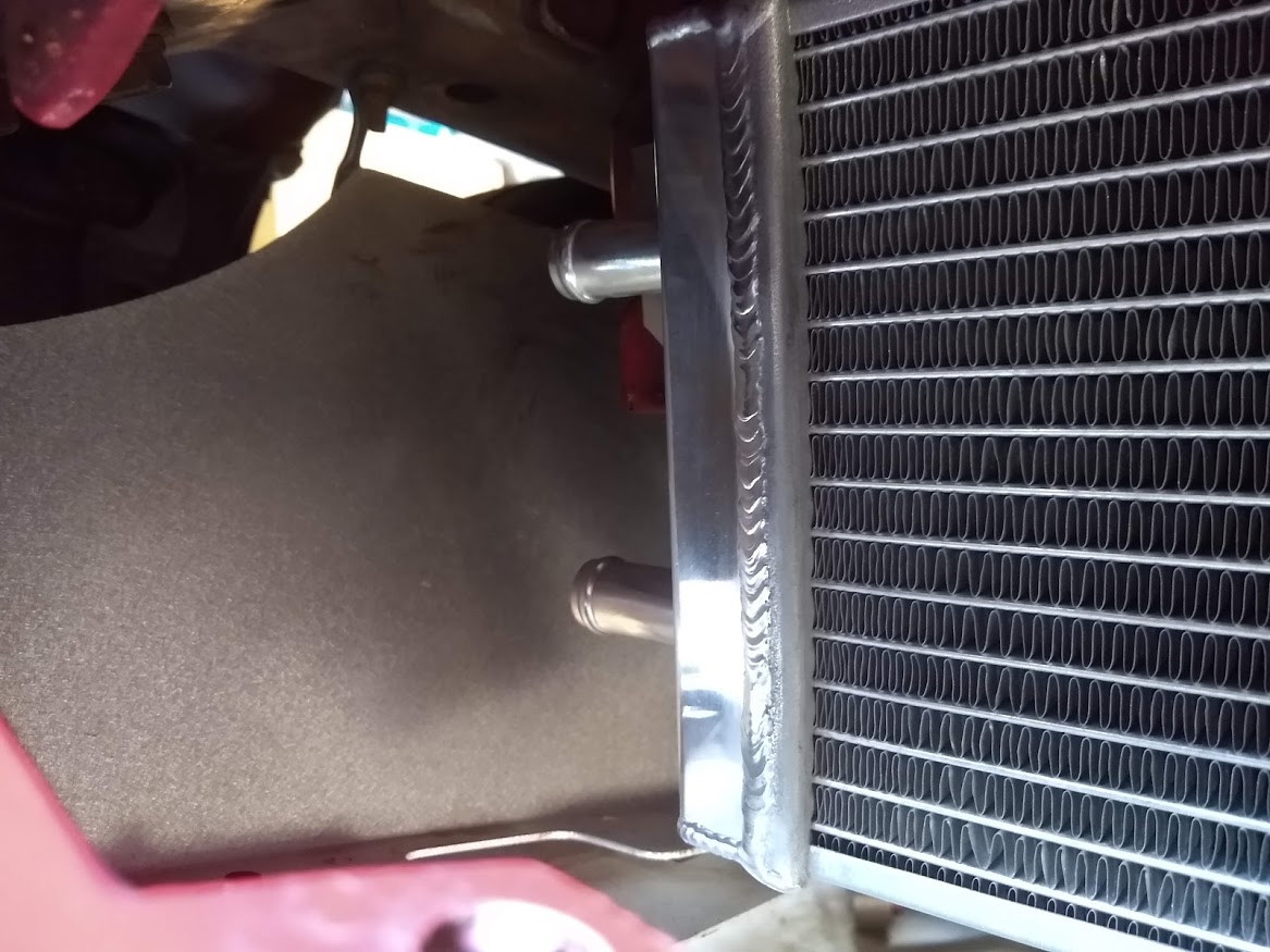
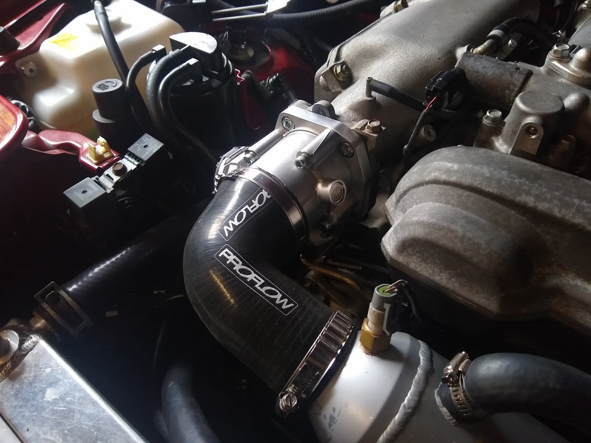
I also fitted a new heat exchanger for the inter-cooler which bolted right up to the A/C condenser brackets. It should be much more effective than the A/C condenser however both barbs are on the same end-tank and I don't believe there is any internal baffling to split the end-tank to make it a true dual core radiator. If I run the pump to circulate coolant through it the air temperature rises fairly quickly on boost however if I leave the pump off so that the water in the radiator cools and then turn the pump on in boost the temperature stays quite stable for a while. Plan is to cap one of the barbs off and add a new one on the other side so that the water will flow properly through the core. I guess I should expect this sort of thing from eBay parts
I then capped one of the barbs off and then drilled/tapped and added a new fitting to the other side to allow the water to flow across the core properly.
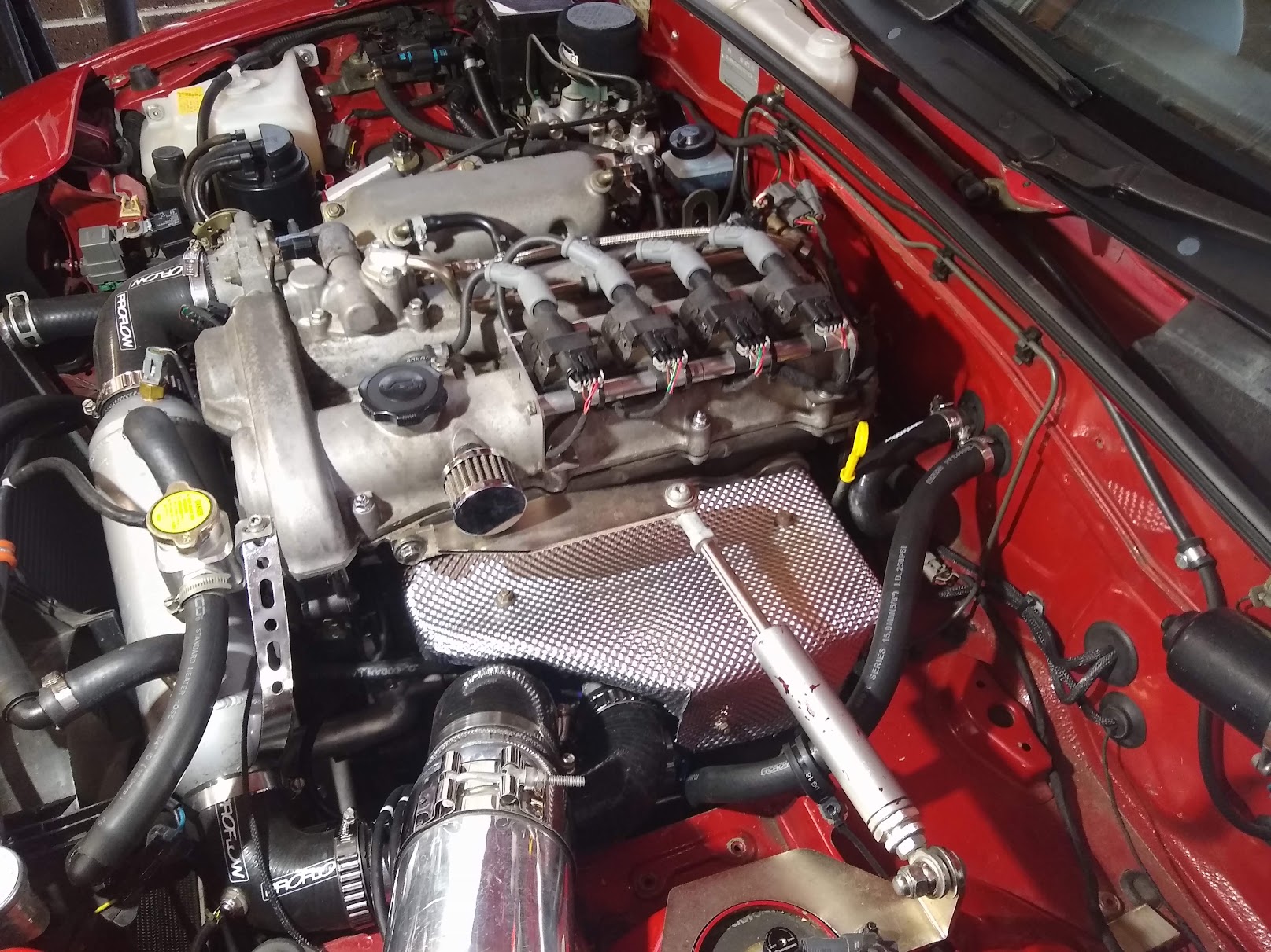
I've also moved to a new low mount Kraken manifold as I preferred the design over the high mount version. I needed to make a new longer oil feed line, change the oil drain for a shorter one (was sent a long one by mistake originally but it worked out anyway). Also had to clock the turbo bearing housing to get the drain on the bottom as well as the compressor outlet to point down again.
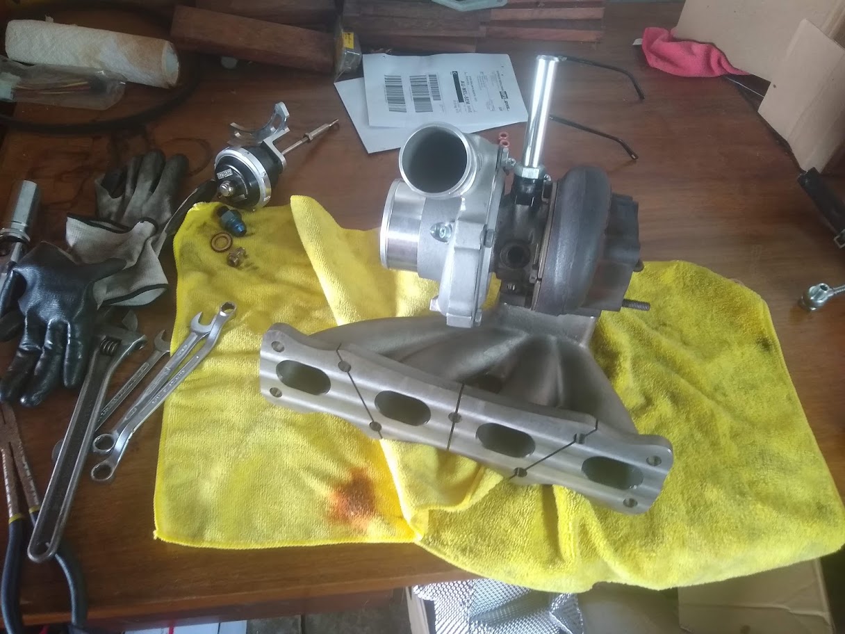
Due to the position of the turbo now the compressor inlet has interference with the water pump inlet housing. Luckily since I had already modified it to delete the heater return pipe it was an easy job flipping it the other way around to get it out of the way.
I decided to keep the oil feed on source from the VVT actuator since it was easier to just leave it there than run it down to the oil pressure sensor port which was my original plan.
Unfortunately I didn't have the right silicone bends to have the compressor outlet facing down. Limited room down there since the subframe and water pump is quite close and there' a limited angle the compressor can be clocked to due to the wastegate actuator. For now I've just got it pointed out the side.
Accessing all the bolts and fittings is so much more difficult than the 'high' mount version of the manifold. Luckily there was still half decent access to the dump pipe bolts and oil feed fitting to tighten them but the water and drain fittings had to be tightened to the manifold before it was lowered in. I'll look into different fittings to connect the water lines since it's not ideal having to take the manifold off to loosen or tighten them.
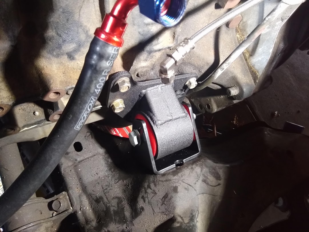
Also while everything was off and I had good access I swapped the engine mount for an innovative poly one. Annoyingly it didn't clear the dipstick tube so I had to grind it down for clearance. Not sure Why that would be the case.
Went to take it for a test drive the other day and fill the tank up since the fuel that was in there was quite old. Ended up stalling when I got back home and wouldn't restart. Checked the data and it went lean for no apparent reason. Waited about 30min and restarted and left it idling and stalled again after about 10min. Unfortunately I haven't got a fuel pressure sensor but from what I could tell it was losing pressure. Had a look at the fuel pump relay and the fuse and contact in the relay had melted a bit. Looked like it was getting too hot.
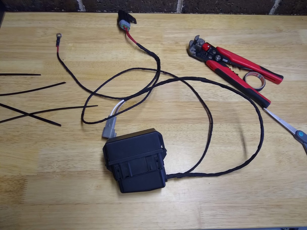
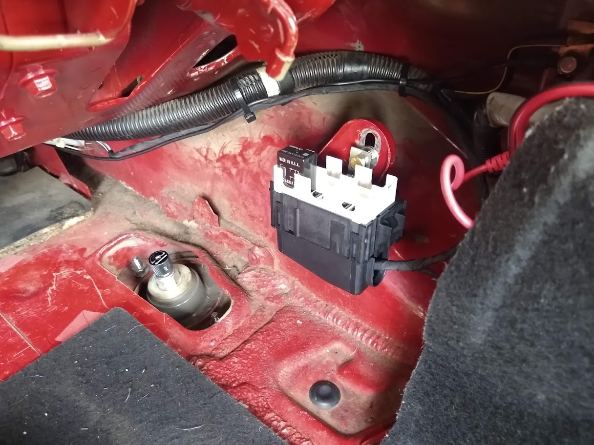
Luckily I had a neat relay box lying around so I wired that in to replace the old relay and used a higher rated relay. Still need to check if there's an abnormal resistance in the circuit causing excessive heat. The new relay still gets hot but still cold enough to touch with my fingers so hopefully I won't get the same issue again. Will also be able to add up to 5 extra relays to the box at a later date if I need to.
Old relay with integrated fuse.
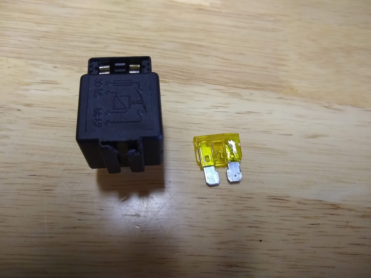
New relay box with separate fuse holder.
Received and fitted a Honed Developments brake booster delete. Very well put together kit that was quite easy to install. It comes with a new push-rod for the master cylinder and a template to drill a new mounting hole in the brake pedal to move the pivot point. The pedal feels a bit stiffer but I quickly got used it it. It feels much easier to control brake pressure now and the pedal feels much more linear.
I also fitted a new heat exchanger for the inter-cooler which bolted right up to the A/C condenser brackets. It should be much more effective than the A/C condenser however both barbs are on the same end-tank and I don't believe there is any internal baffling to split the end-tank to make it a true dual core radiator. If I run the pump to circulate coolant through it the air temperature rises fairly quickly on boost however if I leave the pump off so that the water in the radiator cools and then turn the pump on in boost the temperature stays quite stable for a while. Plan is to cap one of the barbs off and add a new one on the other side so that the water will flow properly through the core. I guess I should expect this sort of thing from eBay parts
I then capped one of the barbs off and then drilled/tapped and added a new fitting to the other side to allow the water to flow across the core properly.
I've also moved to a new low mount Kraken manifold as I preferred the design over the high mount version. I needed to make a new longer oil feed line, change the oil drain for a shorter one (was sent a long one by mistake originally but it worked out anyway). Also had to clock the turbo bearing housing to get the drain on the bottom as well as the compressor outlet to point down again.
Due to the position of the turbo now the compressor inlet has interference with the water pump inlet housing. Luckily since I had already modified it to delete the heater return pipe it was an easy job flipping it the other way around to get it out of the way.
I decided to keep the oil feed on source from the VVT actuator since it was easier to just leave it there than run it down to the oil pressure sensor port which was my original plan.
Unfortunately I didn't have the right silicone bends to have the compressor outlet facing down. Limited room down there since the subframe and water pump is quite close and there' a limited angle the compressor can be clocked to due to the wastegate actuator. For now I've just got it pointed out the side.
Accessing all the bolts and fittings is so much more difficult than the 'high' mount version of the manifold. Luckily there was still half decent access to the dump pipe bolts and oil feed fitting to tighten them but the water and drain fittings had to be tightened to the manifold before it was lowered in. I'll look into different fittings to connect the water lines since it's not ideal having to take the manifold off to loosen or tighten them.
Also while everything was off and I had good access I swapped the engine mount for an innovative poly one. Annoyingly it didn't clear the dipstick tube so I had to grind it down for clearance. Not sure Why that would be the case.
Went to take it for a test drive the other day and fill the tank up since the fuel that was in there was quite old. Ended up stalling when I got back home and wouldn't restart. Checked the data and it went lean for no apparent reason. Waited about 30min and restarted and left it idling and stalled again after about 10min. Unfortunately I haven't got a fuel pressure sensor but from what I could tell it was losing pressure. Had a look at the fuel pump relay and the fuse and contact in the relay had melted a bit. Looked like it was getting too hot.
Luckily I had a neat relay box lying around so I wired that in to replace the old relay and used a higher rated relay. Still need to check if there's an abnormal resistance in the circuit causing excessive heat. The new relay still gets hot but still cold enough to touch with my fingers so hopefully I won't get the same issue again. Will also be able to add up to 5 extra relays to the box at a later date if I need to.
Old relay with integrated fuse.
New relay box with separate fuse holder.
Reply
0
0
01-31-2021, 05:26 PM
#63
Junior Member
Thread Starter
Join Date: Jun 2015
Location: VIC, Australia
Posts: 182
Total Cats: 58
So far new relay has been working fine and isn't warming up much however still keeping a few spare relays in the glove box just in case. I inspected all the wiring to the pump and in the tank and there's no issues there. Contacts on the old relay must have just been crap.
Driving with the re-routed W2A heat exchanger it seems to be working fairly well although I haven't driven it too hard yet. Last time I took the car out ambient temperature was about 21degC and the highest intake temperature I saw was about 40degC with the water pump turning on at 35degC.
About 10 seconds at full throttle with a temperature rise of under 9degC. It also seems to plateau fairly quickly and barely increased after the gear change.
Also made a heatshield for the new manifold out of a 2 layer embossed aluminium material to reduce the temperature of the surrounding components. Very easy to cut and bend to the correct shape.
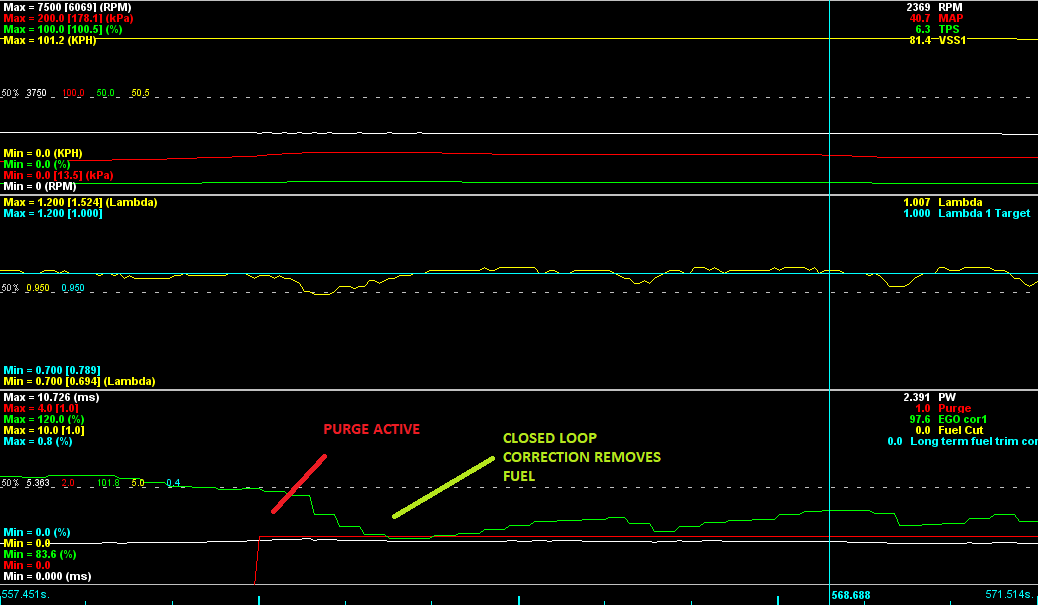
I had a spare output in the engine bay that I used to use for the A/C fan which I've since removed so decided to connect the output to the purge solenoid in order to vent the charcoal canister. When active it has a small impact to the amount of fuel required to be injected and the closed loop correction removes about 5% or so depending on load and how saturated the canister is. At the moment I've got it active during cruise RPMs and load. Should make a small difference to fuel economy although I'm not sure how noticeable it will be. At least I can prevent a buildup of fumes/pressure in the fuel tank.
Driving with the re-routed W2A heat exchanger it seems to be working fairly well although I haven't driven it too hard yet. Last time I took the car out ambient temperature was about 21degC and the highest intake temperature I saw was about 40degC with the water pump turning on at 35degC.
About 10 seconds at full throttle with a temperature rise of under 9degC. It also seems to plateau fairly quickly and barely increased after the gear change.
Also made a heatshield for the new manifold out of a 2 layer embossed aluminium material to reduce the temperature of the surrounding components. Very easy to cut and bend to the correct shape.
I had a spare output in the engine bay that I used to use for the A/C fan which I've since removed so decided to connect the output to the purge solenoid in order to vent the charcoal canister. When active it has a small impact to the amount of fuel required to be injected and the closed loop correction removes about 5% or so depending on load and how saturated the canister is. At the moment I've got it active during cruise RPMs and load. Should make a small difference to fuel economy although I'm not sure how noticeable it will be. At least I can prevent a buildup of fumes/pressure in the fuel tank.
Reply
0
0
02-18-2021, 04:10 AM
#64
Junior Member
Thread Starter
Join Date: Jun 2015
Location: VIC, Australia
Posts: 182
Total Cats: 58
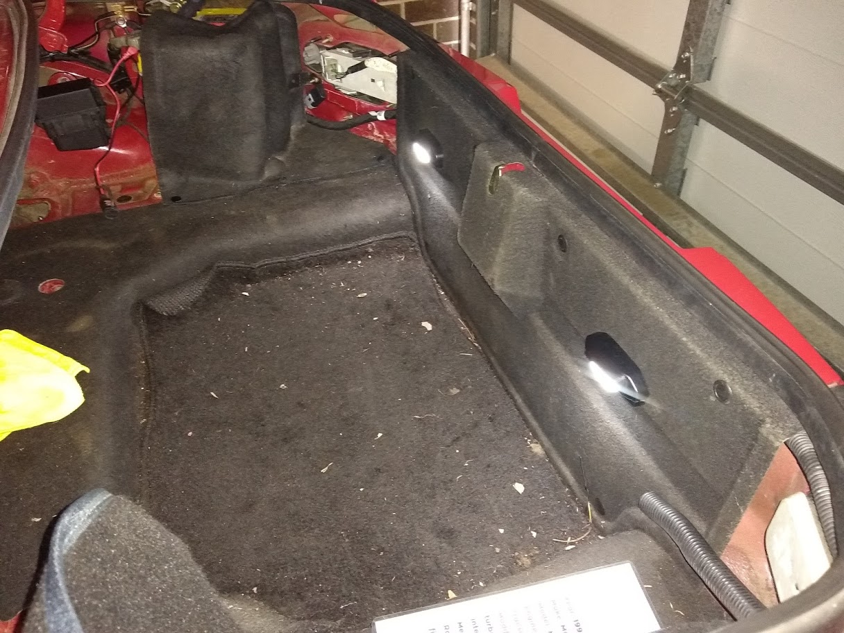
Installed some boot lighting I've had sitting around for years and never got around to fitting up so I no longer need to use a flashlight when it's dark. Pretty simple wiring, just power ground and a trigger circuit between them so they both turn on at the same time. Since they turn on/off with capacitive touch there wasn't any need to connect up a switch for when the boot is opened.
I also sold my MS3Pro to a friend and made an adapter board since his car is an NB8B. I designed it with an onboard MAP and baro sensor since the gen1 pro doesn't have an inbuilt sensor.
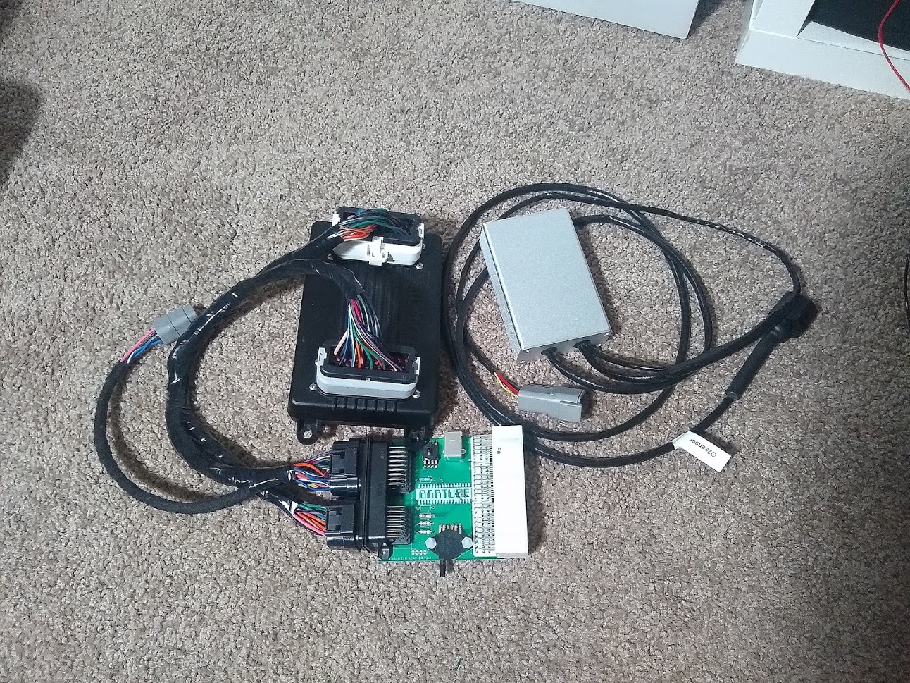
Also made another one for myself however it doesn't plug into a Megasquirt...
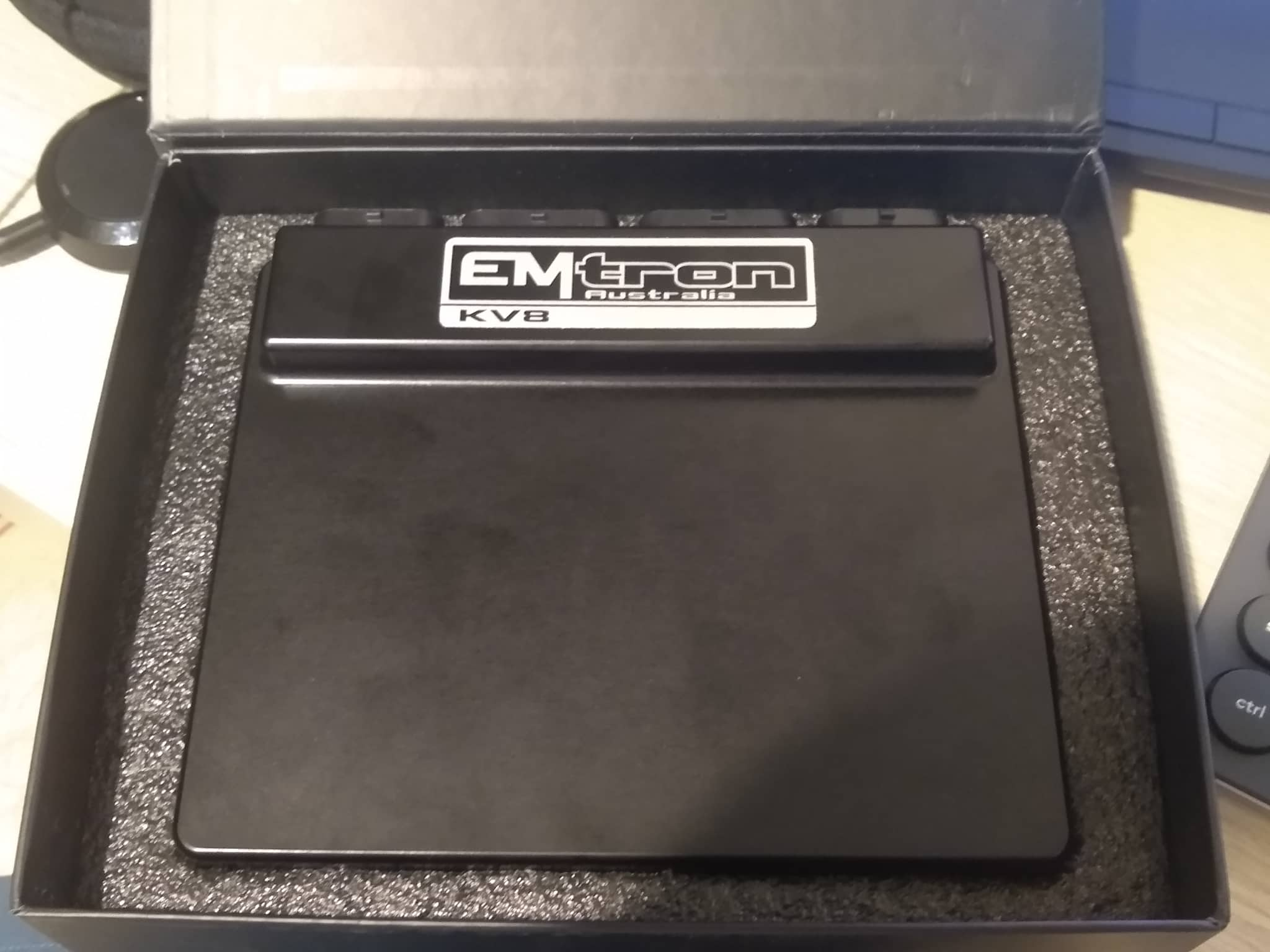
...plugs into this. Picked it up when there was a special on and am keen to get it fitted and have a play around with it. Will let me convert to drive by wire in the future. I was considering just wiring it straight into the car but this way I can at least swap the MS back in if I run into any trouble with the initial setup and want to drive it.
I've only bench tested it so far but the software seems far more flexible than MS, allowing you to modify the x/y axis of any table to whatever you want, customise how many cells are available and also has a number of z axes for many tables. It also has tables for closed-loop PID control so you're not stuck with one value and can change the gains depending on the target error.
There's a whole heap of extra control you can add over what MS3 can do however it will come with extra complexity in calibrating it all.
For example MS3s over-run fuel cut was pretty basic, allowing you to cut fuel below xTPS and above an RPM range based on RPM rate of change.
Emtron will cut fuel when below xTPS as well but also allows you to use the vehicle speed as another control input and create a separate enable and disable RPM table based on vehicle speed and whatever else you might want like coolant temperature as well an activation delay table you can set up how you want.
Only downside I've noticed so far is that it doesn't yet seem to have an alternator control function I can use with the NB alternator however I've set up a 'user function' table to control it anyway so will see how that works. It will be open-loop control instead of the MS3 closed-loop control but I've still managed to set up a post start delay and hopefully will be able to calibrate the table to achieve a stable voltage.
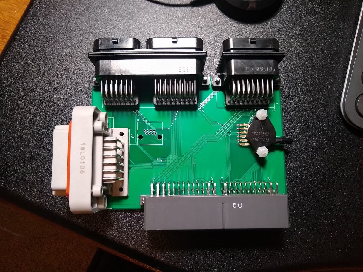
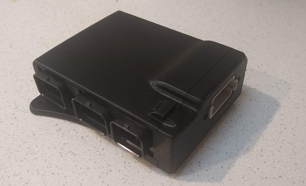
Originally I was going to just hot glue the exposed contacts on the Emtron adapter board I made but ended up buying a 3D printer the other day so I decided to design a nice case for it instead.
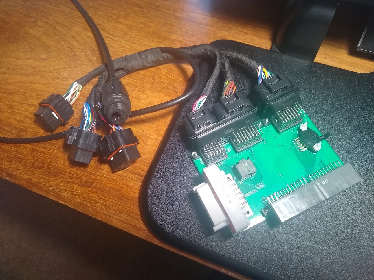
Luckily I could export the circuit board as a 3D model and all the component CAD was available so it was pretty simple to model the PCB. It seems accurate when checking with vernier calipers and I've hopefully allowed for enough tolerance in their positions.
PCB with all the components fitted.
https://i.imgur.com/2negDgX.jpg
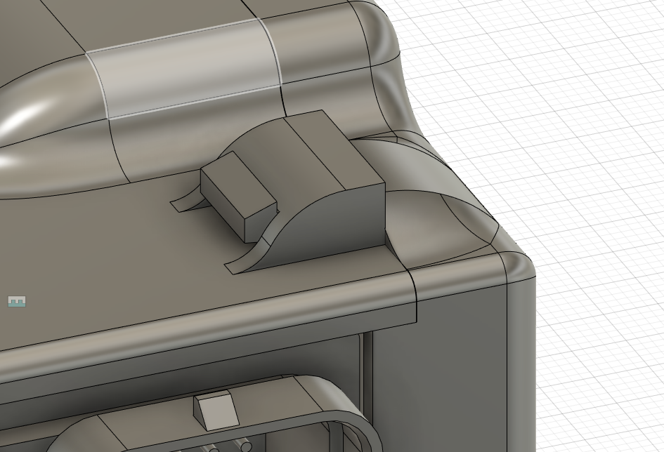
The case is made of 3 parts, a main section the PCB slides into, a cover that clips on and a little insert to cover a cavity between two of the connectors.
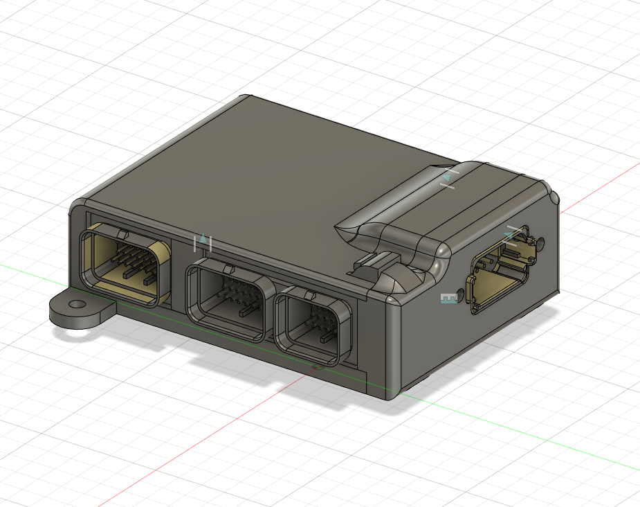
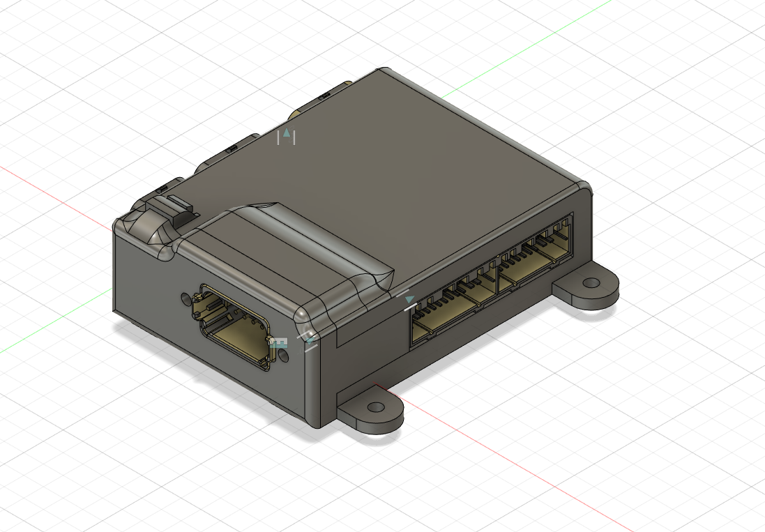
Hopefully the clips end up working ok. They just push in and should click into place if it all works properly.
...just have to wait for the printer to arrive.
Patch harness is also done but I will still need to wire up the last connector on the Emtron to a Bosch LSU 4.9 O2 sensor. Just waiting on the connector to arrive. I made sure to get the gold plated terminals for the sensor to prevent any dissimilar metal corrosion since the O2 connector uses gold terminals.
Might notice there's an RJ45 connector on the PCB board as well as one coming from the patch harness. When I designed the PCB I used a footprint for a 90deg connector by accident, which the cable won't fit into due to how close the other connectors are. None of the straight connector footprints lined up with it so it won't be used.
I also sold my MS3Pro to a friend and made an adapter board since his car is an NB8B. I designed it with an onboard MAP and baro sensor since the gen1 pro doesn't have an inbuilt sensor.
Also made another one for myself however it doesn't plug into a Megasquirt...
...plugs into this. Picked it up when there was a special on and am keen to get it fitted and have a play around with it. Will let me convert to drive by wire in the future. I was considering just wiring it straight into the car but this way I can at least swap the MS back in if I run into any trouble with the initial setup and want to drive it.
I've only bench tested it so far but the software seems far more flexible than MS, allowing you to modify the x/y axis of any table to whatever you want, customise how many cells are available and also has a number of z axes for many tables. It also has tables for closed-loop PID control so you're not stuck with one value and can change the gains depending on the target error.
There's a whole heap of extra control you can add over what MS3 can do however it will come with extra complexity in calibrating it all.
For example MS3s over-run fuel cut was pretty basic, allowing you to cut fuel below xTPS and above an RPM range based on RPM rate of change.
Emtron will cut fuel when below xTPS as well but also allows you to use the vehicle speed as another control input and create a separate enable and disable RPM table based on vehicle speed and whatever else you might want like coolant temperature as well an activation delay table you can set up how you want.
Only downside I've noticed so far is that it doesn't yet seem to have an alternator control function I can use with the NB alternator however I've set up a 'user function' table to control it anyway so will see how that works. It will be open-loop control instead of the MS3 closed-loop control but I've still managed to set up a post start delay and hopefully will be able to calibrate the table to achieve a stable voltage.
Originally I was going to just hot glue the exposed contacts on the Emtron adapter board I made but ended up buying a 3D printer the other day so I decided to design a nice case for it instead.
Luckily I could export the circuit board as a 3D model and all the component CAD was available so it was pretty simple to model the PCB. It seems accurate when checking with vernier calipers and I've hopefully allowed for enough tolerance in their positions.
PCB with all the components fitted.
https://i.imgur.com/2negDgX.jpg
The case is made of 3 parts, a main section the PCB slides into, a cover that clips on and a little insert to cover a cavity between two of the connectors.
Hopefully the clips end up working ok. They just push in and should click into place if it all works properly.
...just have to wait for the printer to arrive.
Patch harness is also done but I will still need to wire up the last connector on the Emtron to a Bosch LSU 4.9 O2 sensor. Just waiting on the connector to arrive. I made sure to get the gold plated terminals for the sensor to prevent any dissimilar metal corrosion since the O2 connector uses gold terminals.
Might notice there's an RJ45 connector on the PCB board as well as one coming from the patch harness. When I designed the PCB I used a footprint for a 90deg connector by accident, which the cable won't fit into due to how close the other connectors are. None of the straight connector footprints lined up with it so it won't be used.
Last edited by Barton; 02-18-2021 at 02:37 PM.
Reply
2
2
 02-18-2021, 04:49 PM
#67
Junior Member
Thread Starter
Join Date: Jun 2015
Location: VIC, Australia
Posts: 182
Total Cats: 58
I paid a bit under $2200USD at the current exchange rate. Fair bit more expensive than an MS3 but once you add costs for a DBW module and IO expander the difference isn't as big.
Last edited by Barton; 02-22-2021 at 03:21 AM.
Reply
1
1
02-18-2021, 06:03 PM
#68
Senior Member

Join Date: Aug 2017
Location: Norwich NY
Posts: 635
Total Cats: 322
Compared to a haltech at regular pricing that is pretty much in line. In freedom eagles, you are looking at 1500 for a bare 1500 Elite or 1800 with a PNP harness. Add 300 for a WB box, and an I/O expander is another 336 bucks, so with a bare ECU, WB and I/O box you are at 2100 bucks (although I did not compare the native number of I/O) - and although not relevant on a miata, that is comparable to an Elite 2500 with the 8 cyl support and it also has oscilloscope function. Good stuff!

Reply
0
0
02-18-2021, 06:22 PM
#69
Supporting Vendor

iTrader: (10)
Join Date: Aug 2014
Location: Bainbridge Island, WA
Posts: 1,461
Total Cats: 388
That's a serious big boy ecu.
Funny, in my swap I eschewed the typical GM DBW setup in favor of the simpler MS3+cable throttle setup. To each their own.
Funny, in my swap I eschewed the typical GM DBW setup in favor of the simpler MS3+cable throttle setup. To each their own.
__________________

Reply
0
0
02-19-2021, 02:24 AM
#70
Junior Member
Thread Starter
Join Date: Jun 2015
Location: VIC, Australia
Posts: 182
Total Cats: 58
In aussie dollarydoos the Elite 1500 is just under $2000 while the Emtron KV8 is just under $3000 normally so a bit of a price difference. There's also an SL series which is closer in price but it has less I/O and doesn't include the integrated wideband controller. It's definitely more comparable to an Elite 2500 although the KV8 has 4 more digital outputs, 6 more analog inputs and 10 more digital inputs if I'm reading it correctly, as well as the same injector/spark outputs.
I did consider getting an Elite 1500 instead but I didn't like how overly simple the drive by wire to pedal calibration worked among other things.
Hopefully I will make good use of all the extra I/O the new ECU will give. So far I've got
Outputs:
- 4x injectors
- 2x spark (will move to sequential later)
- Fuel pump relay control
- Boost solenoid control
- Idle valve control (will be removed when DBW throttle fitted)
- VVT solenoid control
- Speedo gauge control
- Tacho gauge control
- Oil pressure gauge control
- Thermofan relay control
- Engine water pump control
- Charge air cooler pump control
- Check engine lamp
- Alternator control
- Purge solenoid control
Inputs:
- MAP sensor
- MAT sensor
- Knock sensor
- Cam position sensor
- Crank position sensor
- Flex fuel sensor
- MAF sensor
- MAF temperature sensor
- Brake switch
- Clutch switch
- Gearbox output speed
- Engine oil temperature sensor
- Engine oil pressure sensor
- Engine coolant temperature sensor
- Baro sensor (internal)
Then once I fit an electronic throttle I'll also add
- Pedal position 1 sensor
- Pedal position 2 sensor
- Throttle position 1 sensor
- Throttle position 2 sensor
- Pre-throttle pressure sensor
- ETC relay control
Reply
2
2
02-23-2021, 03:51 AM
#71
Junior Member
Thread Starter
Join Date: Jun 2015
Location: VIC, Australia
Posts: 182
Total Cats: 58
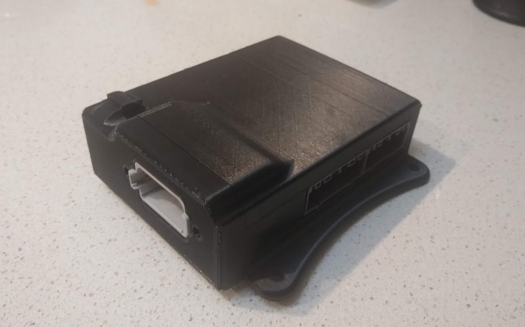
Got my printer on the weekend and after some initial setup and testing I printed the case. It came out looking pretty good and fit together perfectly.
Just need to find some time to fit the Emtron to the car and start testing. Still waiting on the O2 connector though.
Just need to find some time to fit the Emtron to the car and start testing. Still waiting on the O2 connector though.
Reply
3
3
03-11-2021, 03:18 AM
#72
Junior Member
Thread Starter
Join Date: Jun 2015
Location: VIC, Australia
Posts: 182
Total Cats: 58
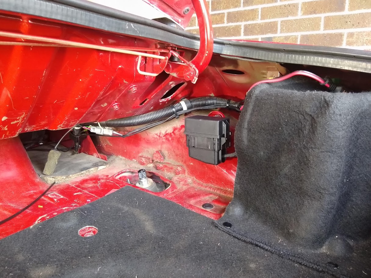
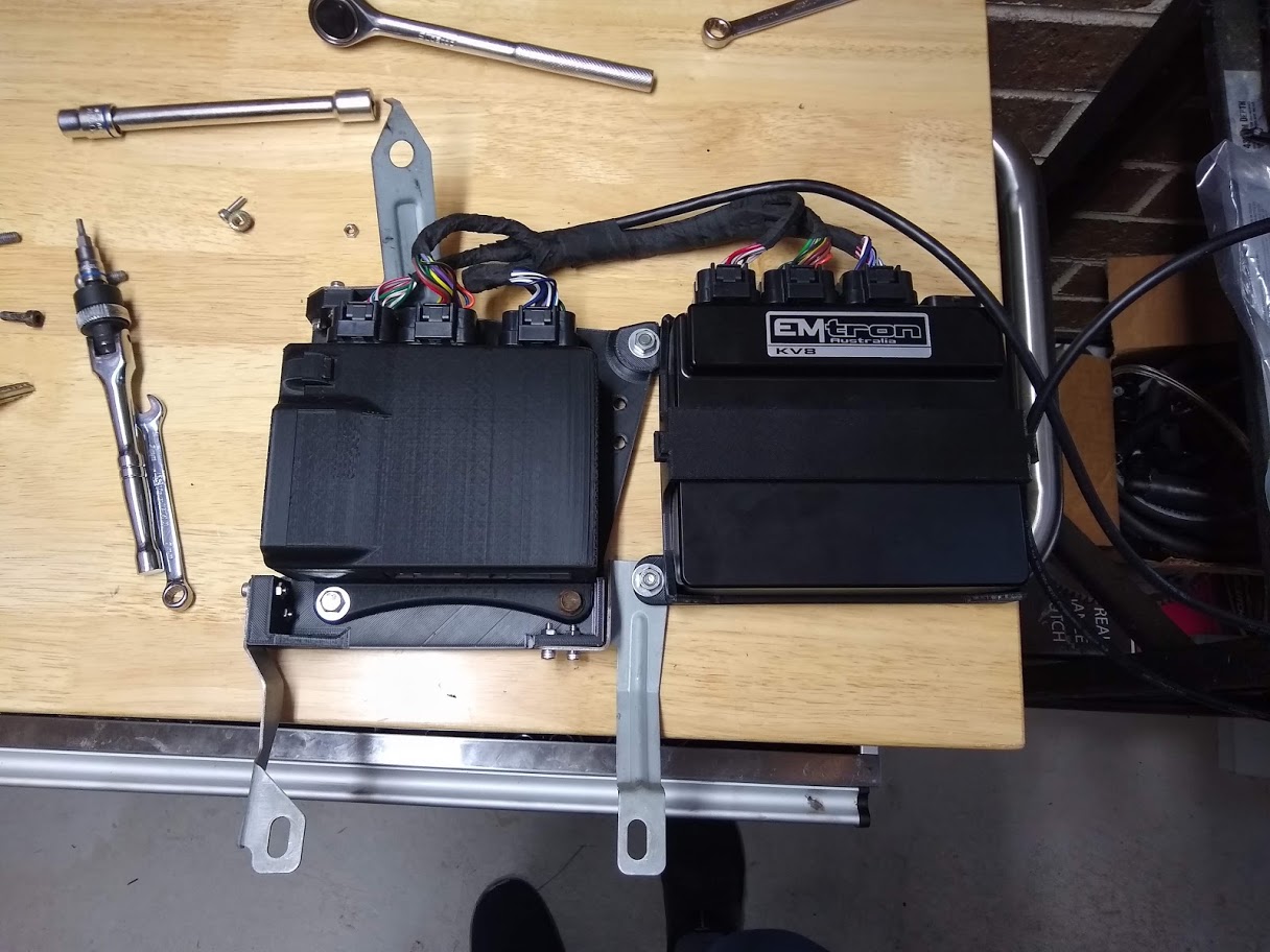
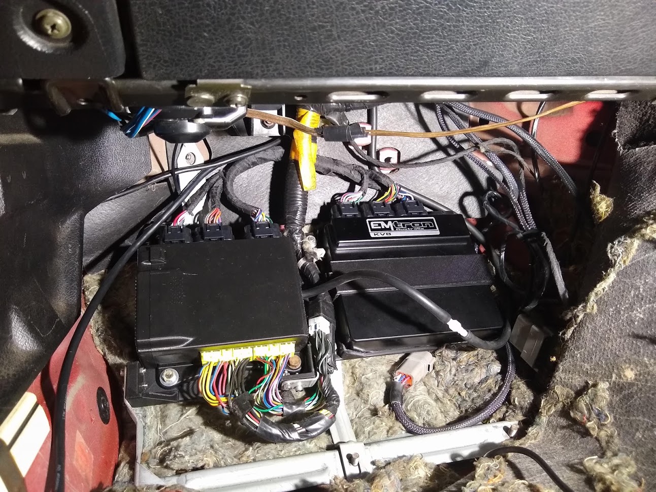
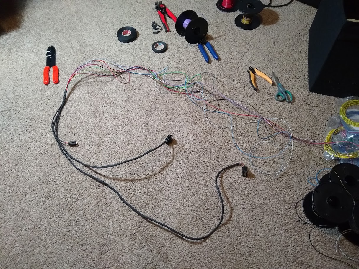
I went a step further and designed/printed a bracket for the Emtron as well as a base bracket for them all to attach to using the original ECU mounts in the footwell. Worked out pretty well although looking at the mess of wiring from all the incremental changes I've made over the years makes me cringe. Will be cleaning that up once I'm ready to run on the Emtron.
I powered it up to test all the I/O and it all seemed good except when I want to turn the ignition off the radiator fan turned on and backfed power through the controller keeping it all alive. Moved the fan output to a different aux output pin and it was all fixed. Also managed to get it started and idling fine on the base map I put together.
I powered it up to test all the I/O and it all seemed good except when I want to turn the ignition off the radiator fan turned on and backfed power through the controller keeping it all alive. Moved the fan output to a different aux output pin and it was all fixed. Also managed to get it started and idling fine on the base map I put together.
Reply
1
1
04-17-2021, 02:07 AM
#73
Junior Member
Thread Starter
Join Date: Jun 2015
Location: VIC, Australia
Posts: 182
Total Cats: 58
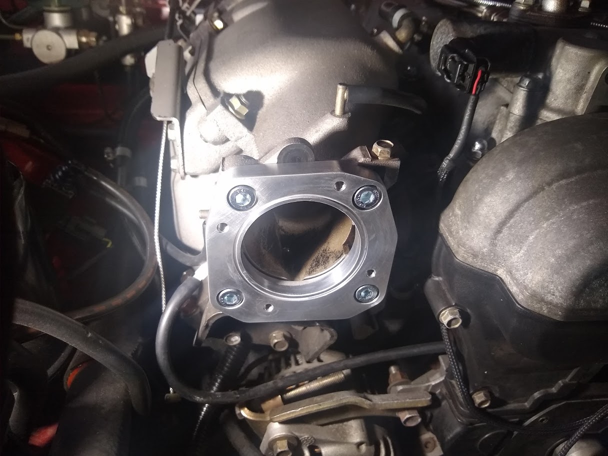
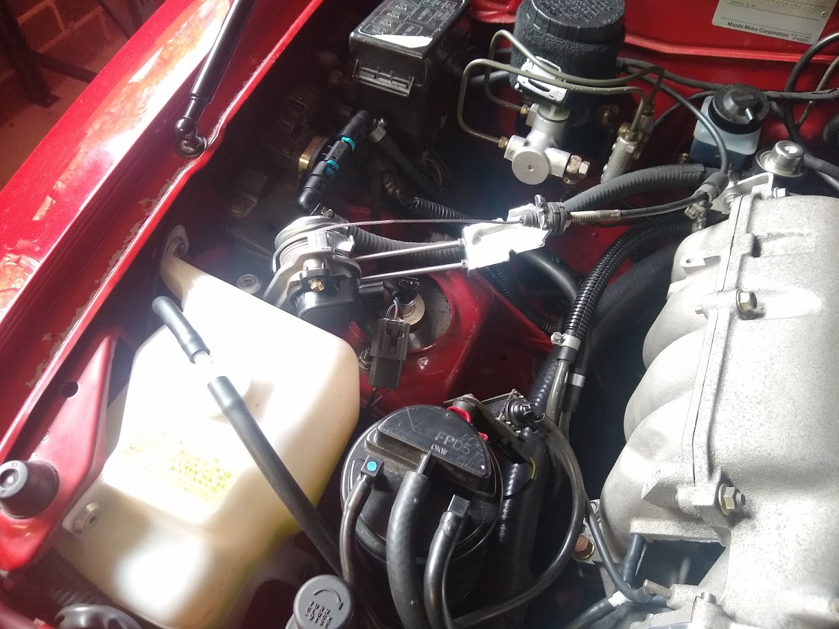
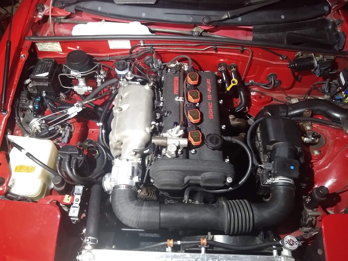
I've always wanted to convert to drive by wire and I'm finally able to now. With the help of a generous friend who designed an adapter plate, I fitted a Bosch 60mm drive by wire throttle body to the OEM intake manifold. The adapter puts the new throttle body on a bit of an angle but the bore lines up perfectly.
Ideally I would have also fit an electronic accelerator pedal as well but I found this Honda Accord sensor that accepts a cable throttle and has a position sensor with redundancy. It seems to have been when Honda moved to drive by wire on the accord part way through a model year so instead of changing the pedal assembly they added this sensor instead. Perfect for me since it means I don't need to mess around with adapting a new pedal to the car. At some point in the future I will look at moving to an electronic pedal though but for now this is convenient.
I did need to extend out the cable bracket from where it normally sits on the sensor due to the length.
Next step is to wire the throttle and pedal senor to the ECU. Should be fun to play around with once it's all setup and working with the new ECU.
Reply
4
4
05-28-2021, 01:53 AM
#74
Junior Member
Thread Starter
Join Date: Jun 2015
Location: VIC, Australia
Posts: 182
Total Cats: 58
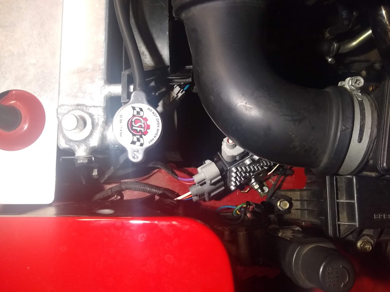
Wired up the throttle body and pedal sensor as well as a fuel pressure sensor since I was always planning on wiring one in anyway.
Somehow made a mistake with the ETC motor +/- circuits and initially had them the wrong way around. Easy fix but it caused the ECU to think that the closed position was 100% and open was 0%.
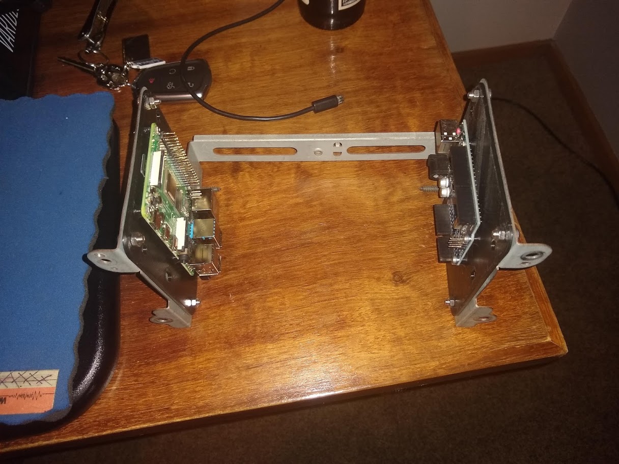
I've also been working on adding a raspberry pi display to the tombstone using a kit from digi-ata. It places the display in a much more visible area than the original radio and will allow me to run android auto from it.
The pi and an arduino to control the power and lighting will mount where the original radio goes with some 3d printed brackets.
I've designed a circuit board to handle the power control for the Pi using the ardiuno as well as control dimming when the lights are on. Will just use a relay to hold constant power on while the Pi shuts down when you turn off the key.
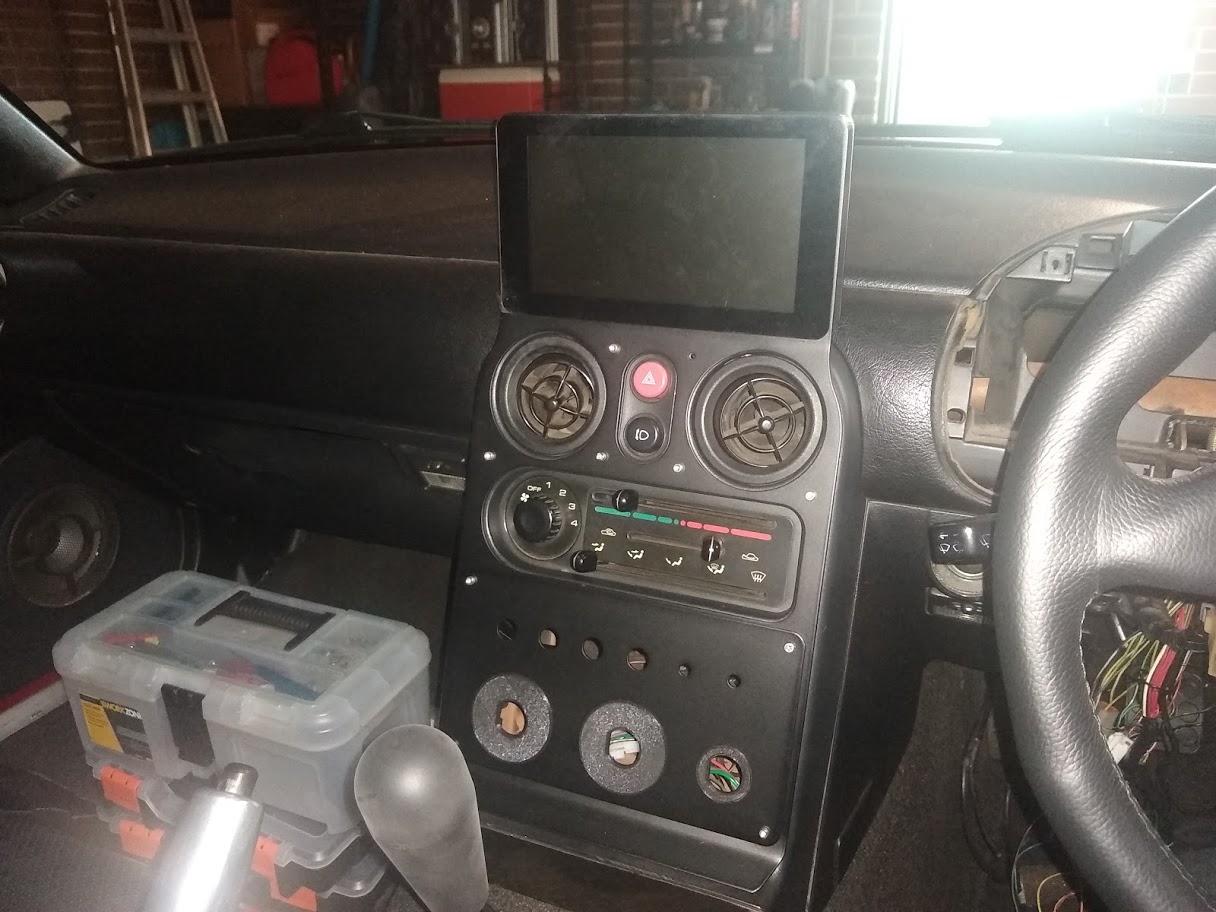
Might also notice the dash is missing. Unfortunately the raspberry pi and display I was using for the dash isn't compatible with the new ECU, unless I write new software to display data over CAN bus so will be fitting an NB instrument panel instead.
Somehow made a mistake with the ETC motor +/- circuits and initially had them the wrong way around. Easy fix but it caused the ECU to think that the closed position was 100% and open was 0%.
I've also been working on adding a raspberry pi display to the tombstone using a kit from digi-ata. It places the display in a much more visible area than the original radio and will allow me to run android auto from it.
The pi and an arduino to control the power and lighting will mount where the original radio goes with some 3d printed brackets.
I've designed a circuit board to handle the power control for the Pi using the ardiuno as well as control dimming when the lights are on. Will just use a relay to hold constant power on while the Pi shuts down when you turn off the key.
Might also notice the dash is missing. Unfortunately the raspberry pi and display I was using for the dash isn't compatible with the new ECU, unless I write new software to display data over CAN bus so will be fitting an NB instrument panel instead.
Reply
0
0
06-24-2021, 06:17 PM
#75
Junior Member
Thread Starter
Join Date: Jun 2015
Location: VIC, Australia
Posts: 182
Total Cats: 58
Finally finished off the raspberry pi multimedia control. I was waiting on a hifiberry amp2 to power the speakers and a little circuit board I designed for the Arduino control. Also had to wire up two DPDT switches to control the window motors.
Initially the Arduino was supposed to communicate to the Raspberry Pi to shutdown and control the display brightness through the GPIO pins but I realised that I could just plug the Arduino USB into the Pi and use the serial communication and save me from having to run extra wires. After a bit of stuffing around writing a Python script to receive and interpret the serial comms I had it working.
I've got it setup so that when the key turns to ACC the Pi boots up and then when the key is turned OFF the Pi shutdown after a 1 minute delay, and then the power is cut.
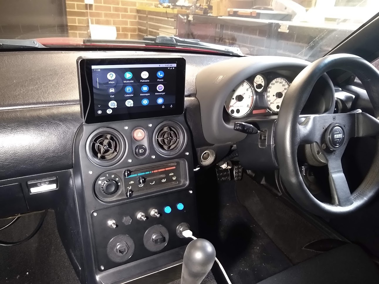
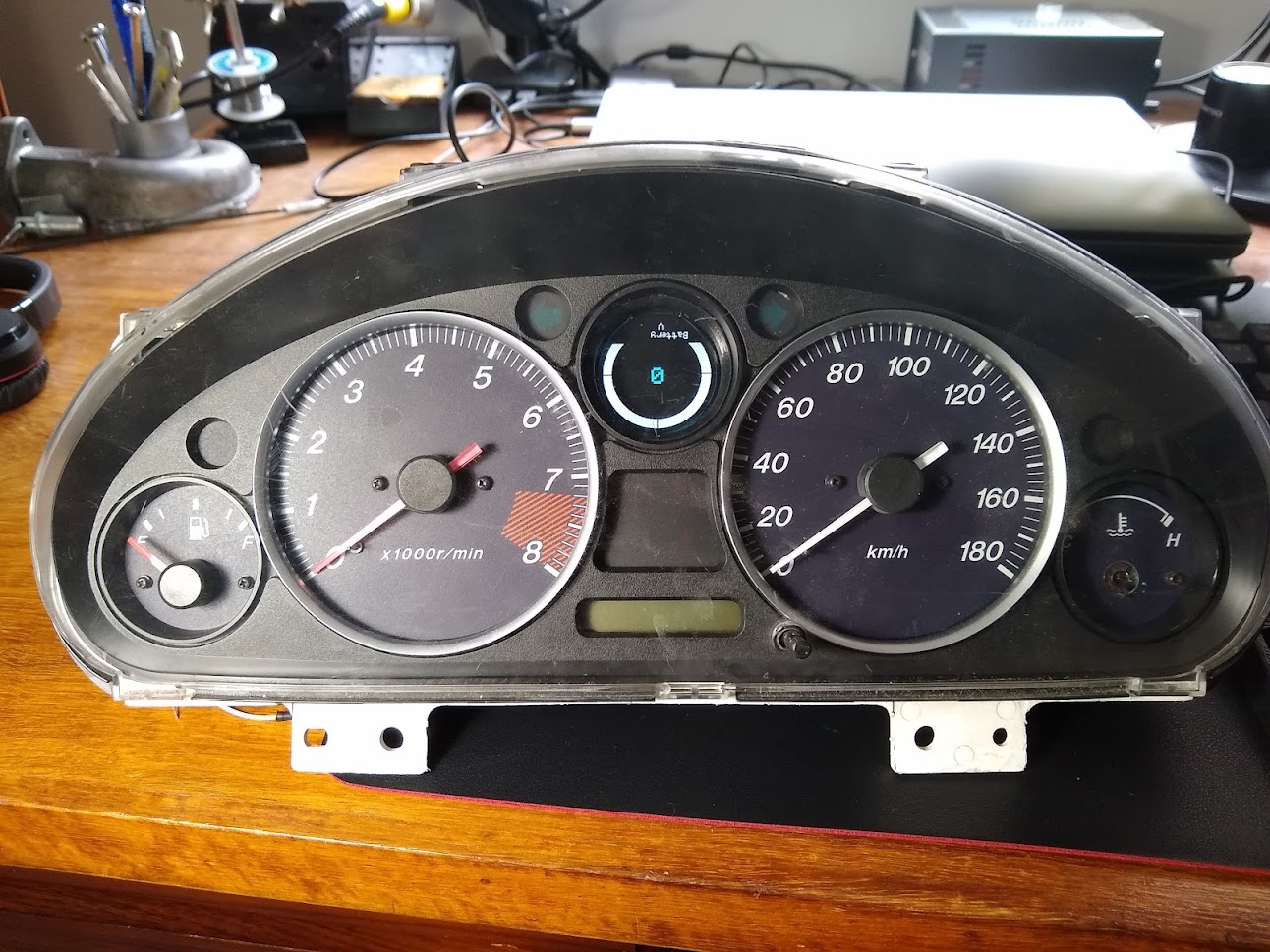
Wired up an NB dash as well and setup a neat gauge sweep function in the ECU for it. Unfortunately this dash didn't have a CEL so the airbag light will be used for that.
I'm also close to getting the engine ready to start and begin calibrating the new ECU. I still have a few circuits to swap around on the ECU connector since I used the wrong output.
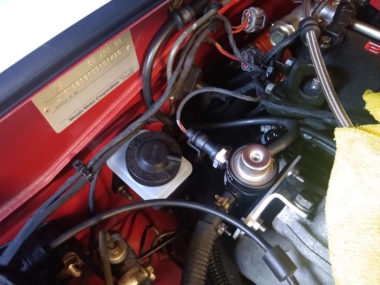
Fuel pressure sensor arrived as well so that's fitted and will help the ECU inject the correct amount of fuel if the pressure fluctuates.
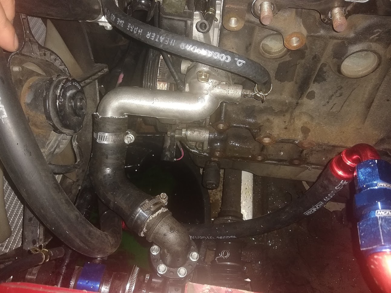
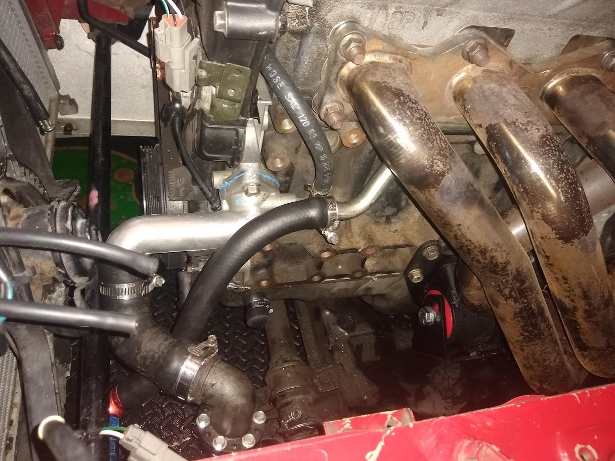
Re-routed the heater return since I no longer wanted it to run through the turbo. I used the original hard pipe but stuck a hose on the end of it so that it could return to the pump inlet.
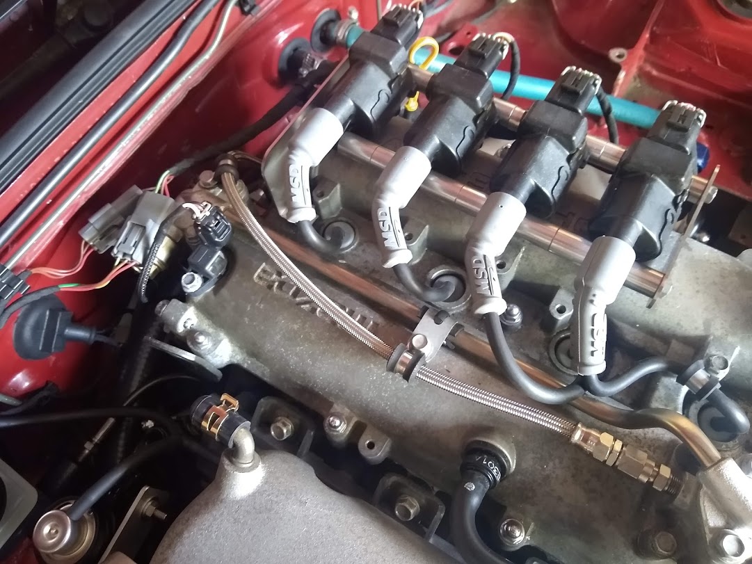
Received the new FlowForce R8 coil kit so that got fitted up too. A bit neater than the LS coils and no more plug wires.
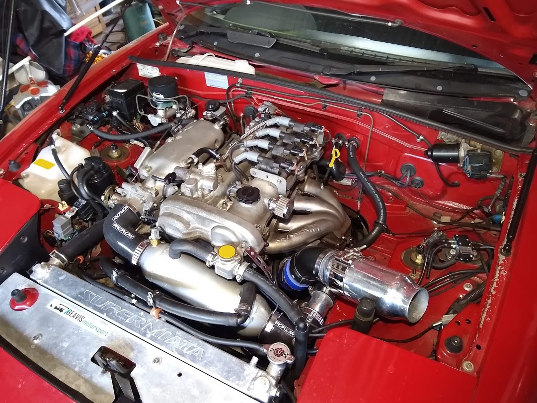
You'll notice in that last picture that the turbo is missing! I decided I'd start off tuning the new ECU n/a to help simplify the process a bit and reduce the risk of me damaging anything while I'm learning the software.
Initially the Arduino was supposed to communicate to the Raspberry Pi to shutdown and control the display brightness through the GPIO pins but I realised that I could just plug the Arduino USB into the Pi and use the serial communication and save me from having to run extra wires. After a bit of stuffing around writing a Python script to receive and interpret the serial comms I had it working.
I've got it setup so that when the key turns to ACC the Pi boots up and then when the key is turned OFF the Pi shutdown after a 1 minute delay, and then the power is cut.
Wired up an NB dash as well and setup a neat gauge sweep function in the ECU for it. Unfortunately this dash didn't have a CEL so the airbag light will be used for that.
I'm also close to getting the engine ready to start and begin calibrating the new ECU. I still have a few circuits to swap around on the ECU connector since I used the wrong output.
Fuel pressure sensor arrived as well so that's fitted and will help the ECU inject the correct amount of fuel if the pressure fluctuates.
Re-routed the heater return since I no longer wanted it to run through the turbo. I used the original hard pipe but stuck a hose on the end of it so that it could return to the pump inlet.
Received the new FlowForce R8 coil kit so that got fitted up too. A bit neater than the LS coils and no more plug wires.
You'll notice in that last picture that the turbo is missing! I decided I'd start off tuning the new ECU n/a to help simplify the process a bit and reduce the risk of me damaging anything while I'm learning the software.
Reply
3
3
07-21-2021, 08:15 PM
#76
Junior Member
Thread Starter
Join Date: Jun 2015
Location: VIC, Australia
Posts: 182
Total Cats: 58
So I've got it started and idling well now. Still needs some work on the cold start but hot start and idle is quite good. Getting the alternator control setup has been a bit annoying though since the software does not yet have a closed-loop alternator control function. Looks like there's a placeholder for it but nothing there yet so I've had to set up a generic open-loop output to control the alternator which isn't ideal since the electrical load isn't always going to be constant. Worst case I have a few options. Either add a hardware board to control it directly, add a CAN module to perform the control and command the duty cycle output from the ECU or swap to an NA8 alternator.
I've had this Mazda/Mitsubishi fan module sitting around for ages so I decided to wire that up to the radiator fan to soft start the fan and control the speed to reduce the inrush current when it turns on. Prevents me having to adjust the alternator output as it starts to prevent a voltage dip.
It's a smart module so even if you didn't want to connect the speed control input circuit it can be used to slowly ramp up the fan speed when it turns on. I've heard these things might not be the most reliable so I've made sure that I can easily bypass the module just in case it fails.
I noticed when I shut the engine off it's bit rough due to the throttle losing power and moving to the default position (5.5%) so I can wire up a relay to the ignition barrel circuit to hold ECU power as the engine shuts off. I wasn't sure if I needed it or not but it will allow the throttle to be held shut for smoother shut off and also allows the fan and pump to continue running after the key is off. The ECU has an inbuilt function for this so the after run timer can be adjusted. Once the timer is exceeded the ECU will turn the relay off. After that I think I'm done with wiring for now....hopefully.
I've also started calibrating the throttle mass flow (TMF) function in the ECU and it's really neat. It uses a throttle position vs throttle area curve and pressure sensors before and after the throttle to calculate mass airflow through the throttle. This means I just have to adjust the throttle % vs area curve and the ECU will determine the mass of fuel to inject based on the calculated airflow. Works really well however can't be used at high pressure ratios across the throttle (near atmosphere manifold pressure) so I'll have to blend in either MAF or speed density (MAP) there. I've got the NB MAF working so will see how I go blending with that first. It should also work very well in transient events since it will immediately calculate the airflow change as the throttle moves unlike MAP which has a delay before the pressure in the manifold changes and MAF which has some error during transients.
Reply
2
2
08-14-2021, 04:49 AM
#77
Junior Member
Thread Starter
Join Date: Jun 2015
Location: VIC, Australia
Posts: 182
Total Cats: 58
So I've given up on controlling the alternator with the ECU and took the easy option to replace it with an internally regulated alternator.
Ideally I wanted to keep the NB one that was on there but without some sort of function in the ECU with a feedback loop it was impossible to maintain a steady voltage at varying electrical loads.
After a bit of research I ordered an alternator for an EL Falcon which should also be the same unit as an FD RX-7. Bolted right up, used the same 2-way connect, same post size and as a bonus, produces 110amps. Couple of differences like the B+ post is located on the back instead of the side but still works fine.
It also has a 5-rib pulley instead of a 4-rib and unfortunately while the shaft size is the same as the MX-5 alternator the pulley would not work since it clamped down to the housing when tightened up. Using the 5-rib pulley hopefully won't cause any issues with the belt jumping forward.
Last difference is it requires a slightly longer lower pivot bolt.
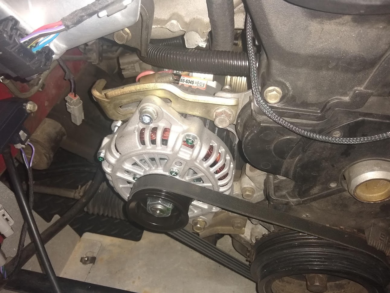
Since I'd made some wiring changes to suit the externally regulated NB alternator I had to do a bit of wiring to get it working properly. I was hoping I didn't need to make any changes since I could provide 12V from the ECU to the 'sense' circuit but turns out it also requires the lamp circuit connected to excite the alternator and start charging. Without it connected it would only start charging if the RPMs went high enough.
Luckily I still had the original NA alternator connector dangling in the engine bay so I just plugged that in and connected the lamp circuit to my dash and it all works correctly.
Ideally I wanted to keep the NB one that was on there but without some sort of function in the ECU with a feedback loop it was impossible to maintain a steady voltage at varying electrical loads.
After a bit of research I ordered an alternator for an EL Falcon which should also be the same unit as an FD RX-7. Bolted right up, used the same 2-way connect, same post size and as a bonus, produces 110amps. Couple of differences like the B+ post is located on the back instead of the side but still works fine.
It also has a 5-rib pulley instead of a 4-rib and unfortunately while the shaft size is the same as the MX-5 alternator the pulley would not work since it clamped down to the housing when tightened up. Using the 5-rib pulley hopefully won't cause any issues with the belt jumping forward.
Last difference is it requires a slightly longer lower pivot bolt.
Since I'd made some wiring changes to suit the externally regulated NB alternator I had to do a bit of wiring to get it working properly. I was hoping I didn't need to make any changes since I could provide 12V from the ECU to the 'sense' circuit but turns out it also requires the lamp circuit connected to excite the alternator and start charging. Without it connected it would only start charging if the RPMs went high enough.
Luckily I still had the original NA alternator connector dangling in the engine bay so I just plugged that in and connected the lamp circuit to my dash and it all works correctly.
Reply
0
0
08-22-2021, 06:21 PM
#78
Junior Member
Thread Starter
Join Date: Jun 2015
Location: VIC, Australia
Posts: 182
Total Cats: 58
Unfortunatley we're in covid lockdown again so can't take the car out for a proper drive to calibrate everything so have just been working on cold start and idle.
Now that I've calibrated the throttle area vs position curve, at least in the lower positions I switched over to throttle mass flow idle control. What this does is instead of the closed-loop targeting a throttle position it targets throttle airflow which is supposed to give the closed-loop PID better control since very small changes in throttle % result in large changes in airflow at idle. It also means the pedal demanded airflow can be blended in to the idle demand to smooth out the transition.
Just had to work out the initial airflow table for each target rpm from datalogs and it worked pretty well. I still need to make some adjustments for different air temperatures though.
Since we're still allowed to go grocery shopping I took it out with the laptop hooked up recording data. It drove ok but the MAF curve, pedal map, VVT PID and idle targets need a bit of work.
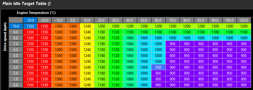
I set the idle targets based on engine temperature and vehicle speed which ended up giving a high idle when rolling in neutral to a stop. Not a huge deal but I think I will try adding a target offset if it is not in gear so that it returns down to the base idle speed.
Idle Targets:
The pedal map didn't help with this since I set the 0% pedal targets too high which made engine speed hang or even increase when I went to change gears. It actually helped a bit when downshifting but there's a seperate function for that I can enable later. Apart from that the pedal map I came up with felt pretty smooth to drive and the pedal demand filter which smooths out small pedal movements worked nicely.
Pedal map:
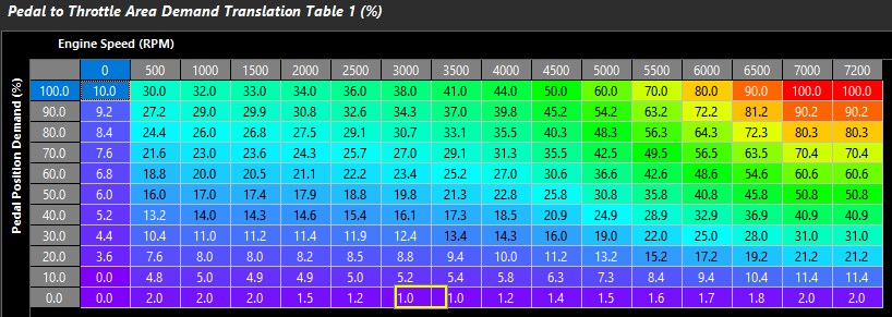
Might notice it doesn't target 100% throttle area at 100% pedal. There's no reason to do this if the manifold can be saturated at a lower area. I'll still need to modify this map later once I work out the saturation point at each engine speed column.
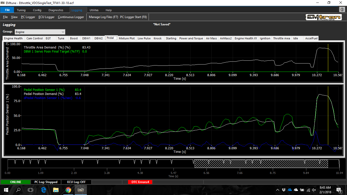
An example of how the pedal filtering works:
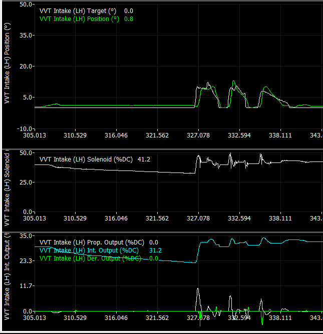
Adjusting the VVT control shouldn't be too hard since the ECU logs the outputs of each closed-loop prop, int and der outputs so it's simple to see how each gain is affecting the output. Each PID gain also has a 3D table to vary the gain depending on the target error and any other factor you want to adjust for. So for VVT control I can adjust the gains based on oil pressure or oil temperature if I need to. On the MS3 I had pretty good control while the oil was warm but not so great while it was cold. Hopefully I can improve that with the control this ECU has.
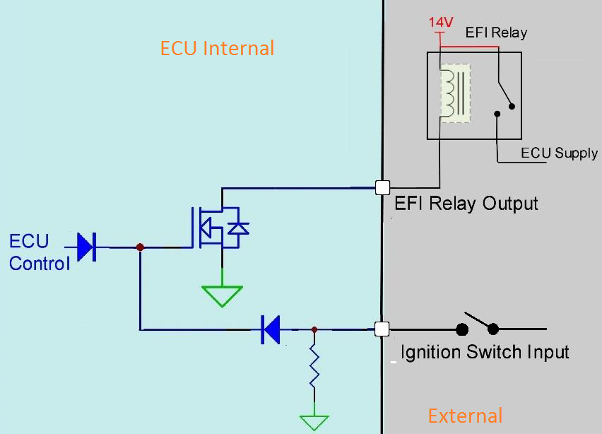
I also re-wired the ignition circuit from the key barrel to add a relay so that the ECU can control its own power source. When the key is switched on 12V is sent to the ECUs ignition switch circuit which then switches a relay that supplies power to the main relay coil. When the key is turned off the ECU holds the power on so that it can perform a few tasks (DBW calibration and internal data logging storage) as well as keep the fan running. I've set the time delay before it shuts off based on the coolant temperature and the battery voltage so it can cool the engine down for a bit without draining the battery too much.
Unfortunately I forgot that the water pumps power is sourced from the HVAC blower so it only runs while the key is in the run position but it's still nice to have the fans run after shut-off.
Now that I've calibrated the throttle area vs position curve, at least in the lower positions I switched over to throttle mass flow idle control. What this does is instead of the closed-loop targeting a throttle position it targets throttle airflow which is supposed to give the closed-loop PID better control since very small changes in throttle % result in large changes in airflow at idle. It also means the pedal demanded airflow can be blended in to the idle demand to smooth out the transition.
Just had to work out the initial airflow table for each target rpm from datalogs and it worked pretty well. I still need to make some adjustments for different air temperatures though.
Since we're still allowed to go grocery shopping I took it out with the laptop hooked up recording data. It drove ok but the MAF curve, pedal map, VVT PID and idle targets need a bit of work.
I set the idle targets based on engine temperature and vehicle speed which ended up giving a high idle when rolling in neutral to a stop. Not a huge deal but I think I will try adding a target offset if it is not in gear so that it returns down to the base idle speed.
Idle Targets:
The pedal map didn't help with this since I set the 0% pedal targets too high which made engine speed hang or even increase when I went to change gears. It actually helped a bit when downshifting but there's a seperate function for that I can enable later. Apart from that the pedal map I came up with felt pretty smooth to drive and the pedal demand filter which smooths out small pedal movements worked nicely.
Pedal map:
Might notice it doesn't target 100% throttle area at 100% pedal. There's no reason to do this if the manifold can be saturated at a lower area. I'll still need to modify this map later once I work out the saturation point at each engine speed column.
An example of how the pedal filtering works:
Adjusting the VVT control shouldn't be too hard since the ECU logs the outputs of each closed-loop prop, int and der outputs so it's simple to see how each gain is affecting the output. Each PID gain also has a 3D table to vary the gain depending on the target error and any other factor you want to adjust for. So for VVT control I can adjust the gains based on oil pressure or oil temperature if I need to. On the MS3 I had pretty good control while the oil was warm but not so great while it was cold. Hopefully I can improve that with the control this ECU has.
I also re-wired the ignition circuit from the key barrel to add a relay so that the ECU can control its own power source. When the key is switched on 12V is sent to the ECUs ignition switch circuit which then switches a relay that supplies power to the main relay coil. When the key is turned off the ECU holds the power on so that it can perform a few tasks (DBW calibration and internal data logging storage) as well as keep the fan running. I've set the time delay before it shuts off based on the coolant temperature and the battery voltage so it can cool the engine down for a bit without draining the battery too much.
Unfortunately I forgot that the water pumps power is sourced from the HVAC blower so it only runs while the key is in the run position but it's still nice to have the fans run after shut-off.
Reply
1
1
10-29-2021, 04:18 AM
#79
Junior Member
Thread Starter
Join Date: Jun 2015
Location: VIC, Australia
Posts: 182
Total Cats: 58
So close to getting cold start perfect, at least around the 10-15degC range. I've ended up having to inject a lot more fuel than I initially had in the cranking fuel table and also adding a large amount as a prime pulse when the ECU first detects a crank tooth.
I've got it to the point where it'll fire up within about 0.5s but it immediately dies. Hopefully increasing the cranking throttle area demand will fix this.
I also thought it would be a good idea to check the fault action when disconnecting the electronic throttle. The initial settings I was using resulted in the engine speed shooting up to 2000rpm and bouncing there with a fuel cut limit. Not ideal since if you're in a low gear below that rpm and a there's an ETC fault then it would result in unintended acceleration.
So instead I set up another engine speed limit fault table specifically for ETC faults and limited the engine speed using pedal position. At 0% pedal the engine speed limit will be 1200rpm which will be much safer and shouldn't cause the car to accelerate forwad in the event of a fault. It's also set to increase the limit with pedal % so that the car should still be able to limp home, or at least to the side of the road.
In the event of a pedal position fault it'll revert to 0% so should be able to hold idle ok and creep in gear.
I ran out of things to 3D print and I was bored so I decided to make some tyre air deflectors for the front of the car. Idea is to direct the airflow around the tyres but not sure how well they'll work. Might try some back to back coast down tests but not sure if I'm going to see any difference.
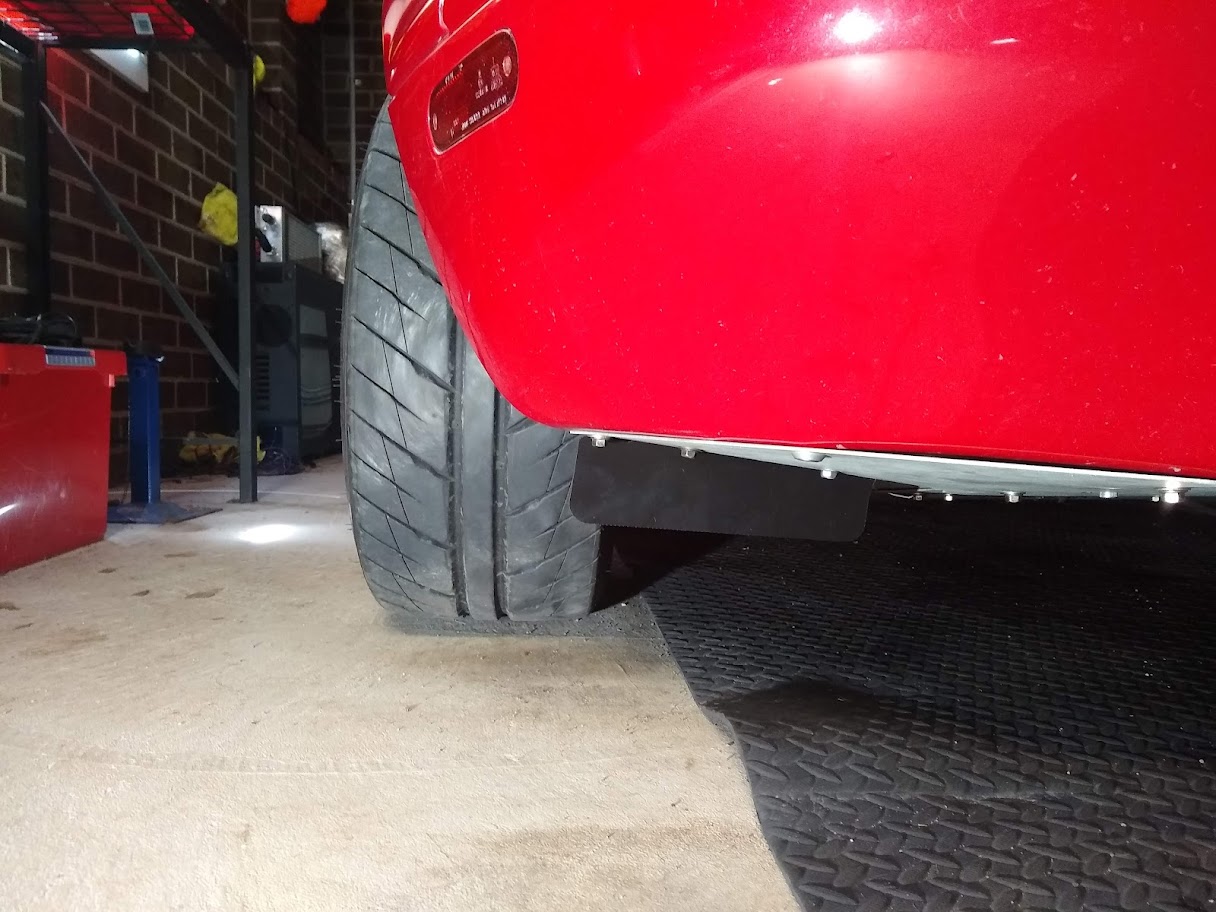
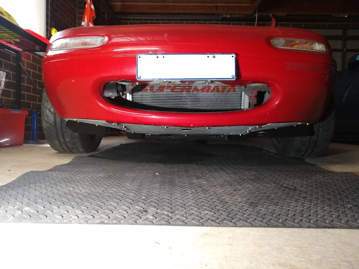
Also received and attempted to fit Honed Developments new brake air guides however there wasn't enough adjustment in the bracket to make it clear the undertray and the wheel at full lock. Gets pretty tight in there with 15x9 wheels and 225 tyres. Eventually I'll try and make a new bracket to package them a bit better.
Made a bit more progress on a little project I've been working on to replace the oil pressure gauge with a digital display in the instrument cluster. Since I removed the digital dash I wanted to add something to view a few different variables from the ECU but I didn't want to fit a gauge anywhere, plus all the available options are quite pricey. Was fun to make too
...yes it's upsidown...but you get the idea...
I used a little 1.28" round display connected through SPI to an Arduino to control it. It'll then receive CAN messages from the ECU to display the different signals with a push button (not sure where to place this yet) to change the displays. I also added some warnings for when some of the signals move past a threshold, as well as a check engine light mode. Still need to make a few changes to the code and design a PCB to mount the Arduino to the back of the cluster.
I've got it to the point where it'll fire up within about 0.5s but it immediately dies. Hopefully increasing the cranking throttle area demand will fix this.
I also thought it would be a good idea to check the fault action when disconnecting the electronic throttle. The initial settings I was using resulted in the engine speed shooting up to 2000rpm and bouncing there with a fuel cut limit. Not ideal since if you're in a low gear below that rpm and a there's an ETC fault then it would result in unintended acceleration.
So instead I set up another engine speed limit fault table specifically for ETC faults and limited the engine speed using pedal position. At 0% pedal the engine speed limit will be 1200rpm which will be much safer and shouldn't cause the car to accelerate forwad in the event of a fault. It's also set to increase the limit with pedal % so that the car should still be able to limp home, or at least to the side of the road.
In the event of a pedal position fault it'll revert to 0% so should be able to hold idle ok and creep in gear.
I ran out of things to 3D print and I was bored so I decided to make some tyre air deflectors for the front of the car. Idea is to direct the airflow around the tyres but not sure how well they'll work. Might try some back to back coast down tests but not sure if I'm going to see any difference.
Also received and attempted to fit Honed Developments new brake air guides however there wasn't enough adjustment in the bracket to make it clear the undertray and the wheel at full lock. Gets pretty tight in there with 15x9 wheels and 225 tyres. Eventually I'll try and make a new bracket to package them a bit better.
Made a bit more progress on a little project I've been working on to replace the oil pressure gauge with a digital display in the instrument cluster. Since I removed the digital dash I wanted to add something to view a few different variables from the ECU but I didn't want to fit a gauge anywhere, plus all the available options are quite pricey. Was fun to make too
...yes it's upsidown...but you get the idea...
I used a little 1.28" round display connected through SPI to an Arduino to control it. It'll then receive CAN messages from the ECU to display the different signals with a push button (not sure where to place this yet) to change the displays. I also added some warnings for when some of the signals move past a threshold, as well as a check engine light mode. Still need to make a few changes to the code and design a PCB to mount the Arduino to the back of the cluster.
Reply
1
1
11-06-2021, 06:19 PM
#80
Junior Member
Thread Starter
Join Date: Jun 2015
Location: VIC, Australia
Posts: 182
Total Cats: 58
Have finally taken the mx5 out on a few longer drives and I'm quite impressed with the Emtron. I did have an issue with the VVT not reading the full range which caused some odd behavior but I think I've fixed that up. Seems like I used the wrong VVT angle offset during my setup.
Still some work to be done on the pedal map as I'm not reaching pre-throttle pressure with the target throttle areas I've used (boost pressure signal is pressure just before the throttle). It feels quite nice in the lower areas though with a more progressive pedal than you would get with a cable throttle.
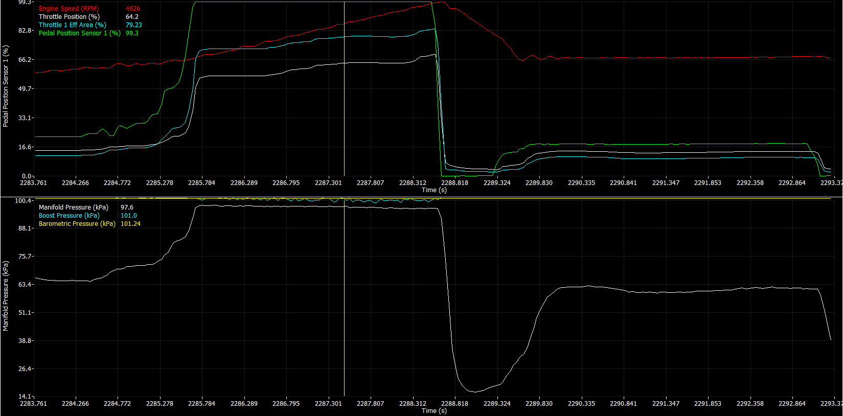
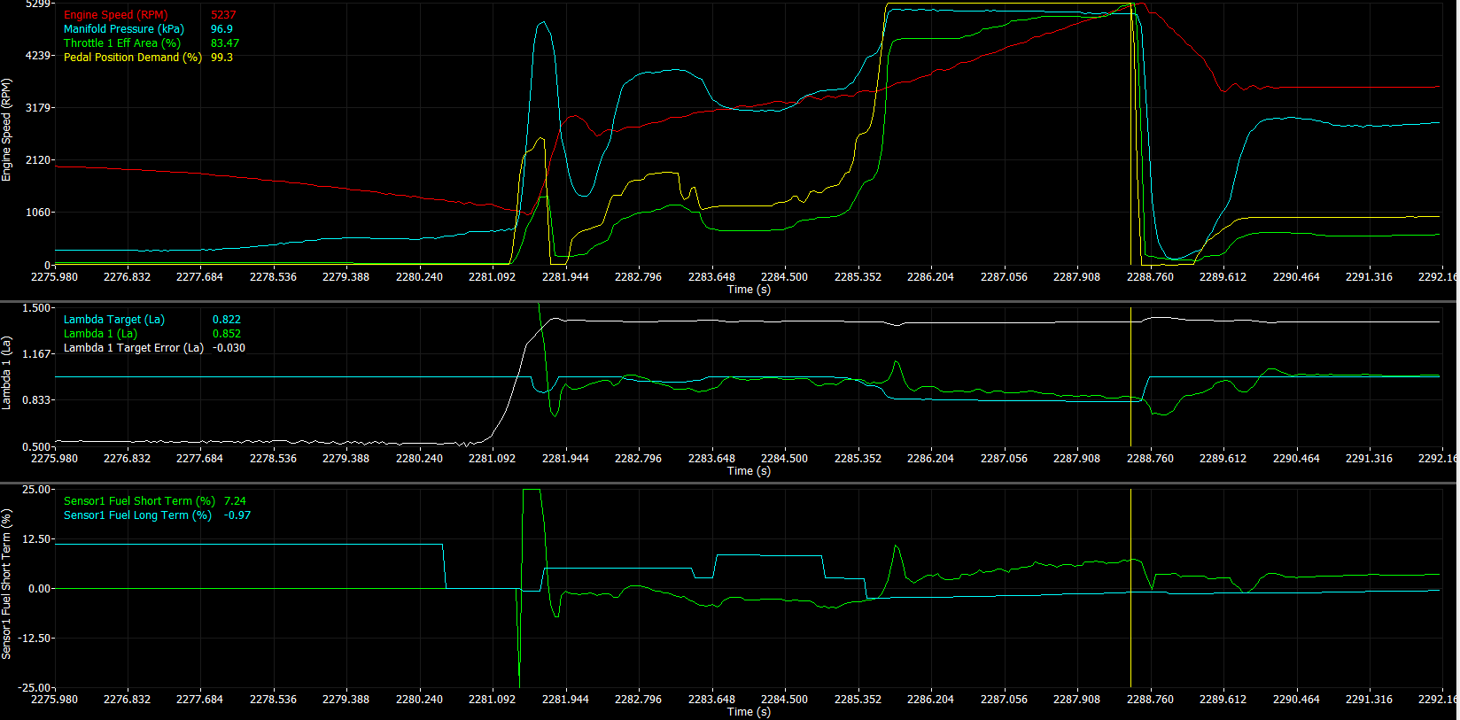
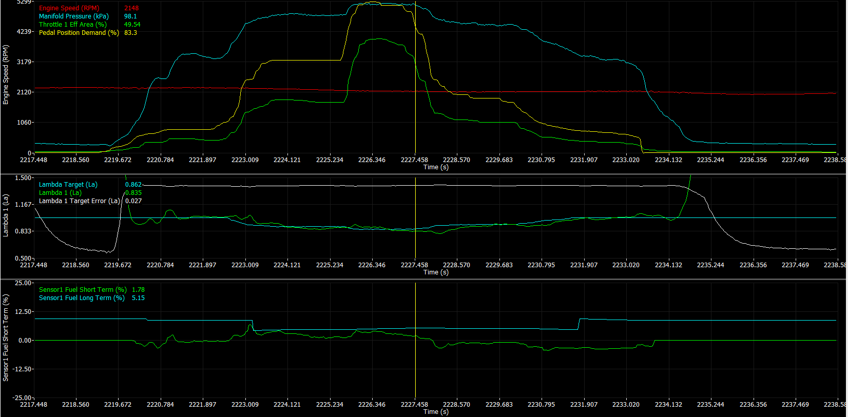
Drivability was also great. Just needed to make a few adjustments to fuel cut vehicle speed and engine speed thresholds but all the pedal transitions were really smooth. No acceleration enrichments needed either with the way the fuel algorithm works which is nice. Even with a lot of throttle movement the lambda stays quite close to target. A bit of adjustment to the MAF curve is still needed but it's not too far off and the throttle model is even closer.
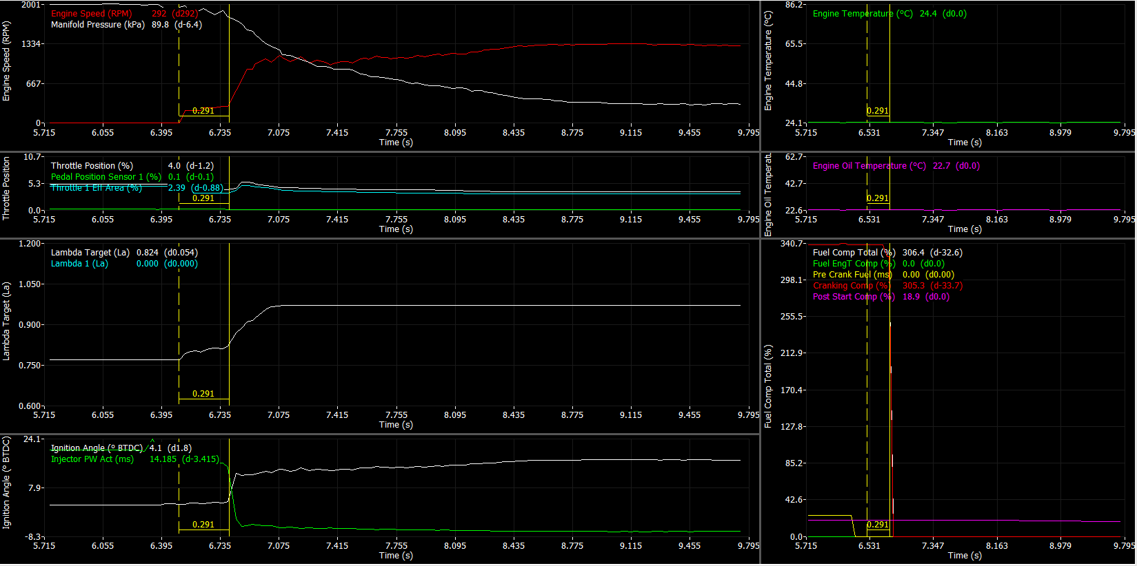
Cold starts, at least in the current weather are perfect too. Only ~0.3s to start from cranking.
Still some work to be done on the pedal map as I'm not reaching pre-throttle pressure with the target throttle areas I've used (boost pressure signal is pressure just before the throttle). It feels quite nice in the lower areas though with a more progressive pedal than you would get with a cable throttle.
Drivability was also great. Just needed to make a few adjustments to fuel cut vehicle speed and engine speed thresholds but all the pedal transitions were really smooth. No acceleration enrichments needed either with the way the fuel algorithm works which is nice. Even with a lot of throttle movement the lambda stays quite close to target. A bit of adjustment to the MAF curve is still needed but it's not too far off and the throttle model is even closer.
Cold starts, at least in the current weather are perfect too. Only ~0.3s to start from cranking.
Reply
1
1


