
BEAVIS' White NB Turbo Track Car


Junior Member
Joined: Jun 2015
Posts: 278
Total Cats: 22
Looking good!
Another DEI (or similar) product that aided my incabin temps drastically was some form of heat reflective shield along the tunnel and underside of the car (in addition to wrapping a majority of the exhaust, including downpipe). That significantly dropped cabin temps and all systems (including driver) were seemingly less taxed over the course of a trackday.
I think I ended up using an Inconel based product. At one point or another. It wasn;t cheap. However, with many a new car coming with such material, you could probably grab one off of one of the newer vehicles and cut it to spec.
Reply
 0
0

0

Thread Starter
Junior Member
Joined: Mar 2011
Posts: 212
Total Cats: 68
From: Melbourne, Australia
Looking good!
Another DEI (or similar) product that aided my incabin temps drastically was some form of heat reflective shield along the tunnel and underside of the car (in addition to wrapping a majority of the exhaust, including downpipe). That significantly dropped cabin temps and all systems (including driver) were seemingly less taxed over the course of a trackday.
I think I ended up using an Inconel based product. At one point or another. It wasn;t cheap. However, with many a new car coming with such material, you could probably grab one off of one of the newer vehicles and cut it to spec.
Another DEI (or similar) product that aided my incabin temps drastically was some form of heat reflective shield along the tunnel and underside of the car (in addition to wrapping a majority of the exhaust, including downpipe). That significantly dropped cabin temps and all systems (including driver) were seemingly less taxed over the course of a trackday.
I think I ended up using an Inconel based product. At one point or another. It wasn;t cheap. However, with many a new car coming with such material, you could probably grab one off of one of the newer vehicles and cut it to spec.
I had a look through my photos, but it appears I didn't take any photos of the stuff installed - pretty sure it was DEI brand.
I've run out of the DEI wrap and haven't done the downpipe..... I suppose it'd be worth getting more and wrapping that also?
Reply
0
0
Junior Member
Joined: Jun 2015
Posts: 278
Total Cats: 22
Yeah, I looked back through your pics to see if you did install something similar before I posted lol. And although it adds weight, fatigue and component reliability is high on my list of priorities and is something that is worth a few lbs IMHO. Just lay off the burritos and beer the night before if you are worried about lbs 
I tend to wrap anything that radiates a fair amount of heat (including downpipe). I essentially encapsulated a majority of my exhaust components and vented what was in the engine bay through louvers vents. The rest is ran underneath the car so airflow can take care of the rest.
I tend to wrap anything that radiates a fair amount of heat (including downpipe). I essentially encapsulated a majority of my exhaust components and vented what was in the engine bay through louvers vents. The rest is ran underneath the car so airflow can take care of the rest.
Reply
0
0
Thread Starter
Junior Member
Joined: Mar 2011
Posts: 212
Total Cats: 68
From: Melbourne, Australia
I'm not planning on having much trans tunnel airflow, due to a flat floor and ducted radiator.... so heat management will be important.
The next consideration is Diff and Trans coolers. I've not seen very much information specific to Miata's on the topic and google searches have only returned small amount of discussion on them.
So i'm going in a little blindly, but will see what I can come up with. I welcome any advice!
The next consideration is Diff and Trans coolers. I've not seen very much information specific to Miata's on the topic and google searches have only returned small amount of discussion on them.
So i'm going in a little blindly, but will see what I can come up with. I welcome any advice!
Reply
0
0

Thread Starter
Junior Member
Joined: Mar 2011
Posts: 212
Total Cats: 68
From: Melbourne, Australia
I have some people insisting that a naca duct under the transmission will be 'plenty' of airflow.
I'm not convinced.
I will, at the very least, be measuring the temperatures closely.
I'm not convinced.
I will, at the very least, be measuring the temperatures closely.
Reply
0
0
Thread Starter
Junior Member
Joined: Mar 2011
Posts: 212
Total Cats: 68
From: Melbourne, Australia
Reduced Mass Makes The Car Faster
Sorry it's been a while since the last update... but plenty of stuff has been happenning.
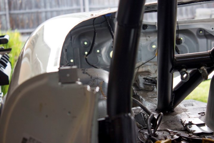
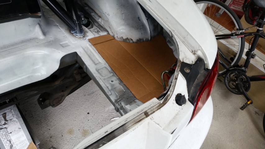
So following from my removal of the boot floor (to make room for the exhaust), I continued the work with the grinder and cut out the remainder of the boot floor, that being the parts either side of the main frame rails in the boot where the battery usually lives on these cars.
In theory I could probably cut the frame rails out also, however, I thought it would be good to keep them for now, at least until the wing mount is worked out.
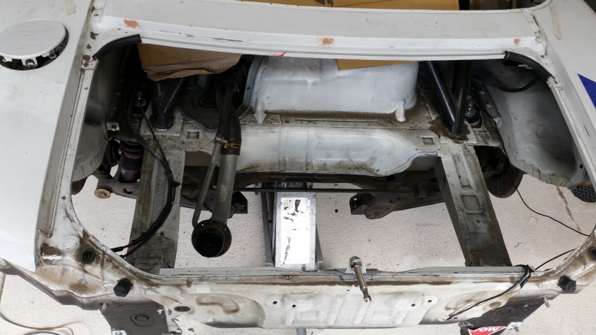
The other section I removed was the piece where the boot hinges usually bolt to, which lives between the passenger compartment and the boot area.
Not satsfied, I kept going with the grinder and took out the multiple layers of steel that lived above the rear wheel arches. There are about 4 layers of sheet metal here.
Sometimes it took a few passes with the grinder to take a layer off at a time to get the the next layer underneath.
And so many difficult hard to reach spots.
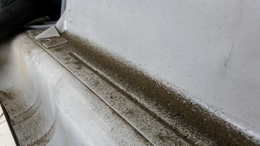
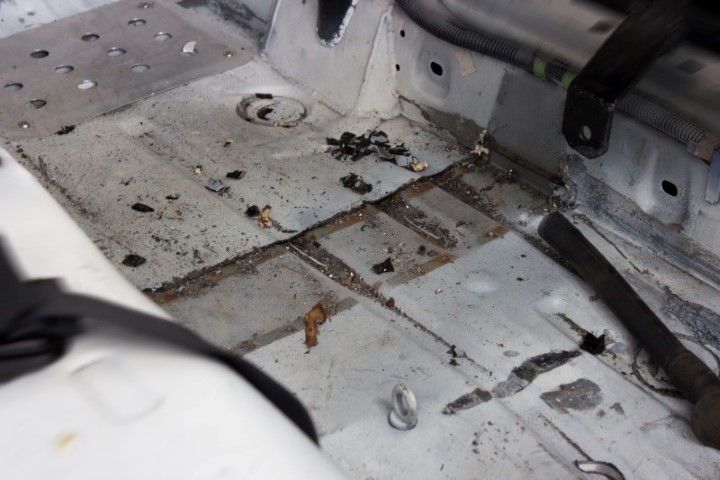
So much grinder dust and steel... and not looking forward to the cleaning that I will need to do.
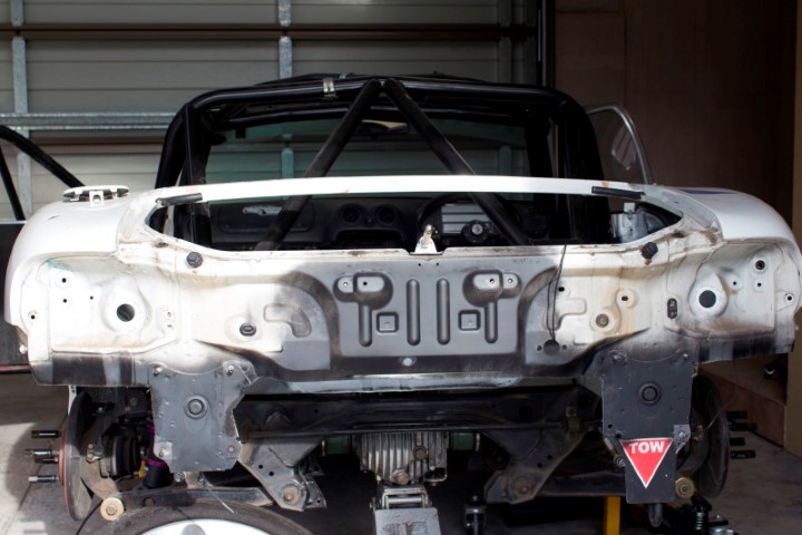
The car is so much more open now, and the rear so easily accessible from the cabin.
While all external metal is still in place, you can really see how much of an 'airy' feel it has now.
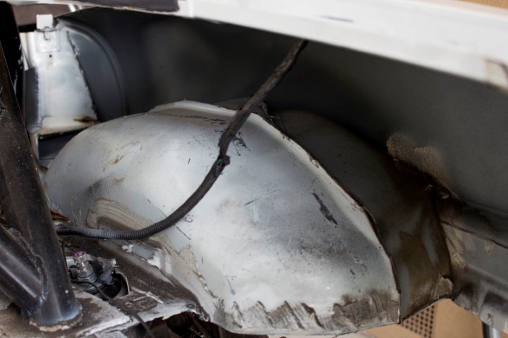
I just wish I could shrink the fuel tank hump down now as it seems like a big lump in the way of what could be a big flat area.... MX-5 ute perhaps?
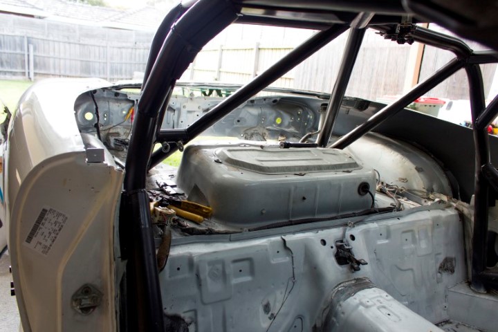
While I was on a roll, the seat mount hump thing on the drivers side of the car was drilled out and removed as the seat now bolts into the cage.
You can see the dash from the boot :P That's it for now....
Sorry it's been a while since the last update... but plenty of stuff has been happenning.
So following from my removal of the boot floor (to make room for the exhaust), I continued the work with the grinder and cut out the remainder of the boot floor, that being the parts either side of the main frame rails in the boot where the battery usually lives on these cars.
In theory I could probably cut the frame rails out also, however, I thought it would be good to keep them for now, at least until the wing mount is worked out.
The other section I removed was the piece where the boot hinges usually bolt to, which lives between the passenger compartment and the boot area.
Not satsfied, I kept going with the grinder and took out the multiple layers of steel that lived above the rear wheel arches. There are about 4 layers of sheet metal here.
Sometimes it took a few passes with the grinder to take a layer off at a time to get the the next layer underneath.
And so many difficult hard to reach spots.
So much grinder dust and steel... and not looking forward to the cleaning that I will need to do.
The car is so much more open now, and the rear so easily accessible from the cabin.
While all external metal is still in place, you can really see how much of an 'airy' feel it has now.
I just wish I could shrink the fuel tank hump down now as it seems like a big lump in the way of what could be a big flat area.... MX-5 ute perhaps?
While I was on a roll, the seat mount hump thing on the drivers side of the car was drilled out and removed as the seat now bolts into the cage.
You can see the dash from the boot :P That's it for now....
Reply
0
0
Thread Starter
Junior Member
Joined: Mar 2011
Posts: 212
Total Cats: 68
From: Melbourne, Australia
Sometimes I hate doing this stuff
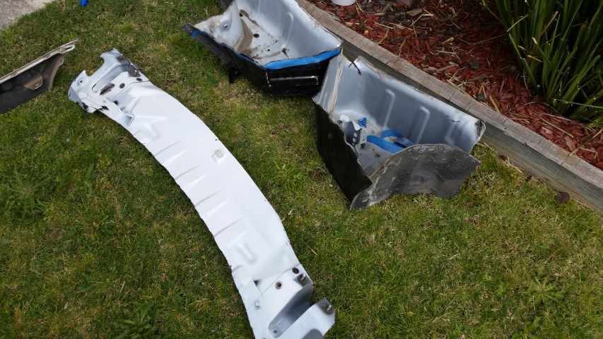
So some idiot cut a bunch of holes in my car and now I have to fill them back up.
So... bust out some CAD. I think the pictures say it all here.
The side sections need a slight kink about 3/4ths of the way along.
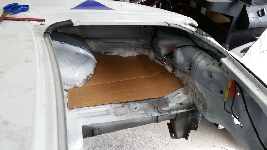
The sides will be mounted permanently, the middle section however will be bolted in for removal to make for easy access to... stuff?
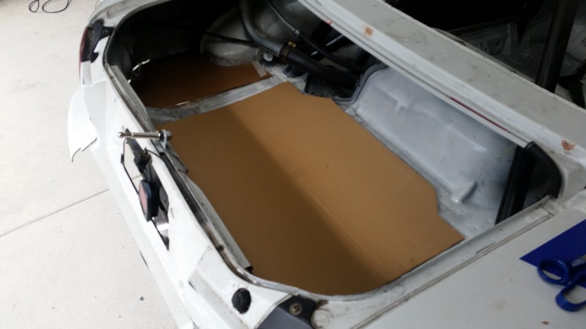
The middle section has a kick up at the rear to meet the rear of the boot.
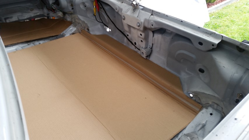
The carboard templates will be replaced with fibreglass panels weighing about 1/8th of the steel it replaces.
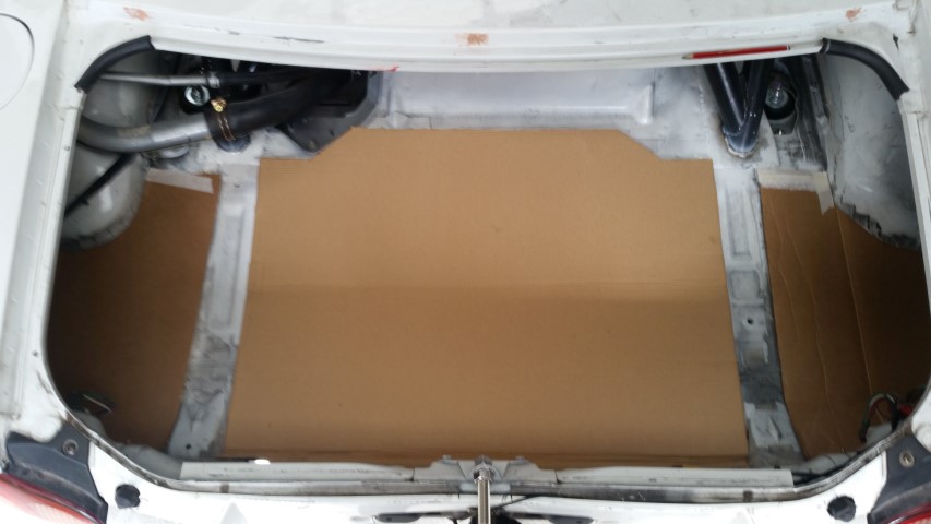
Oh by the way, take it from me, safety should always come first... my index finger had a close call with the grinder cutoff wheel because of the awkward cutting that was necessary.... so please always take care!
So some idiot cut a bunch of holes in my car and now I have to fill them back up.
So... bust out some CAD. I think the pictures say it all here.
The side sections need a slight kink about 3/4ths of the way along.
The sides will be mounted permanently, the middle section however will be bolted in for removal to make for easy access to... stuff?
The middle section has a kick up at the rear to meet the rear of the boot.
The carboard templates will be replaced with fibreglass panels weighing about 1/8th of the steel it replaces.
Oh by the way, take it from me, safety should always come first... my index finger had a close call with the grinder cutoff wheel because of the awkward cutting that was necessary.... so please always take care!
Reply
1
1


Thread Starter
Junior Member
Joined: Mar 2011
Posts: 212
Total Cats: 68
From: Melbourne, Australia
The middle section was about ~ 3.5kg / 7lbs.
I didn't weigh the side sections on the outer sides of the frame rails, but, I'd assume that together they're ~ 4kg / 9lbs
Then there was the metal under the rear quarterpanels, and the metal above the fuel tank, again, I didnt weigh it, but assume another 5kg / 11lbs or so.
Plus any of the other little superflous bits I could trim out.
All up, maybe 20kg / 45lbs all up? Not huge but it all helps.
Thanks!
Keep it slighty weatherproof
I didn't weigh the side sections on the outer sides of the frame rails, but, I'd assume that together they're ~ 4kg / 9lbs
Then there was the metal under the rear quarterpanels, and the metal above the fuel tank, again, I didnt weigh it, but assume another 5kg / 11lbs or so.
Plus any of the other little superflous bits I could trim out.
All up, maybe 20kg / 45lbs all up? Not huge but it all helps.
Reply
1
1
Thread Starter
Junior Member
Joined: Mar 2011
Posts: 212
Total Cats: 68
From: Melbourne, Australia
Intercoolers are cooler with proper tubing
Sorry for the delay between updates... I've got no excuse this time, just been otherwise occupied. But I've managed to do some things on the car...
Although I had already 'finished' the intercooler tubing, I wasn't happy with it.
The previous setup for the pipework from the Turbo to the Intercooler was 3 aluminium lengths joined by silicone 45deg bends.
This would result it too many potential failure points and too many heavy hose clamps.
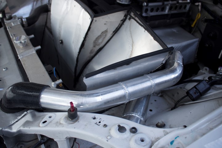
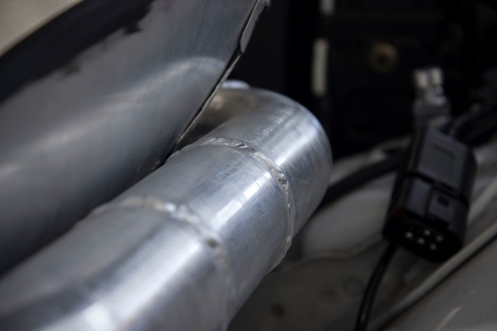
Thankfully the solution was simple, replace the silicone 45's with aluminium 45's. And now that I had the TIG welder, I could put this all together myself without too much trouble. (and any excuse for welding practice is good)
This is all 2" tube, to match the outlet from the turbo. The silicone joiner into the intercooler is a 2.5" to 2" reducer 90deg bend.
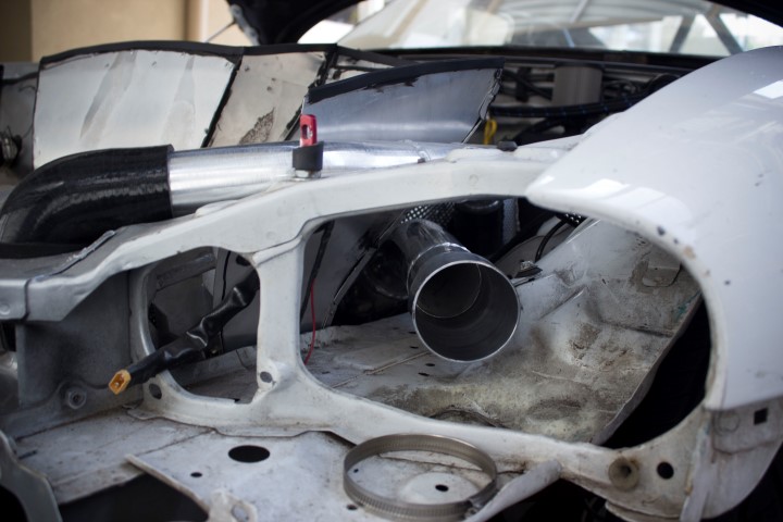
While I was at it, the intake INTO the turbo needed to be sorted out also as nothing had been done for that yet.
The tube work here is 2.5" to match the inlet to the turbo. Working backwards from the turbo to the pod filter there is a 90deg bend out and up from the turbo, and then another 90 to bring the tube parallel with the ground again and over the top of the frame rail. Then, a 3" to 2.5" reducer to adapt from the pod filter.
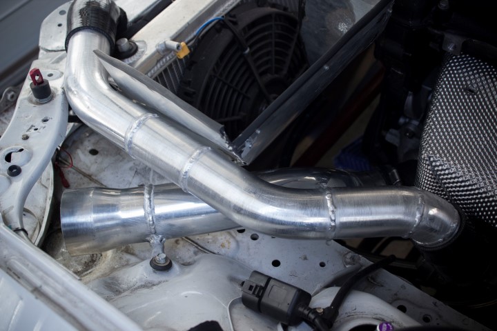
I decided to go with the pod filter mounted just behind the left hand headlight. (well, if I actually ran headlights) Theres plenty of room there for the pod, and any sort of intake ductwork or whatever I end up with here.... I do not have an exact plan for that yet.
Any thoughts on what I should do here exctly?
Box in the pod filter?
Naca duct in the headlight?
Or run some duct for some cold air intake into the pod perhaps?
Sorry for the delay between updates... I've got no excuse this time, just been otherwise occupied. But I've managed to do some things on the car...
Although I had already 'finished' the intercooler tubing, I wasn't happy with it.
The previous setup for the pipework from the Turbo to the Intercooler was 3 aluminium lengths joined by silicone 45deg bends.
This would result it too many potential failure points and too many heavy hose clamps.
Thankfully the solution was simple, replace the silicone 45's with aluminium 45's. And now that I had the TIG welder, I could put this all together myself without too much trouble. (and any excuse for welding practice is good)
This is all 2" tube, to match the outlet from the turbo. The silicone joiner into the intercooler is a 2.5" to 2" reducer 90deg bend.
While I was at it, the intake INTO the turbo needed to be sorted out also as nothing had been done for that yet.
The tube work here is 2.5" to match the inlet to the turbo. Working backwards from the turbo to the pod filter there is a 90deg bend out and up from the turbo, and then another 90 to bring the tube parallel with the ground again and over the top of the frame rail. Then, a 3" to 2.5" reducer to adapt from the pod filter.
I decided to go with the pod filter mounted just behind the left hand headlight. (well, if I actually ran headlights) Theres plenty of room there for the pod, and any sort of intake ductwork or whatever I end up with here.... I do not have an exact plan for that yet.
Any thoughts on what I should do here exctly?
Box in the pod filter?
Naca duct in the headlight?
Or run some duct for some cold air intake into the pod perhaps?
Reply
0
0

Thread Starter
Junior Member
Joined: Mar 2011
Posts: 212
Total Cats: 68
From: Melbourne, Australia
I'm actually considering just running a hose up from the radiator intake duct (i need to make up an alloy box) to a hole under where the pod will go, and boxing the pod in there.
Thanks

Reply
0
0
Junior Member
Joined: Jun 2015
Posts: 278
Total Cats: 22
Very simple method. Just add a pressure gauge to another port to watch for pressure drop. Or, you can add another port to introduce smoke (smoke in a can works great).
https://www.volvoclub.org.uk/faq/Spe...PressureTester
https://www.volvoclub.org.uk/faq/Spe...PressureTester
Reply
0
0

Junior Member
Joined: Mar 2013
Posts: 209
Total Cats: 35
Very simple method. Just add a pressure gauge to another port to watch for pressure drop. Or, you can add another port to introduce smoke (smoke in a can works great).
https://www.volvoclub.org.uk/faq/Spe...PressureTester
https://www.volvoclub.org.uk/faq/Spe...PressureTester
Reply
0
0


