
f20c engine conversion


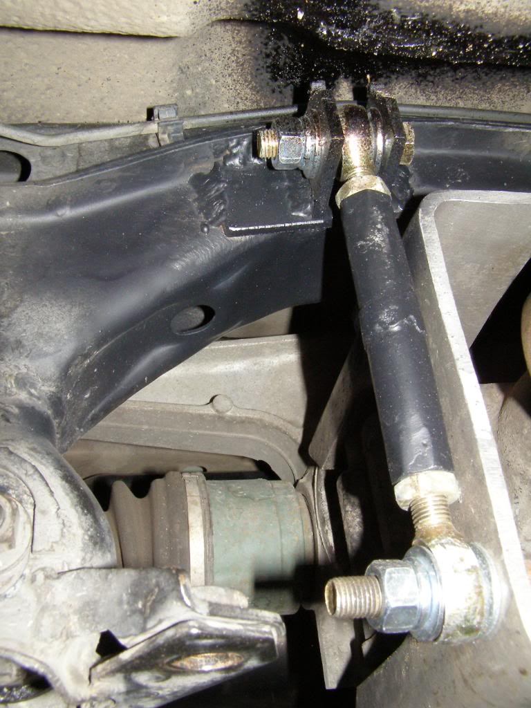
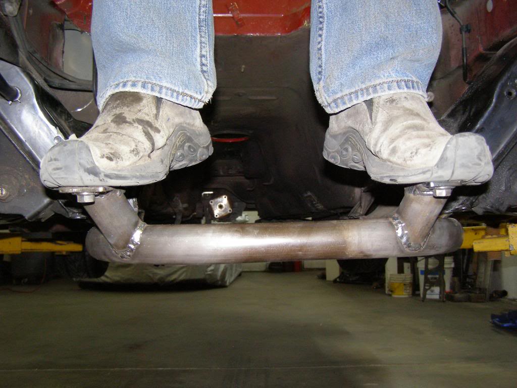
I am guessing that many of you may be wondering what I did to keep the differential located since I no longer have the PPF. Pictures speak a thousand words, so here are a couple of pictures. Simple and sweet, I like the KISS principle!

Last edited by hingstonwm; Jan 31, 2010 at 08:18 PM.
Reply
 0
0

0

Junior Member
Joined: Jan 2010
Posts: 92
Total Cats: 0
From: Eastside Muff~Palmdale,CA
F20C turbo is a route I wish to go in the future.Overall nice build up,keep up the progress!! I think you have the best Rack mount by far..
-Is the rearend basically solid mounted without any bushings?(maybe i missed seeing them)
-Is the rearend basically solid mounted without any bushings?(maybe i missed seeing them)
Reply
0
0


Thanks for the props guys!!
Eadohcturbo, I actually sleeved the subframe and bolted the rubber into place. The thought process is that the rubber will help isolate any harmonics that might be present. The set up is quite as stock. I am using factory diff mounts located at the end of the diff arms. The nut holding the rubber in place is a jet nut, I actually used this to adjust the pinion angle then the "end link" to hold everything in place.
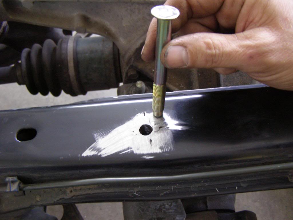
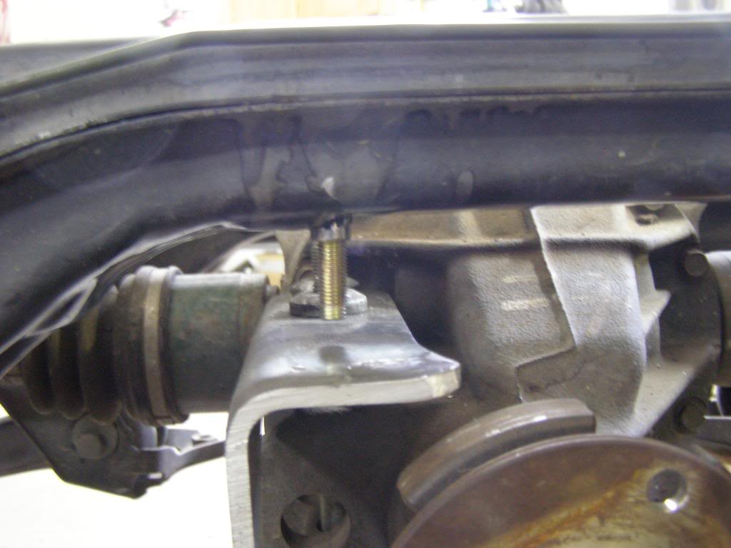
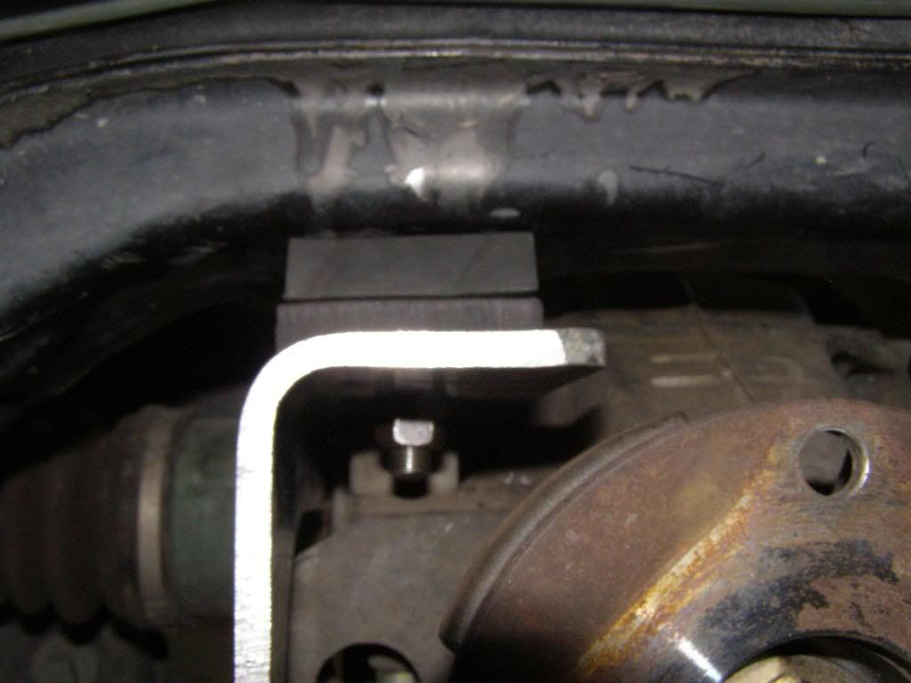
Eadohcturbo, I actually sleeved the subframe and bolted the rubber into place. The thought process is that the rubber will help isolate any harmonics that might be present. The set up is quite as stock. I am using factory diff mounts located at the end of the diff arms. The nut holding the rubber in place is a jet nut, I actually used this to adjust the pinion angle then the "end link" to hold everything in place.
Reply
0
0


Reply
0
0
I have not been crazy about the location of the honda under hood fuse box, and I was concerned about the engine wiring harness being routed right where the down pipe is going to live. Not to mention the power wire for the starter.The solution was to move the fuse box to under the dash. I was also able to get rid of the miata under hood fuse box. I isolated the wires for the headlights and the retractors and installed inline fuses the result is a clean engine bay. I will still need to reroute the brake line, but I will wait until I have the turbo mocked up so I know exactly where everything lives.
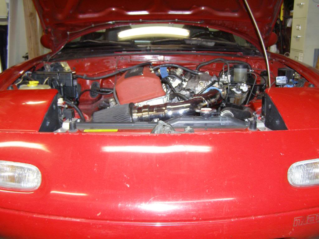
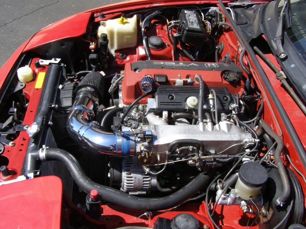
The engine harness is the wire loom that can be seen just to the left of the valve cover with the rubber grommet going through the fire wall.
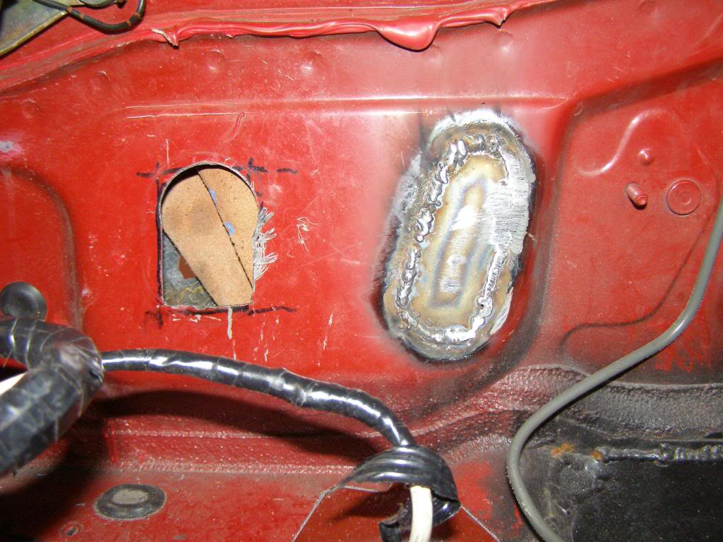
I had to remove the dash, blower motor assembly and the cross over tube to have good access to make sure i didn't catch the sound proofing material on fire when welding up the holes. To make the patches i covered the holes with tape then cut the tape out and transferred the pattern to steel.
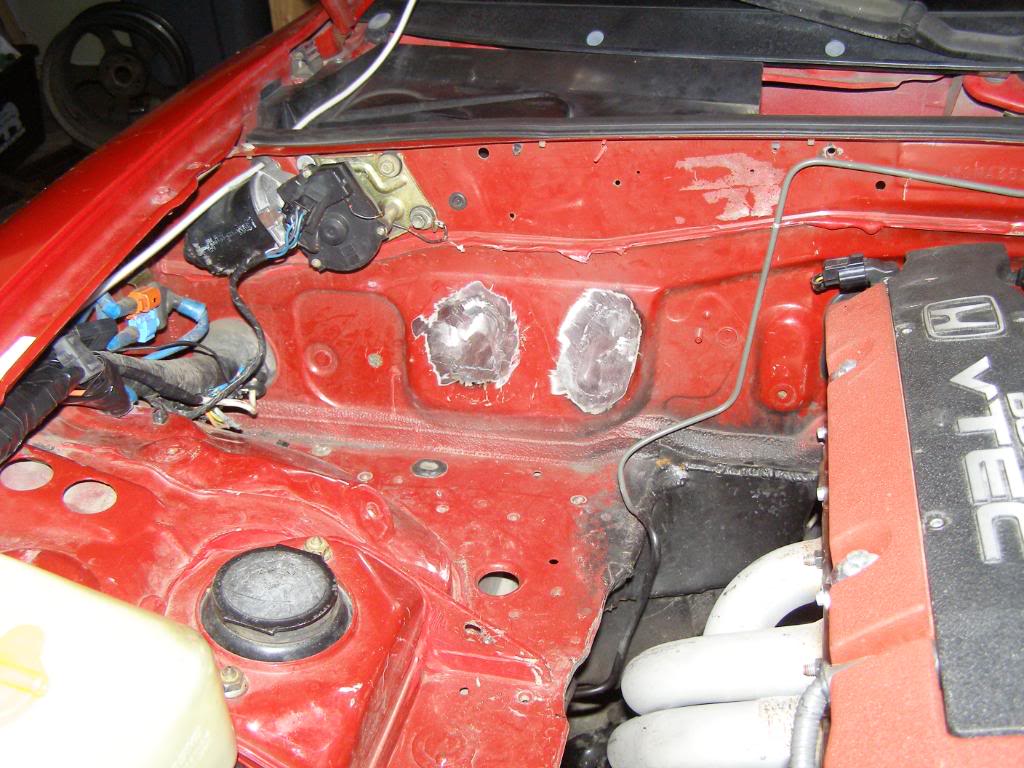
Happy with the results! I will prime it to keep away the rust. I plan on painting the engine compartment next winter.
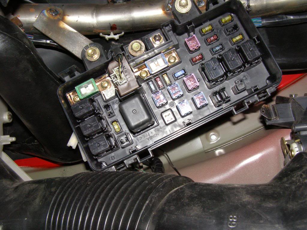
Here is the new home for the fuse box. I was able to to keep the heater and cross over tube, a must for a street car
The engine harness is the wire loom that can be seen just to the left of the valve cover with the rubber grommet going through the fire wall.
I had to remove the dash, blower motor assembly and the cross over tube to have good access to make sure i didn't catch the sound proofing material on fire when welding up the holes. To make the patches i covered the holes with tape then cut the tape out and transferred the pattern to steel.
Happy with the results! I will prime it to keep away the rust. I plan on painting the engine compartment next winter.
Here is the new home for the fuse box. I was able to to keep the heater and cross over tube, a must for a street car
Last edited by hingstonwm; Feb 9, 2010 at 12:43 PM.
Reply
0
0

Sorry for the long post but it takes time to describe wiring. Anyone know a good electrical guy? Actually it is not as bad as it looks. The stock ECM has an immobilizer feature that won’t allow the fuel pump to run unless the corresponding chipped key is linked. I like this anti theft feature and wanted it in place while the car was a DD.
Getting the engine to run was not all that complicated, I took an entire s2000 wiring harness (sourced from different cars) and connected everything. The under hood fuse box acts as the distribution point for power, so all I needed to do was get power from the Miata battery to the Honda fuse box and also get power to the Miata fuel pump through the Honda harness. I used the stock positive cable from the Miata to do this, I ground down the stock Miata connector that usually hooks to the starter post until it would fit the connection on the fuse box. I will address the fuel pump in another post.
With the Honda side of the equation addressed, I needed to get power to the Miata side of things. To do this I pinned out the Miata ignition switch and the Honda switch. On the Honda switch I needed to know which post was accessory position and which was run position. On the Miata switch I needed to identify run position, after dong this I used heavy gauge wire and connected the Honda switch to the Mazda switch; Honda run and accessory post to Mazda run post. The Miata switch is left in the run position and is nothing more than a connection now. I zip tied the switch with key under the dash. The electrical flow is simple, turn the Honda ignition switch and power flows through the Honda system normally, while the Mazda (rest of the car with the exception of the fuel pump) is powered through the jump wires coming of the accessory post and run post on the Honda ignition switch.
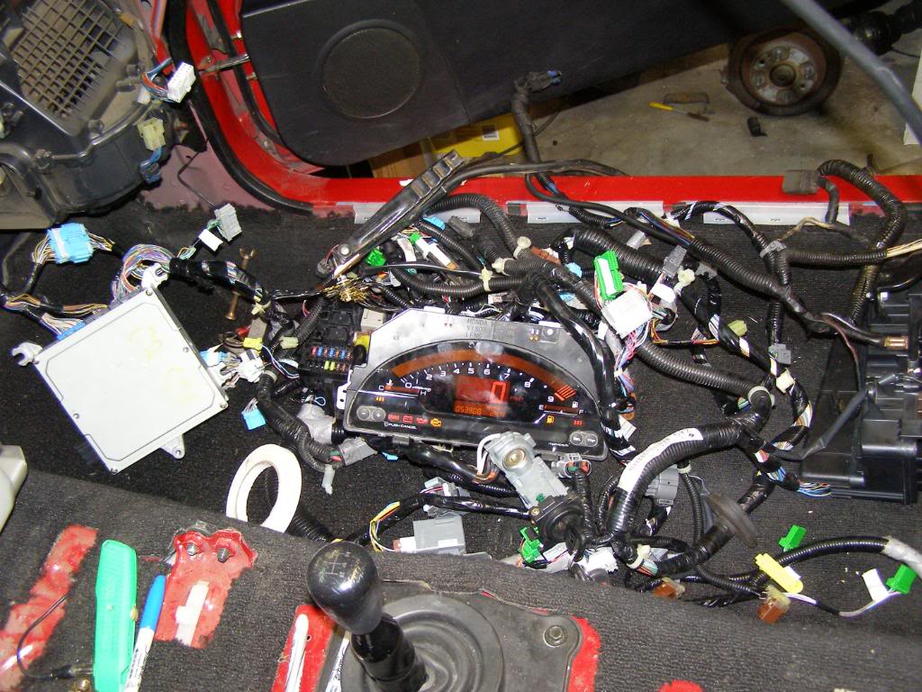
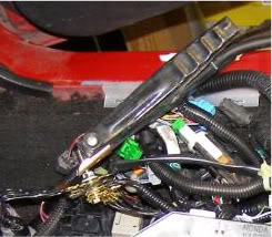
In my opinion it is easier to get an engine swap running with the donor harness exposed then figure out how to tidy it up and tuck it away within the car. I used the passenger floor board as my work space. I located all of the ground wires in the Honda harness, then, using a long bolt connected them all together. To get power to this mess, I hooked the battery up which energized the positive side of the system and used jumper cables hooked from the negative terminal of the battery to the bolt with all the ground wires on the Honda wiring harness. Power to the starter comes off the Honda fuse box, since the fuse box was on the floor of the car, the starter wire would not reach. The temporary solution was to use a second battery cable running from the fuse box side of the starter cable to the fuse box. I clamped the two ends together with a pair of vice grips, crude yes, but it allowed for a quick disconnect should there be a problem while sorting out the wiring. I considered the system “up and running” when I had crank but no start.
Once I had crank but no start I loaded the car up and headed to the Acura dealer in Colorado Springs; I had a connection there that was going to get an immobilizer code for me from Honda. Once we had the immobilizer code Paul hooked up the several thousand dollar Honda diagnostic computer to my system through the OBD2 port, entered the code, jumped through hoops, cycled the key, punched in more codes, prayed to the immobilizer gods and declared the operation complete. All that was left to do was try and start the car. Humana humuna humana VAAAAROOOOOM….yeah it’s running…..okay turn it off that open header is really really loud!!!!
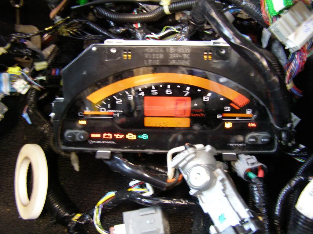
In this shot you will notice that the green key is not illuminated on the instrument cluster, this is after the immobilization code was input and the engine would run.
Here are all the grounds bolted together and the negative jumper cable attached to the bolt.
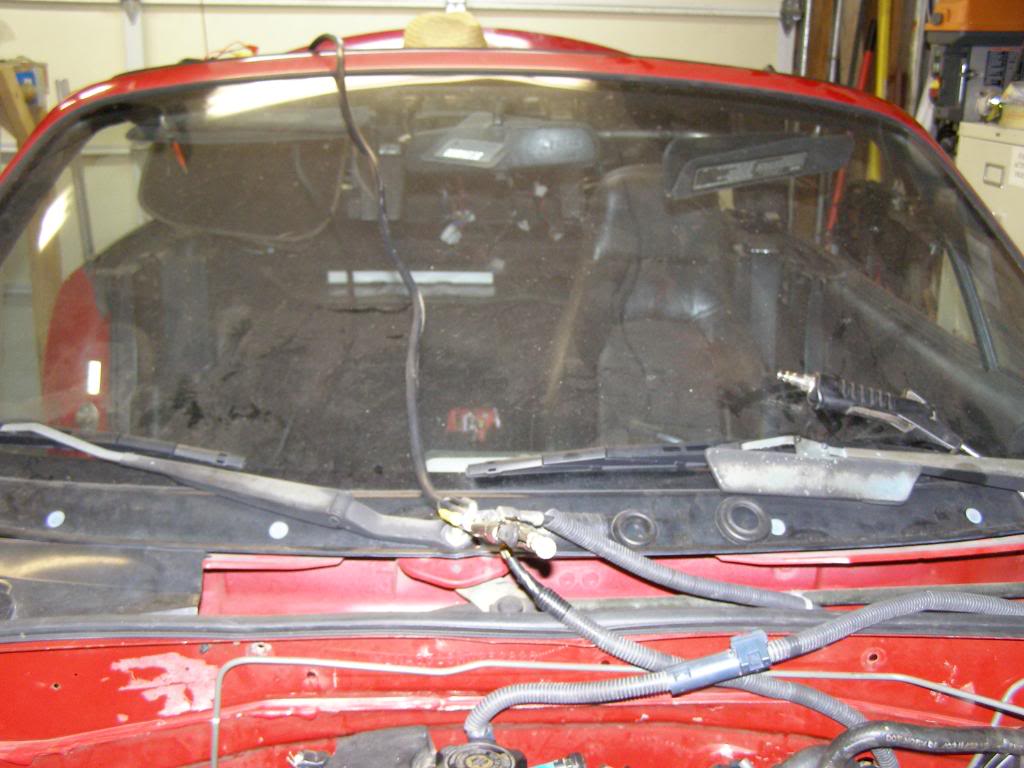
Starter power supply and extension going over the windshield and down to the fuse box, look closely and you can see the vice grips holding them together.
Getting the engine to run was not all that complicated, I took an entire s2000 wiring harness (sourced from different cars) and connected everything. The under hood fuse box acts as the distribution point for power, so all I needed to do was get power from the Miata battery to the Honda fuse box and also get power to the Miata fuel pump through the Honda harness. I used the stock positive cable from the Miata to do this, I ground down the stock Miata connector that usually hooks to the starter post until it would fit the connection on the fuse box. I will address the fuel pump in another post.
With the Honda side of the equation addressed, I needed to get power to the Miata side of things. To do this I pinned out the Miata ignition switch and the Honda switch. On the Honda switch I needed to know which post was accessory position and which was run position. On the Miata switch I needed to identify run position, after dong this I used heavy gauge wire and connected the Honda switch to the Mazda switch; Honda run and accessory post to Mazda run post. The Miata switch is left in the run position and is nothing more than a connection now. I zip tied the switch with key under the dash. The electrical flow is simple, turn the Honda ignition switch and power flows through the Honda system normally, while the Mazda (rest of the car with the exception of the fuel pump) is powered through the jump wires coming of the accessory post and run post on the Honda ignition switch.
In my opinion it is easier to get an engine swap running with the donor harness exposed then figure out how to tidy it up and tuck it away within the car. I used the passenger floor board as my work space. I located all of the ground wires in the Honda harness, then, using a long bolt connected them all together. To get power to this mess, I hooked the battery up which energized the positive side of the system and used jumper cables hooked from the negative terminal of the battery to the bolt with all the ground wires on the Honda wiring harness. Power to the starter comes off the Honda fuse box, since the fuse box was on the floor of the car, the starter wire would not reach. The temporary solution was to use a second battery cable running from the fuse box side of the starter cable to the fuse box. I clamped the two ends together with a pair of vice grips, crude yes, but it allowed for a quick disconnect should there be a problem while sorting out the wiring. I considered the system “up and running” when I had crank but no start.
Once I had crank but no start I loaded the car up and headed to the Acura dealer in Colorado Springs; I had a connection there that was going to get an immobilizer code for me from Honda. Once we had the immobilizer code Paul hooked up the several thousand dollar Honda diagnostic computer to my system through the OBD2 port, entered the code, jumped through hoops, cycled the key, punched in more codes, prayed to the immobilizer gods and declared the operation complete. All that was left to do was try and start the car. Humana humuna humana VAAAAROOOOOM….yeah it’s running…..okay turn it off that open header is really really loud!!!!
In this shot you will notice that the green key is not illuminated on the instrument cluster, this is after the immobilization code was input and the engine would run.
Here are all the grounds bolted together and the negative jumper cable attached to the bolt.
Starter power supply and extension going over the windshield and down to the fuse box, look closely and you can see the vice grips holding them together.
Last edited by hingstonwm; Feb 15, 2010 at 12:17 AM.
Reply
0
0
This car has been a lot of fun. If you keep your foot out of it you can get 35mpg...not to bad for a car that will go 0-60 in 5 flat!
Last edited by hingstonwm; Feb 9, 2010 at 07:20 PM.
Reply
0
0

Junior Member
Joined: Dec 2009
Posts: 332
Total Cats: 1
From: Shelbina, MO (North East)
I love the picture of the electrical work. I've been there. Built my own factory style harness for another project car I had. Mine was very simple compared to a new Honda, but I did cut up a factory harness for supplies.
Reply
0
0
Yeah you gotta love electrical work. I was able to get rid of most of the harness as it ran more than the engine. I did have to save some of the harness to run the instrument cluster, fuel pump, and sending unit. I found a great Honda electrical service manual that helped me sort through all the wiring.
Reply
0
0
I got around to installing my new/used manual rack this weekend. Although I like the quicker ratio of the power rack it is bulky when compared to the manual rack. The installation was not a simple part swap. I wanted to take advantage of the smaller size of the manual rack and snuggle it up as close to the engine as safely possible. To do this I needed to remove the old mounting legs and fabricate some new ones to accommodate the new rack and mounting position. This was a much harder fab since it took place with the engine in the car.
My original mount notice how tall the legs are and how far forward they are in relation to the tube frame
Mocking up the original rack mount
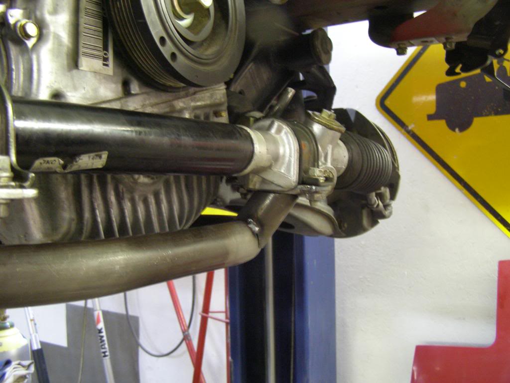
Original installation of the power rack. Note large diameter of rack and forward location in comparison to the tube frame
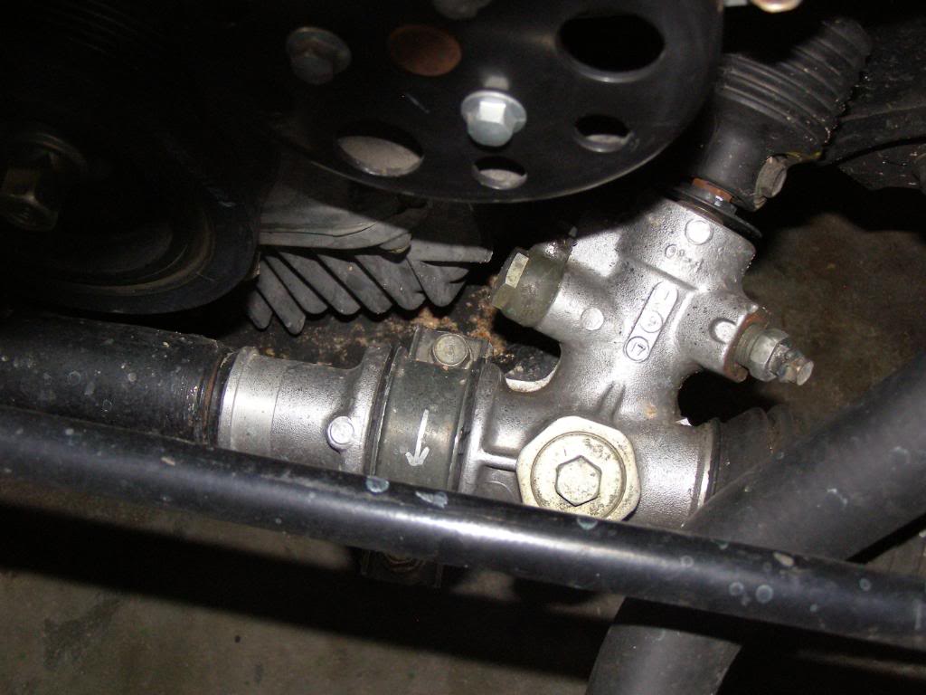
Original rack mount with power rack, note mounting plate forward of the engine sump
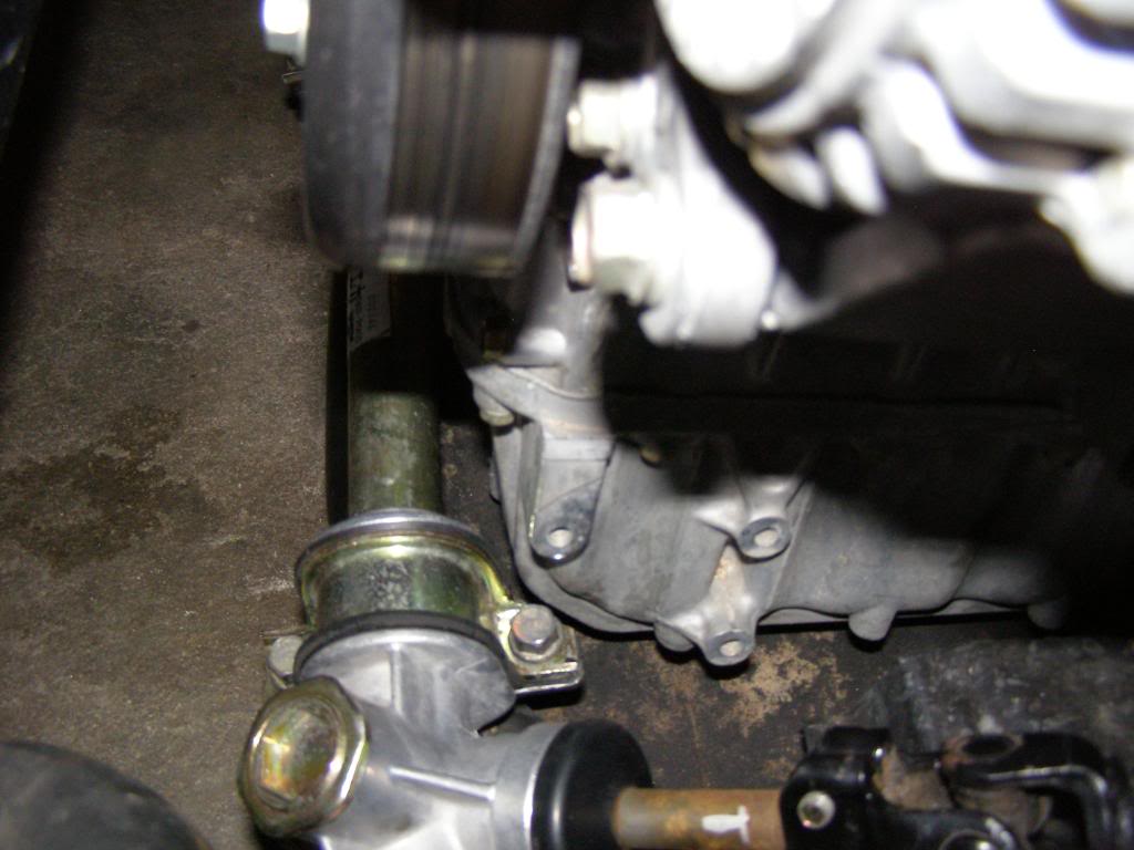
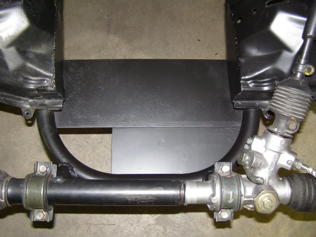
Completed install of the manual rack, I offset the rack slightly to the right to gain extra clearance then trimmed the bracket. Note the position of the mounting bracket is now behind the front of the engine sump and how thin the manual rack is compared to the power rack
Rack is back as far as I dare, it is tight but there is clearance.
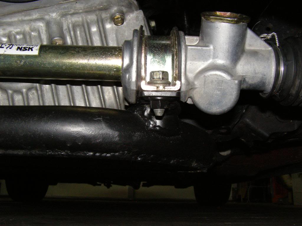
Compared to the original mounting stubs this is substantially shorter

Compared to the original mounting stubs this is substantially shorter
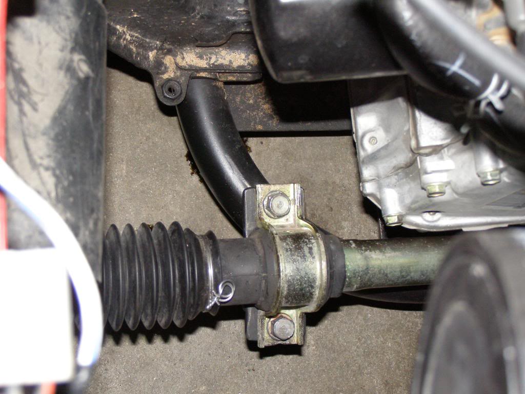
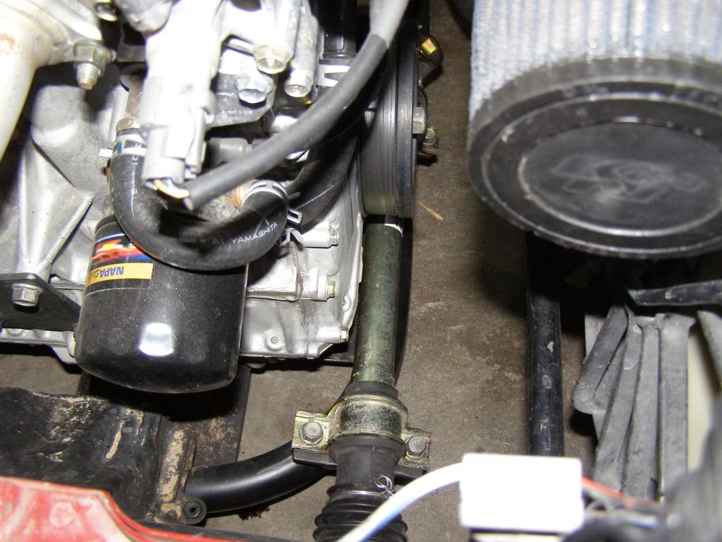
Look at the relation of the rack to the tube frame; you can see tube frame in front of the rack, I managed to move the rack backwards about 2 inches. Moving the rack made the car easier to steer at lock as the inner knuckles of the tie rod do not approach bind. It also reduced the the angle of the tie rods and moved the tie rods to an opposite angle of the factory setting, meaning that the car steers as stock.
My original mount notice how tall the legs are and how far forward they are in relation to the tube frame
Mocking up the original rack mount
Original installation of the power rack. Note large diameter of rack and forward location in comparison to the tube frame
Original rack mount with power rack, note mounting plate forward of the engine sump
Completed install of the manual rack, I offset the rack slightly to the right to gain extra clearance then trimmed the bracket. Note the position of the mounting bracket is now behind the front of the engine sump and how thin the manual rack is compared to the power rack
Rack is back as far as I dare, it is tight but there is clearance.
Compared to the original mounting stubs this is substantially shorter
Compared to the original mounting stubs this is substantially shorter
Look at the relation of the rack to the tube frame; you can see tube frame in front of the rack, I managed to move the rack backwards about 2 inches. Moving the rack made the car easier to steer at lock as the inner knuckles of the tie rod do not approach bind. It also reduced the the angle of the tie rods and moved the tie rods to an opposite angle of the factory setting, meaning that the car steers as stock.
Last edited by hingstonwm; Feb 15, 2010 at 11:08 AM.
Reply
0
0

I haven't had a chance to get it out on the track since the change, I will be interested to see if there is a difference in feedback through the wheel.
I believe that I have optimized bump steer as well. My tie rods are at opposite angle from stock, so bump steer should act as factory.
Reply
0
0


