When you click on links to various merchants on this site and make a purchase, this can result in this site earning a commission. Affiliate programs and affiliations include, but are not limited to, the eBay Partner Network.
- Replaced factory narrow band O2 with my ancient LC1
- Installed MS2E. Started right up and idled fine
- Installed ID725's. Had to rewire the injector plugs.
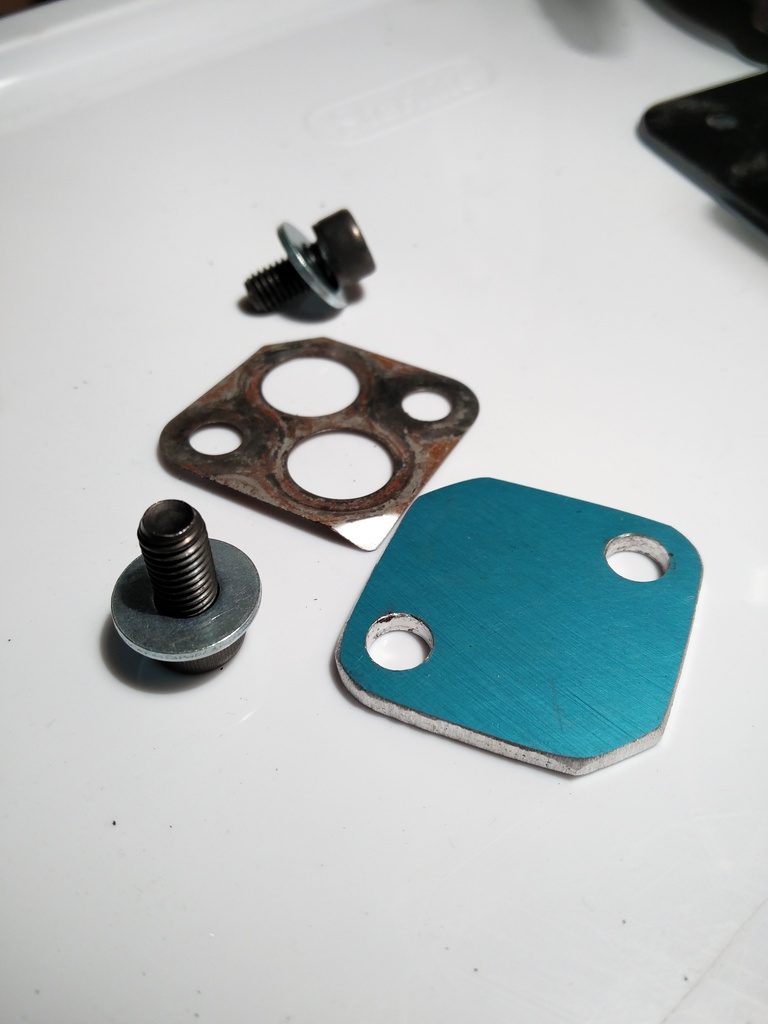
I left the EGR valve off so I could make a block off plate as I already have the EX manifold plug blocked and a plate where the other side of the EGR pipe connects to the IM. I wasn't really thinking about the fact that this means I now have a 1/2" hole right into my IM plenum...
I adjusted req fuel to match the ID's cc's, and it started right up, all the way up to 3k rpm or so
I'll make the block off plate later this week and if it's sunny out, do some VEAL tuning.
I need to start thinking about all the turbo plumbing.
Oil drain fitting in pan: Should be easy, yay MSM block.
I don't really want to buy this Adapter Plate as it's expensive and looks kinda cheap. So I'll likely make my own.
Oil drain line: -10AN braided line and AN fittings at each end. I should probably replace the adapter plate on the turbo as it looks like it's seen better days.
Oil feed line: I need to get an adapter fitting for the block feed hole and inspect the turbo more carefully to see if it already has a restrictor.
Water feed/return: The msm uses a nipple on the heater core cross over pipe, but I replaced that whole assembly with a 99/00 crossover pipe, so I guess I'll just tap the mixing manifold and use the block water fitting. Need to find a banjo bolt and adapter for the block side.
Down pipe: One of these, some of this, and one of these.
Hot side piping/intercooler:I have a BEGI upgrade intercooler left over from my NA, but it seems really silly to use something that has mounts welded on to it for baby teeth when I don't have baby teeth and I have a metric **** ton of space in the nose for an intercooler. Maybe make my own using this stuff? Plus welded aluminum piping for plumbing.
Cold side piping/Air filter: Even with a monster intercooler there's still a bunch of room in the nose for a cold air intake. Also with no fender wells there is plenty of room to route the piping. So more welded aluminum piping and a giant air filter.
BOV: I've got an old bosch recirc valve that I could put somewhere and route back to the intake. Or get some ridiculously loud one?
Am I missing anything? I guess some kind of boost control?
Am I missing anything? I guess some kind of boost control?
Double-acting wastegate can and a 4-port solenoid.
FWIW, I really like the FM hard lines for the turbo coolant. They probably don't fit with the TSE manifold location, but after putting them on my engine bay no longer smells faintly of coolant after driving the car, for the first time in a decade.
Where do you have the intake air temp sensor mounted?
Oil drain line: I should probably replace the adapter plate on the turbo as it looks like it's seen better days.
I have 3 of these in the garage, I'll get them over to you.
Originally Posted by gesso
Oil feed line: I need to get an adapter fitting for the block feed hole and inspect the turbo more carefully to see if it already has a restrictor.
My sweet *** stainless braid black sheathed teflon lined oil feed line with the swaged ends came from BAT-INC. I picked the ends, length, hose and color and they charged me $3 to assemble it. It makes me feel better that someone who knew what they were doing and had the proper tools assembled it for me.
Originally Posted by gesso
Water feed/return: The msm uses a nipple on the heater core cross over pipe, but I replaced that whole assembly with a 99/00 crossover pipe, so I guess I'll just tap the mixing manifold and use the block water fitting. Need to find a banjo bolt and adapter for the block side.
I still have the drills, taps and some extra -6 to metric threaded fittings we used on my mixing manifold, if you want to go that route. I thought it came out pretty well. Of course, you could probably just weld a bung and tap a nipple on the back/top of the mixing manifold, its not like you have a bunch of hardware under the hood you need to clear.
Originally Posted by gesso
Cold side piping/Air filter: Even with a monster intercooler there's still a bunch of room in the nose for a cold air intake. Also with no fender wells there is plenty of room to route the piping. So more welded aluminum piping and a giant air filter.
I've got both the big Amsoil and the ProDry sitting in the garage, they both still need homes.
Originally Posted by gesso
BOV: I've got an old bosch recirc valve that I could put somewhere and route back to the intake. Or get some ridiculously loud one?
I vote recirc. Its slightly harder to plumb in initially but you wont have filtration issues from the valve leaking at idle. Also, if you use that tiny turbo I feel like you are going to be venting a lot of boost pretty regularly and the noise is going to get tiresome.
Plus, you know who makes a fabulous recirculating valve to replace that Bosch pattern one? TurboSmart. You can pick them up used in great shape under $100 pretty frequently.
Originally Posted by gesso
Am I missing anything? I guess some kind of boost control?
Originally Posted by codrus
Double-acting wastegate can and a 4-port solenoid.
If he is going to run the GT2554R on that manifold with that exhaust, I feel like the wastegate staying shut is going to be the least of his worries
Originally Posted by codrus
Intake catch cans?
Oo, this ^^ In for magical Gesso catch can fabrication pics. I've always wanted to cut up an old MSR fuel bottle and build a catch can out of it.
The grooved ones have less room for error because they won't even mate if you warp them too much. Didn't think you would have trouble with them, just a heads up.
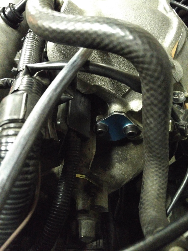
I made an egr block off plate some time earlier this week.
And installed it this evening.
With req fuel adjusted for the 725's (4.3) the car started but would die as soon as CL idle kicked in. I turned off CL idle and let it warm up at ~550 rpm and then added fuel untill it ran well at idle, but I had to add waaaaay more than expected (+18 points in my ve table). I adjusted req fuel to 4.9 (simulating 625cc) and it was better but still much too lean. I'll poke more tomorrow, but I suspect I'm either not understanding something or something is wrong with the injectors(they were used)...
Last edited by gesso; Feb 6, 2016 at 01:06 AM.
Reason: Fixed pics
I made some mounts for the MS2 this afternoon. Aluminum angle brackets held to case by the endcap mount screws, old fuel system rubber isolators, and rivnuts into the transmission tunnel.
I then spent some time adjusting the ve table to deal with the new injectors. Got it where it seems pretty happy. And then I decided I would get the LC1 to connect via CANBus.
After a fair bit of trials and tribulations (mostly due to my lack of knowledge ) I got the system set up as follows:
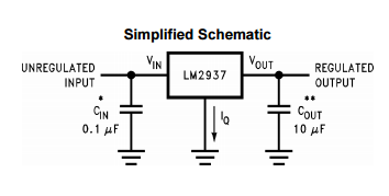
I had some issues powering the tinyio. Apparently it draws too much current to be run off the MS vref (not surprising really). So I ended building a 5v regulator with a LM2937-5 and a few caps in the proto area of the tinyio. I fed this 12v from the fused 12v output on the DB37 (the LC1 is powered from the old radio circuit as there is no radio anymore).
It's currently set up with the AFR as ADC0 and I think I under stand how this all works. The MS polls the tinyio for some memory bits and copys the response to it's own memory. The MS is then set up to use the copied in memory bits as it's AFR ADC reading. The tinyio responds correctly because the MS asked for the correct bits (table,offset).
I guess I don't really understand how I would add values other than ADC0 if I wanted to add more inputs via the tinyio. Time for more reading!
You need to add the tinyiox to the project. It's a new ini.
More deets on 5v reg. I need that.
I added the tinyio as a CAN thingy in the project settings and can poke around. It's more on the MS side that I don't understand how these new ADC's will hook in to MS outputs or such.
The 5v reg is super easy, literally this:
The 10uf is an electrolytic and the 0.1uf is a ceramic cap. I'll take a picture tomorrow if you want.
Time for me to learn me a MegaSquirt... (CS joke... anyone...)
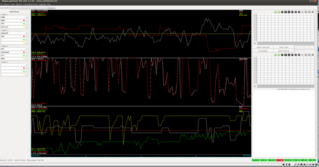
With the LC1 attached via canbus, I was hoping to end up with nice smooth AFRs. But no, they're ugly and bounce around like crazy :( middle graph is AFR and gpioadc0 (canbus input for the LC1).
I've confirmed the wideband data is getting to the MS2 through the tinyio by adjusting the ve tables up and down and can force the gauge lean/rich (though still noisy). The analog line is not even connected anymore.
My VE and timing tables are all the same values in all the cells around idle and the car was warmed up.
It seems like it's not the tinyio board having trouble either as it holds rock steady at 14.7 (error value) when the LC1 is warming up.
Things that might be bad that I can think of:
- Dead time is set to 1.00 when it looks like it should be set to 0.895 (60psi at 14v from the ID website). But would this really cause erratic AFR? i'll fix this tomorrow anyways.
- The LC1 and sensor are kinda old (5ish years, though very low use).
- No fuel pressure damper in the fuel system. Also easy to fix but seems unlikelyish.
Thoughts? Tune and log attached (pointers are appreciated, but realize this hasn't even left my garage as i'm trying to get all the sensors happy first).
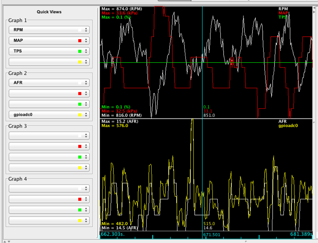
I can't quite read the numbers on the graph, but it sounds like you're getting values that are inside a plausible range. That suggests to me that the digital side of things is working just fine (or else it would be flatlined as it fails to read malformed CAN bus packets or whatever). Did you mess with the analog side? Perhaps it's not grounded properly?
I don't remember, was the sensor still hooked up while the LC-1 was along for the ride for the last x number of years?
The controller was in the car, but not powered up. Sensor was in a box. That reminds me, I don't think I did the free air when I put it in the car though, easy enough to do.
Originally Posted by codrus
I can't quite read the numbers on the graph, but it sounds like you're getting values that are inside a plausible range. That suggests to me that the digital side of things is working just fine (or else it would be flatlined as it fails to read malformed CAN bus packets or whatever). Did you mess with the analog side? Perhaps it's not grounded properly?
Yep the numbers are plausible. The CAN part seems to be working. I updated the firmware of the LC1 (yay it didn't brick) and set the analog stuff to factory defaults before doing this.
I really hope it's not silly grounding issues. Part of hooking it up via CAN was to avoid that. I could hook the analog line back up and see if it's doing the same. In fact I think I can log both? Tell the MS that the analog connection is a second WB?
I really hope it's not silly grounding issues. Part of hooking it up via CAN was to avoid that. I could hook the analog line back up and see if it's doing the same. In fact I think I can log both? Tell the MS that the analog connection is a second WB?
I dunno about secondary WB, but if nothing else you could log it as a generic sensor and post-process the datalog to convert it.
How are you powering the heater in the LC-1? The major reason I switched to CAN was that my LC-2 had a combined signal and power ground, which meant that the square wave in the heater circuit would introduce noise into the analog signal every time it switched. AIUI the LC-1 has separate grounds for the two, do you have them wired separately, or are they tied together?
How are you powering the heater in the LC-1? The major reason I switched to CAN was that my LC-2 had a combined signal and power ground, which meant that the square wave in the heater circuit would introduce noise into the analog signal every time it switched. AIUI the LC-1 has separate grounds for the two, do you have them wired separately, or are they tied together?
Originally Posted by EO2K
And is it the 7 wire super ancient LC-1 or the 5 wire moderately ancient LC-1?
It's the 5 wire only sorta ancient LC1, which has two ground wires. Both wires are grounded together at the front of the head (to the bolt that is the ground path on the front of the manifold technically).
But it doesn't matter because I got it working!
The plot doesn't look much different from the earlier one but it is! The gauge fluctuates a little(a few 1/10s of an afr point), but it's believable now.
The only thing I did was a heater calibration and then a free air calibration.
I also brought the deadtime for the injectors down to what it should be, but I did that after checking with just the wideband calibrations. This required adjustment of the VE table for the smaller dead time. It needed more fuel which seems counter intuitive given that I lowered the dead time but it's not like I really know what I'm doing
I spent the rest of the evening putting the dash panel back on to cover the hideous wiring and VHB'd the tinyio in a little box to the top of the MS. I also got in some of my fittings/lines for the turbo so I poked at that a bit. I think 36" is too long for the oil feed, might need a 24" line, but I won't know for sure until I get the manifold.
Last edited by gesso; Feb 11, 2016 at 01:45 AM.
Reason: uploaded log for posterity
Drove the car in to work today. It did great, only once stumbling a tiny bit trying to catch idle. Auto tuned the whole way in, but I took city streets and kept load/rpm low out of fear of my completely garbage ve table. Figure I'll get the low range of the table worked out and then extrapolate for the upper ranges before autotuning.
It also seems that autotune ignored my custom filter... is it ok to use || as or in the custom filter?
I need to figure out how to mount my tuning laptop as that was a bit of a pain as well.


 0
0


 just did some searching and found the same info here: https://www.miataturbo.net/megasquir...eq-fuel-68559/
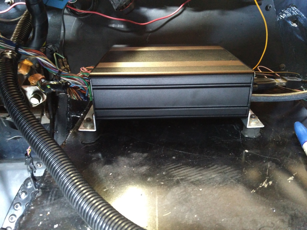
 )
)