K24Z3 Miata NB2 by ex-BMW snob - "Booger" Story of a Benchwarmer to Starting Line-up
 01-25-2022, 07:55 AM
#41
Junior Member
Thread Starter

Join Date: Sep 2021
Location: Louisville, KY
Posts: 231
Total Cats: 50
Yes,
Thanks for the tips! I did trim everything per the KPower instructions. I guess I'll find out about the exhaust as the motor is already set in place (posts are a day delayed). Will have to check the dowel "noise" after start up. The exhaust was pre-bolted to the motor to check for clearance to the 6 speed transmission as it was indeed a tight fit. Glad it was test fit as more material was removed to make it fit.
 QXTW1383 by D S, on Flickr
 SKXD2934 by D S, on Flickr
 IMG_1248 by D S, on Flickr
 IMG_1247 by D S, on Flickr
Thanks for the tips! I did trim everything per the KPower instructions. I guess I'll find out about the exhaust as the motor is already set in place (posts are a day delayed). Will have to check the dowel "noise" after start up. The exhaust was pre-bolted to the motor to check for clearance to the 6 speed transmission as it was indeed a tight fit. Glad it was test fit as more material was removed to make it fit.
QXTW1383 by D S, on FlickrSKXD2934 by D S, on FlickrIMG_1248 by D S, on FlickrIMG_1247 by D S, on FlickrLast edited by bimmerboy; 01-25-2022 at 08:08 AM.

Reply
 1
1

1
01-25-2022, 08:02 AM
#42
Junior Member
Thread Starter
Join Date: Sep 2021
Location: Louisville, KY
Posts: 231
Total Cats: 50
The issue right now is that the KPower RWD wiring harness has (4) connectors that are wrong. Here's one example... See the ears and horns are in different spots. It's the Honda water temp sensor. This is a similar case for the Acuity TPS and others.
KPower says that a few of these harnesses were shipped to customers (wish they gave me a heads up as I've had this harness for weeks). So the options are 1) to check their stock for a "good" harness and ship out, 2) send this harness back for correction, or 3) send me connectors and I will attempt to re-pin. I will know more today.
 HNLH7041 by D S, on Flickr
KPower says that a few of these harnesses were shipped to customers (wish they gave me a heads up as I've had this harness for weeks). So the options are 1) to check their stock for a "good" harness and ship out, 2) send this harness back for correction, or 3) send me connectors and I will attempt to re-pin. I will know more today.
HNLH7041 by D S, on Flickr
Reply
3
3
01-27-2022, 07:15 AM
#43
Junior Member
Thread Starter
Join Date: Sep 2021
Location: Louisville, KY
Posts: 231
Total Cats: 50
Exactly 48hrs after alerting KPower of my wiring harness woes, had a new "correct" harness in my hands. Thanks @KMiata!!! Installed harness, intake, throttle cable, radiator hoses, serpentine belt, and a few other odds and ends. Installed the KPower exhaust, which was an an absolute dream!.. everything bolted in and lined up perfect without any issues. Tightest clearance is at driver seat bucket and between the diff and rear subframe. But no bangs during a wiggle test even with the original rubber hanger mounts. If I do notice banging on track the first step would be to replace those with new.
 Fuel line questions - Luckily this is an NB2 so only a single fuel line is needed. The fuel line you see in photo is only temporary. What is the permanent fix? Hard tube to -AN adapter under the car, 5ft or so of 6-AN hose, and a -AN to quick release adapter to the injector rail? How reliable are these hard tube to -AN adapters? How many feet of -AN line did you use?
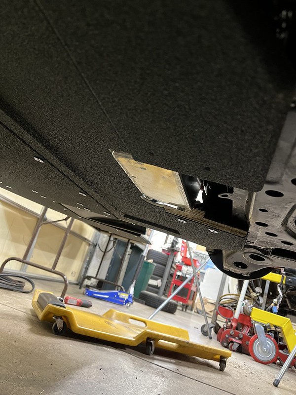
I haven't seen a K swap Miata NB2 with all the braces. So here are my findings: 1) The strut tower brace obviously wouldn't fit. 2) The lower subframe cross brace didn't fit with the down pie cross member basically occupying it's spot. 3) The front x-brace needed to be notched and filled to clear the down pipe. It is possible that 5-spd users would not have this problem as the interference was only very slight and if I fitted the down pipe against the transmission it would clear. But with the notch and a little adjustment, there is around 3/16" between trans and brace.
 IMG_1267 by D S, on Flickr
 IMG_9125 by D S, on Flickr
Fuel line questions - Luckily this is an NB2 so only a single fuel line is needed. The fuel line you see in photo is only temporary. What is the permanent fix? Hard tube to -AN adapter under the car, 5ft or so of 6-AN hose, and a -AN to quick release adapter to the injector rail? How reliable are these hard tube to -AN adapters? How many feet of -AN line did you use?I haven't seen a K swap Miata NB2 with all the braces. So here are my findings: 1) The strut tower brace obviously wouldn't fit. 2) The lower subframe cross brace didn't fit with the down pie cross member basically occupying it's spot. 3) The front x-brace needed to be notched and filled to clear the down pipe. It is possible that 5-spd users would not have this problem as the interference was only very slight and if I fitted the down pipe against the transmission it would clear. But with the notch and a little adjustment, there is around 3/16" between trans and brace.
IMG_1267 by D S, on FlickrIMG_9125 by D S, on Flickr
Reply
2
2
 01-27-2022, 03:55 PM
#45

Yes, I appreciate all the updates, it reminds me how far behind I am on my own K24Z3 project.
Quick question - is that your wideband plugged into the exhaust tube right by the head? I thought those were there for EGT sensors and that an oxygen sensor that close to the exhaust ports would burn up almost immediately.
Quick question - is that your wideband plugged into the exhaust tube right by the head? I thought those were there for EGT sensors and that an oxygen sensor that close to the exhaust ports would burn up almost immediately.
Reply
0
0
01-27-2022, 04:48 PM
#46
Junior Member
Thread Starter
Join Date: Sep 2021
Location: Louisville, KY
Posts: 231
Total Cats: 50
I don't actually know. I ordered the O2 sensor listed in the KPower installation instructions and installed it where every photo I've ever seen has it installed. The 2nd port is for a 2nd O2 sensor (wideband?). I believe the sensor I have is wideband capable but it is not wired up to the KPro ECU to work in that capacity.
Reply
0
0
01-30-2022, 06:53 AM
#47
Junior Member
Thread Starter
Join Date: Sep 2021
Location: Louisville, KY
Posts: 231
Total Cats: 50
Intake and IAT installed. The Honda part number used for the IAT was 37880-PLC-004. Any instructions regarding an IAT was not mentioned anywhere in the KPower instructions that I found (but I may be wrong). I had not even purchased the sensor until the wiring harness had a connector labeled IAT which I promptly googled. Going to add another splash shield/ wheel liner as well in addition to the guard that came with the cone filter. Got the parts from siliconeintakes.com for anyone interested.
Also added an oil separator between the PVC port and intake. Per KPower I left the PCV valve intact and plan to just add a breather filter on the valve cover port.
 IMG_1277 by D S, on Flickr
 IMG_1278 by D S, on Flickr
 IMG_1281 by D S, on Flickr
Also added an oil separator between the PVC port and intake. Per KPower I left the PCV valve intact and plan to just add a breather filter on the valve cover port.
IMG_1277 by D S, on FlickrIMG_1278 by D S, on FlickrIMG_1281 by D S, on Flickr
Reply
0
0
01-30-2022, 06:51 PM
#48
Junior Member

Join Date: Jan 2016
Location: Atlanta, GA
Posts: 457
Total Cats: 332
Haha, we built our intakes from the same place.
Once I got my hands on that filter I realized its probilby wayyyy to small. I planned to replace mine with a larger K&N once I figure out how much space I have to work with.
Once I got my hands on that filter I realized its probilby wayyyy to small. I planned to replace mine with a larger K&N once I figure out how much space I have to work with.
Reply
0
0
 02-01-2022, 06:42 PM
#50
Junior Member
Thread Starter
Join Date: Sep 2021
Location: Louisville, KY
Posts: 231
Total Cats: 50
After spending 6 or more hours triple checking all wiring splices, connections and the 4 grounds we installed and not finding an issue. We had spark but appeared weak, had fuel pressure, had power to the injectors.
We kept thinking the injectors weren't firing, no clicking and thought they were stuck. We "pinged" each one with 12 volts and they all clicked and we smelled gas through the exhuast. The tip off was checking voltage at the injectors with a multi meter. Checking voltage and using the where the harness ground was bolted to cam cover we saw 10.3v but checking to the timing cover ground was 12.5. We unbolted the timing cover ground on the chassis (we have 2 other engine to chassis grounds plus bellhouse to chassis and the PPF to chassis) and bolt it to the cam cover we have 12.5v and the the engine fired right up. So if you feel like you have no fuel, check the voltage at the injectors. Each injector has a common 12V supply when the ignition key is on. Make sure there is actually 12V.
I had followed the assembly manual to a tee and believe it is good, I would suggest adding an additional ground strap from the head to the cam cover then to the chassis.
It was a day of head scratching an frustration but worked through it, I can’t think of a project like this that I have done that I haven’t one of those days.
Bottom line is it starts right up like a stock TSX, runs smooth and sounds great.
This is actually the first "start"... the first time it fired and died as the idle set screw wasn't set and wasn't caught on video.
 ground by D S, on Flickr
We kept thinking the injectors weren't firing, no clicking and thought they were stuck. We "pinged" each one with 12 volts and they all clicked and we smelled gas through the exhuast. The tip off was checking voltage at the injectors with a multi meter. Checking voltage and using the where the harness ground was bolted to cam cover we saw 10.3v but checking to the timing cover ground was 12.5. We unbolted the timing cover ground on the chassis (we have 2 other engine to chassis grounds plus bellhouse to chassis and the PPF to chassis) and bolt it to the cam cover we have 12.5v and the the engine fired right up. So if you feel like you have no fuel, check the voltage at the injectors. Each injector has a common 12V supply when the ignition key is on. Make sure there is actually 12V.
I had followed the assembly manual to a tee and believe it is good, I would suggest adding an additional ground strap from the head to the cam cover then to the chassis.
It was a day of head scratching an frustration but worked through it, I can’t think of a project like this that I have done that I haven’t one of those days.
Bottom line is it starts right up like a stock TSX, runs smooth and sounds great.
This is actually the first "start"... the first time it fired and died as the idle set screw wasn't set and wasn't caught on video.
ground by D S, on Flickr
Reply
1
1
02-01-2022, 09:37 PM
#51
Cpt. Slow

iTrader: (25)
Join Date: Oct 2005
Location: Oregon City, OR
Posts: 14,204
Total Cats: 1,138
You can't ground on the valve cover, it's not connected to the block, the valve cover gasket and bolt grommets isolate it. You can bolt under one of the valve cover acorn nuts, since it goes directly to the cam caps, then block. So that main harness ground you have on the valve cover isn't actually grounded, until you added that valve cover to timing cover ground.
Reply
0
0
02-02-2022, 09:51 AM
#52
Junior Member
Join Date: Jan 2016
Location: Atlanta, GA
Posts: 457
Total Cats: 332
You can't ground on the valve cover, it's not connected to the block, the valve cover gasket and bolt grommets isolate it. You can bolt under one of the valve cover acorn nuts, since it goes directly to the cam caps, then block. So that main harness ground you have on the valve cover isn't actually grounded, until you added that valve cover to timing cover ground.
I got away with grounding everything on the engine to a 10mm bolt back by the cam sensors(by everything I mean the extra coil pack ground), then an engine to chassis ground at the stock Miata place on the engine shelf. I didn't bother grounding the valve cover or timing cover. I suppose if the K24A2 sensor your using needs grounding though the timing cover for whatever reason, you can run a ground directly from timing cover to engine block, but I don't see the point of grounding the valve cover itself. Just more wiring.
Congratulations on getting it fired up though! That was a huge moral boost for me when I got mine running, I'm sure you feel the same.
Last edited by Wingman703; 02-02-2022 at 10:05 AM.
Reply
0
0
02-02-2022, 07:22 PM
#53
Junior Member
Thread Starter
Join Date: Sep 2021
Location: Louisville, KY
Posts: 231
Total Cats: 50
Question:
What water temps should I expect on track with this setup? Or at least what temp should I have KPro trigger the fan? Hondata forums says don't rely on the ECU... a thermo switch should be used. But for a track only car, the only time you would need the fan is in the paddock and during a red flag. Why wouldn't I rely on the ECU?
What water temps should I expect on track with this setup? Or at least what temp should I have KPro trigger the fan? Hondata forums says don't rely on the ECU... a thermo switch should be used. But for a track only car, the only time you would need the fan is in the paddock and during a red flag. Why wouldn't I rely on the ECU?
Reply
0
0
02-03-2022, 02:13 AM
#54

If you're drafting someone during a race you could start to have your temps climb, and having a fan kick on as a last ditch effort for getting rising temps under control isn't a terrible idea. That's weird that Hondata can't control a damn fan.
Looking at track videos of K24Z3 cars that have data overlays it seems like they maybe get to 200F in nice weather. I'm going to have my PDM set to turn fan on at 185, turn back off at 180, but only if the car is going less than 20MPH, or if it gets over 212 for any reason.
Looking at track videos of K24Z3 cars that have data overlays it seems like they maybe get to 200F in nice weather. I'm going to have my PDM set to turn fan on at 185, turn back off at 180, but only if the car is going less than 20MPH, or if it gets over 212 for any reason.
Reply
0
0
02-03-2022, 06:56 AM
#55
Junior Member
Thread Starter
Join Date: Sep 2021
Location: Louisville, KY
Posts: 231
Total Cats: 50
The ECU can control the fan and it does. So it sounds like 212 would be my on temp for the fan. Hondata doesn't recommend relying solely on the ECU to trigger the fan. They say to use a thermal switch first and if that thermal switch ever fails then the ECT will trigger the fan above the set point.
Reply
0
0
02-03-2022, 09:27 AM
#57
Could you also wire in a fan override switch? That way you could control whether you want it on or off depending on what you're seeing. I had one in my first track car years and years ago and basically just turned it on for in the paddock or extreme circumstances on track where I anticipated the temperature to keep climbing, but really didn't use it that much. I don't know what the K24 runs as its normal operating temperature, but I would probably set the fan to come on around stock Miata values (210 or so) and see what the temp stabilizes at first time you take it out and romp on it. If it stabilizes in the 190-200 range then I would think 210 for ECU control would be good and having an override switch means you could kick it on whenever you needed even before reaching that temp (moving around the paddock, red flag before letting it creep up on it's own, etc).
Reply
0
0
02-03-2022, 01:33 PM
#58
Junior Member
Thread Starter
Join Date: Sep 2021
Location: Louisville, KY
Posts: 231
Total Cats: 50
Yes, a manual switch would be very easy. Just add it in parallel to the same wire that the ECU used to complete ground for the fan relay. That way, the ECU would turn on at say 215 and anything below that is driver based.
Reply
0
0
02-03-2022, 01:39 PM
#59
Could you also wire in a fan override switch? ... I would think 210 for ECU control would be good and having an override switch means you could kick it on whenever you needed even before reaching that temp (moving around the paddock, red flag before letting it creep up on it's own, etc).
Reply
0
0
02-04-2022, 07:08 PM
#60
Junior Member
Thread Starter
Join Date: Sep 2021
Location: Louisville, KY
Posts: 231
Total Cats: 50
Ignore the stock seat... it's just temporary and more of a courtesy for the dyno tuner. My bucket seat is rather small.
LRB door cards installed as this car is retaining the power windows. FYI... there are not much lighter (if at all) then the factory door cards but man do they look race car!
Also cut out the 9LR splitter to make room for the KPower oil pan and drain plugs @flier129 .
Just a few details before its time to head to the dyno.
 IMG_1304 by D S, on Flickr
 IMG_1297 by D S, on Flickr
 IMG_1298 by D S, on Flickr
 IMG_1302 by D S, on Flickr
LRB door cards installed as this car is retaining the power windows. FYI... there are not much lighter (if at all) then the factory door cards but man do they look race car!
Also cut out the 9LR splitter to make room for the KPower oil pan and drain plugs @flier129 .
Just a few details before its time to head to the dyno.
IMG_1304 by D S, on FlickrIMG_1297 by D S, on FlickrIMG_1298 by D S, on FlickrIMG_1302 by D S, on Flickr
Last edited by bimmerboy; 02-07-2022 at 07:00 AM.
Reply
1
1


