NOT A MIATA, FE3N+HOLSET+73 FORD COURIER BUILD
 08-17-2016, 09:28 PM
#21
Senior Member
Thread Starter

Join Date: Jan 2011
Location: sacramento ,ca
Posts: 563
Total Cats: 160
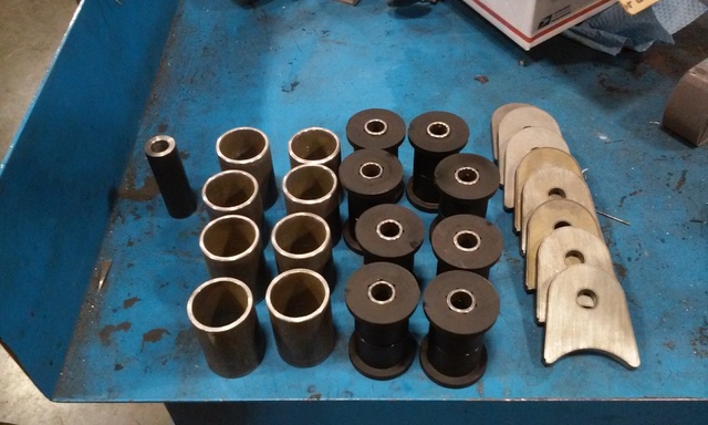
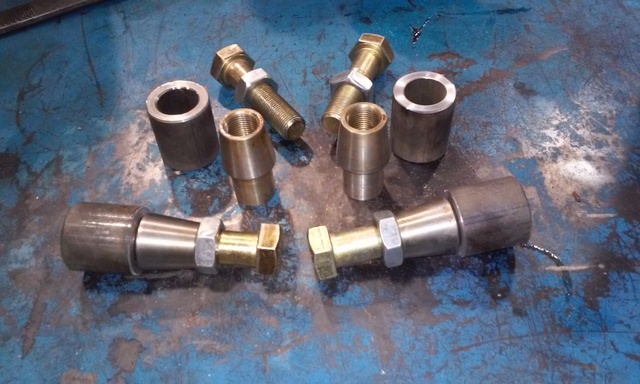
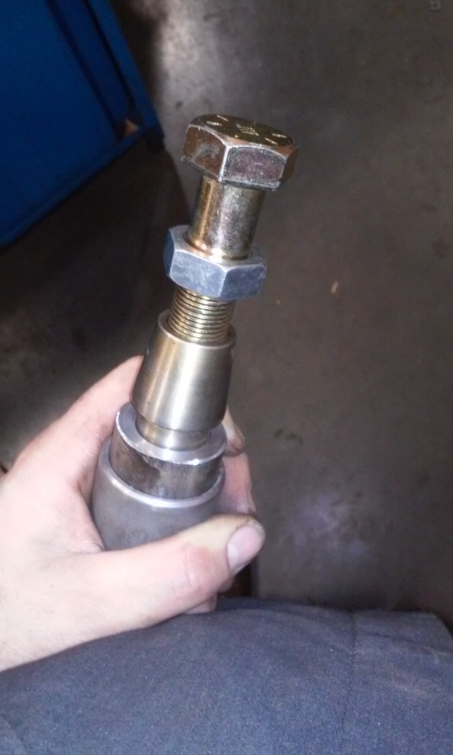
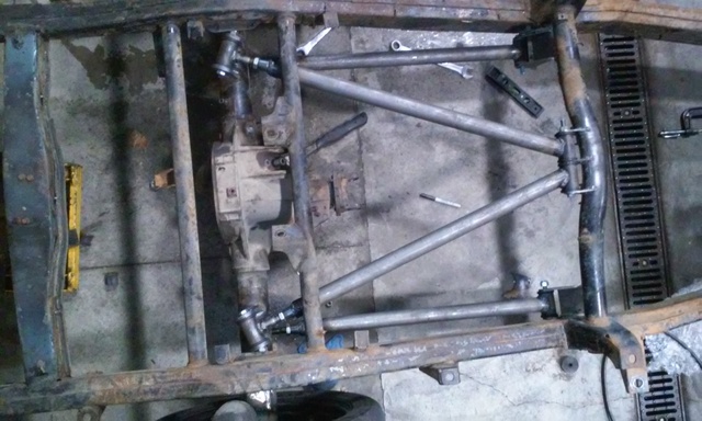
picking up the pieces to install my 4 link this weekend. the threaded bungs i got were 1" OD so i made some sleeves out of 1.5" .250" wall DOM to fit them snugly into the 1.75" .125" wall DOM im using for the links.
cut all the stock tabs off of the 8.8 so its ready for the 4 link tabs. i grossly underestimated how much time and grinding that this would take.
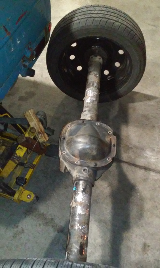
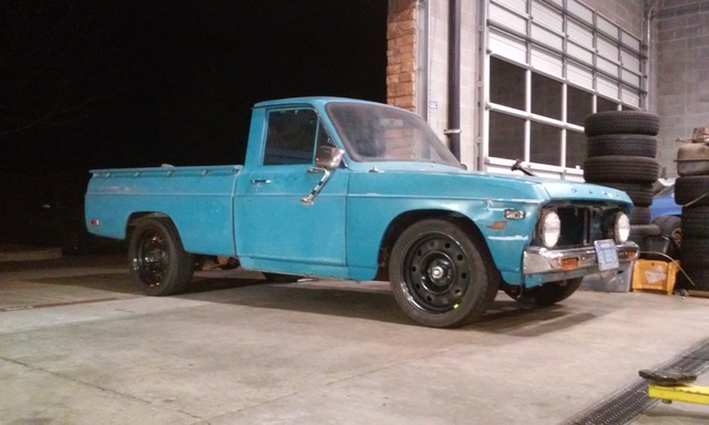
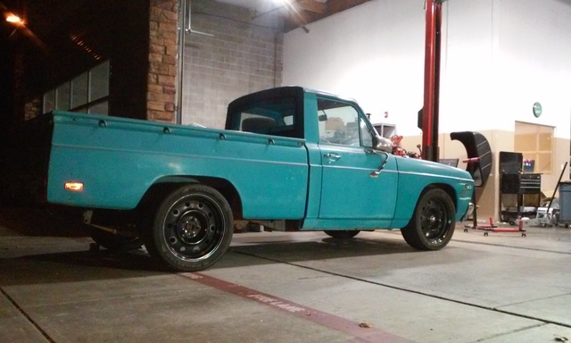
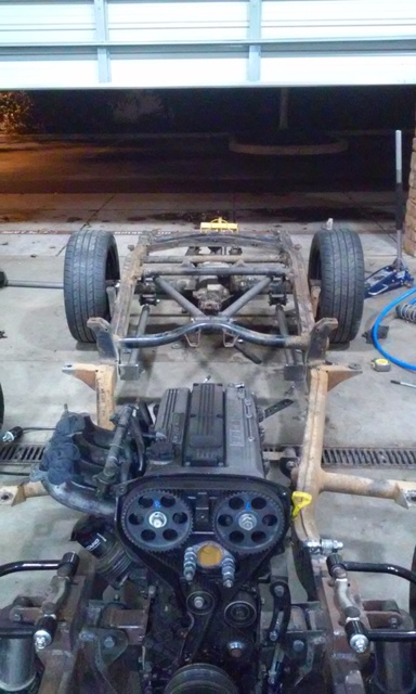
i fabbed up some sleeves to replace the front coil springs and made spacers for the rear to set ride height to give me an idea of what needed to be where. its a little higher than i thought it would be but it still looks good. if i decide to slam it out i can get drop spindles to keep my control arm alignment in the front.
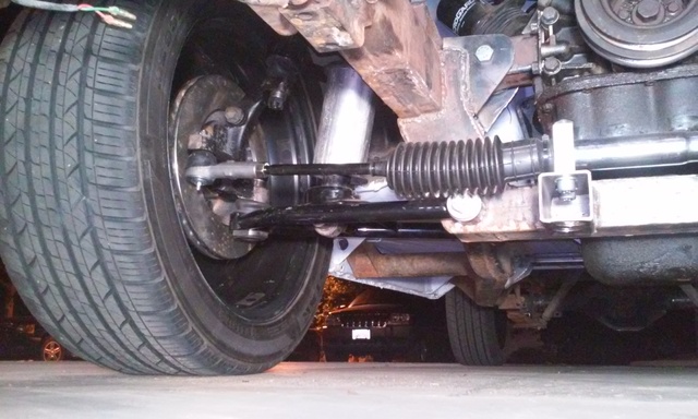
cut all the stock tabs off of the 8.8 so its ready for the 4 link tabs. i grossly underestimated how much time and grinding that this would take.
i fabbed up some sleeves to replace the front coil springs and made spacers for the rear to set ride height to give me an idea of what needed to be where. its a little higher than i thought it would be but it still looks good. if i decide to slam it out i can get drop spindles to keep my control arm alignment in the front.

Reply
 0
0

0
08-17-2016, 09:29 PM
#22
Senior Member
Thread Starter
Join Date: Jan 2011
Location: sacramento ,ca
Posts: 563
Total Cats: 160
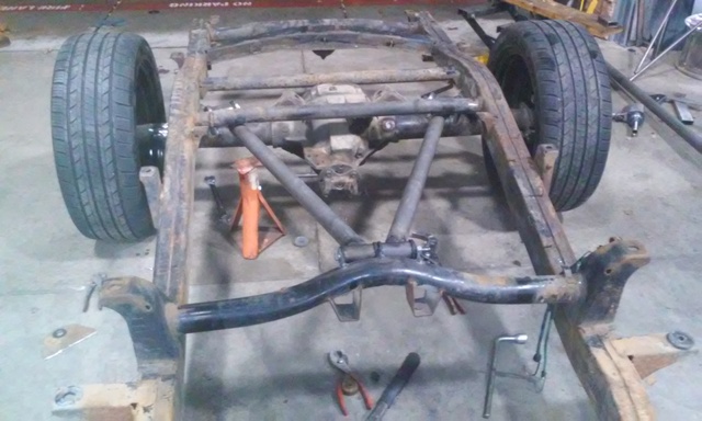
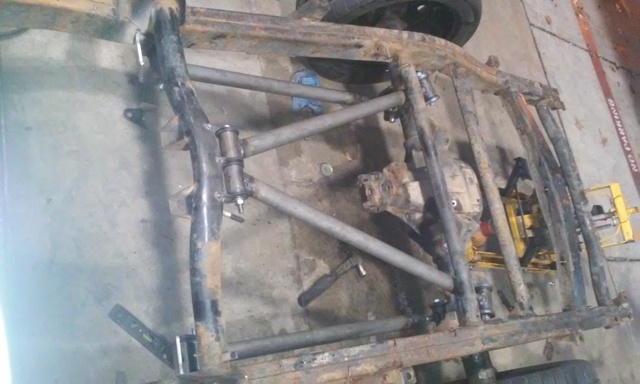
doin more work. seemed like i didnt really get **** done this weekend cause it takes forever to plan out **** than to actually build it. only have 2 links done but i know where the other 2 are going so the fab work should go quickly.
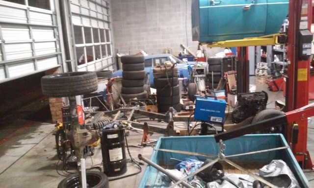
pulled the cab and bed off so i could take accurate measurements and make sure everything is perfectly lined up. measured everything at least 20 times before welding. then measures 10 more after tacking it in place.
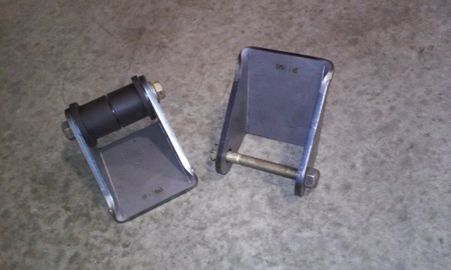
trying to get the most angle and still keeping it true 4 link i combined the top frame mount 3 tabs, 2 bushings one bolt.
the links
pulled the cab and bed off so i could take accurate measurements and make sure everything is perfectly lined up. measured everything at least 20 times before welding. then measures 10 more after tacking it in place.
trying to get the most angle and still keeping it true 4 link i combined the top frame mount 3 tabs, 2 bushings one bolt.
the links
Reply
0
0
08-17-2016, 09:31 PM
#23
Senior Member
Thread Starter
Join Date: Jan 2011
Location: sacramento ,ca
Posts: 563
Total Cats: 160
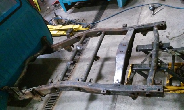
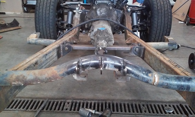
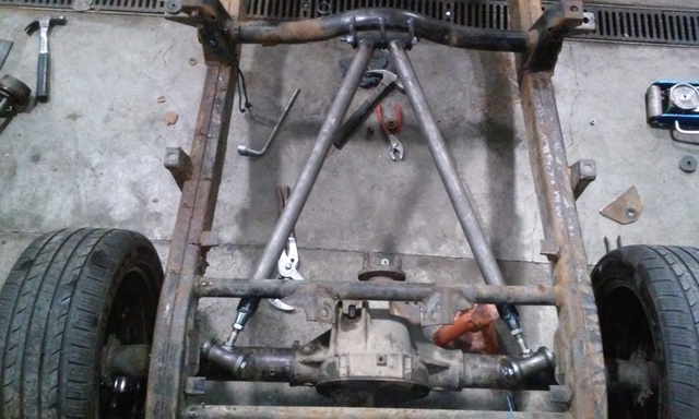
finished the lower bars and got the brackets tacked into place. ill pull the rear end out tonight and finish welding it all in and mock up the coil over tabs. ill also cut the crossmember out thats over the pinion while im at it.
i think im going to have the frame powder coated and obnoxious neon orange like this. i think it will pop with the blue

i think im going to have the frame powder coated and obnoxious neon orange like this. i think it will pop with the blue
Reply
0
0
08-17-2016, 09:32 PM
#24
Senior Member
Thread Starter
Join Date: Jan 2011
Location: sacramento ,ca
Posts: 563
Total Cats: 160
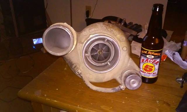
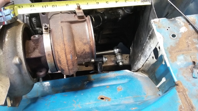
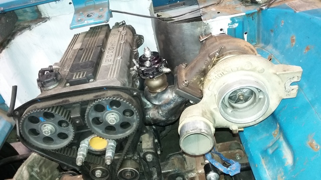
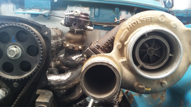
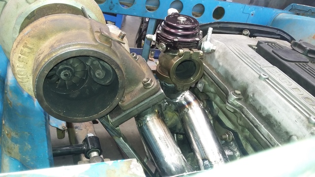
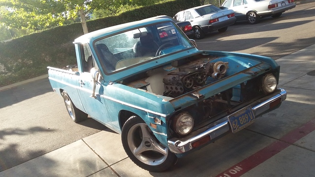
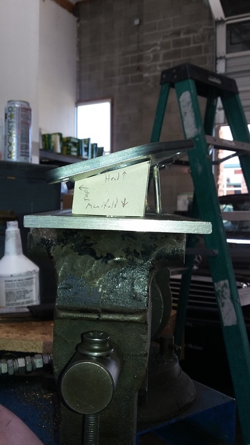
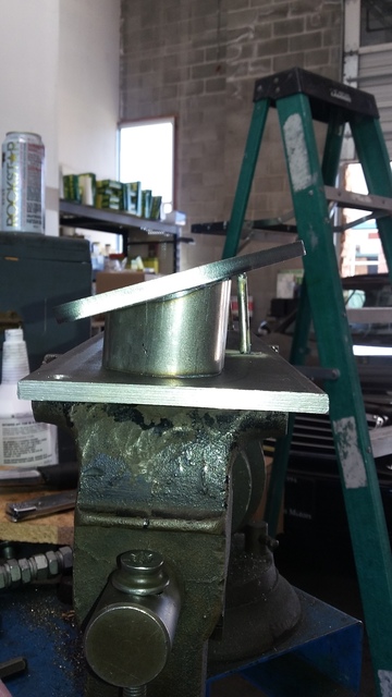
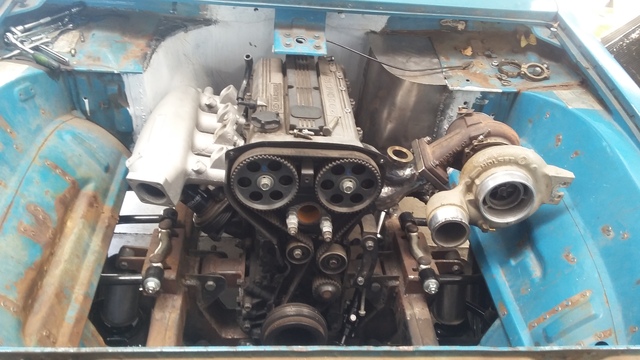
i finally found someone selling a Holset that is not a ******* flake. i want fast spool and drivabiility over peak power so i was looking at HY35's but came across this HE341W for $200. spins freely and has zero play. im so happy to finally have it to start mocking up my engine bay!
Reply
0
0
08-17-2016, 09:33 PM
#25
Senior Member
Thread Starter
Join Date: Jan 2011
Location: sacramento ,ca
Posts: 563
Total Cats: 160
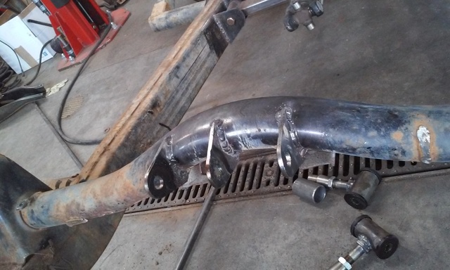
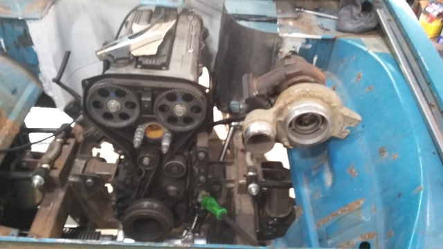
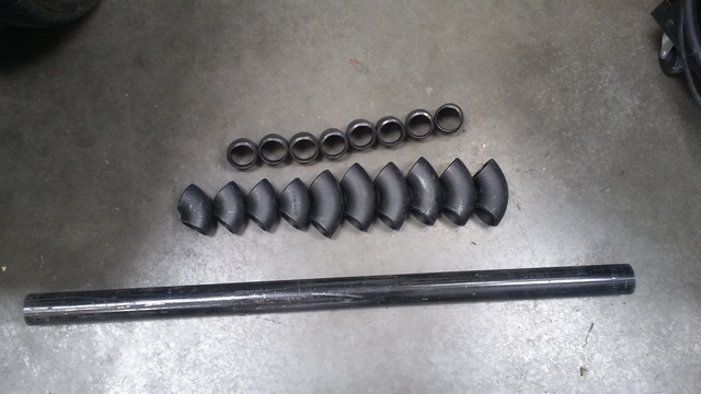
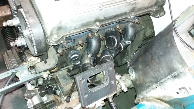
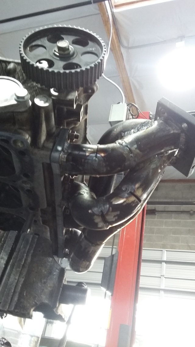
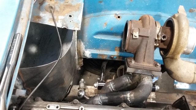
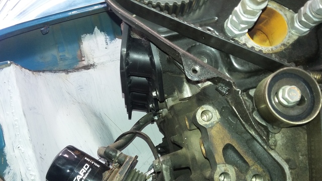
its slow going to to lack of funds and its hella nice out so ive been on my mountain bike a lot. a buddy of mine had my flanges laser cut so i can start mocking up the manifold. heres where the turbo is gonna go.
Reply
0
0
 08-17-2016, 09:37 PM
#29
Senior Member
Thread Starter
Join Date: Jan 2011
Location: sacramento ,ca
Posts: 563
Total Cats: 160
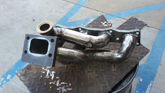
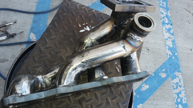
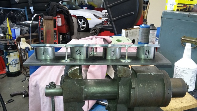
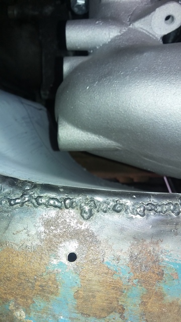
i ran out of argon before i could finish all of the bottom welds but its just about done. trying to figure out the order to do the finish welding in was a pain and took forever.
had to weld up 1,2,& 4 with 3 out then weld the 1-3 collector elbow onto the T3 flange. then the elbow off of thttp://www.----------------------/forum/Themes/core/images/bbc/ftp.gifhe head flange had to be welded completely to the straight bit. it left just enough room between 1&2 runners to fit the torch in there to finish off #3
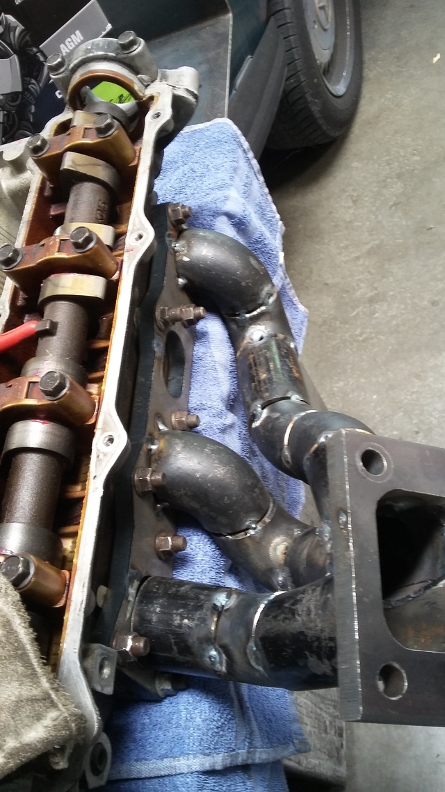
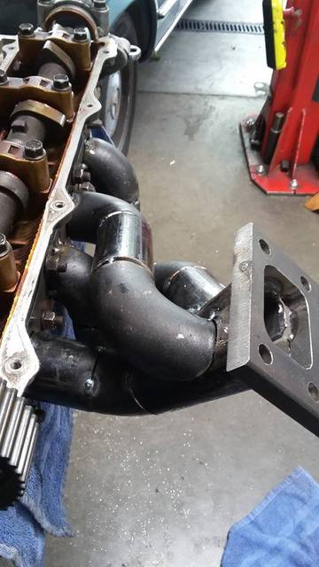
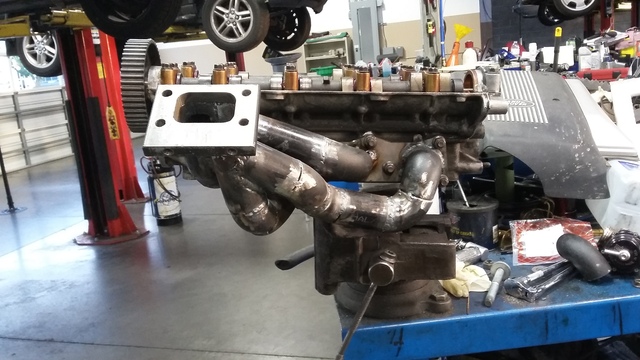
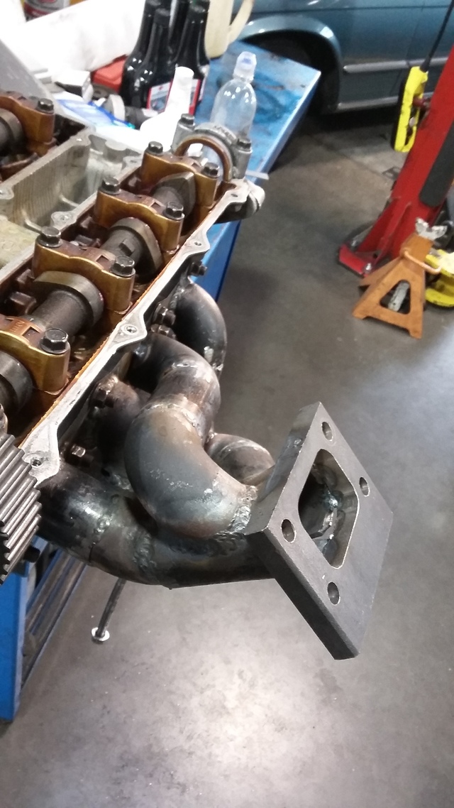
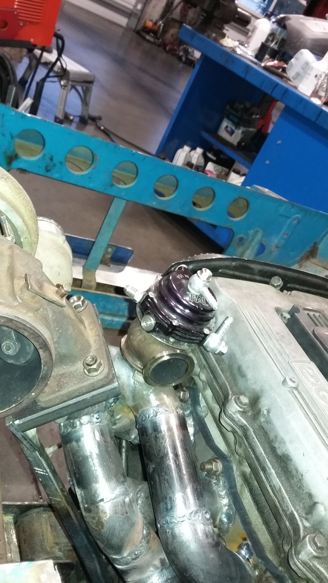
looks like the only spot to mount my Tial MVS is gonna be straight on top of my #3 runner. ive seen manifolds that do this but not sure how i feel about only tapping into 1 runner for the wastegate. even if its right at the collector.
had to weld up 1,2,& 4 with 3 out then weld the 1-3 collector elbow onto the T3 flange. then the elbow off of thttp://www.----------------------/forum/Themes/core/images/bbc/ftp.gifhe head flange had to be welded completely to the straight bit. it left just enough room between 1&2 runners to fit the torch in there to finish off #3
looks like the only spot to mount my Tial MVS is gonna be straight on top of my #3 runner. ive seen manifolds that do this but not sure how i feel about only tapping into 1 runner for the wastegate. even if its right at the collector.
Reply
0
0
 08-17-2016, 09:40 PM
#31
Senior Member
Thread Starter
Join Date: Jan 2011
Location: sacramento ,ca
Posts: 563
Total Cats: 160
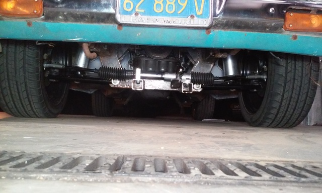
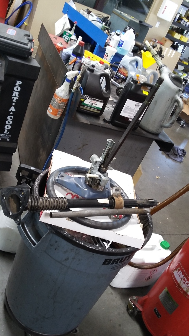
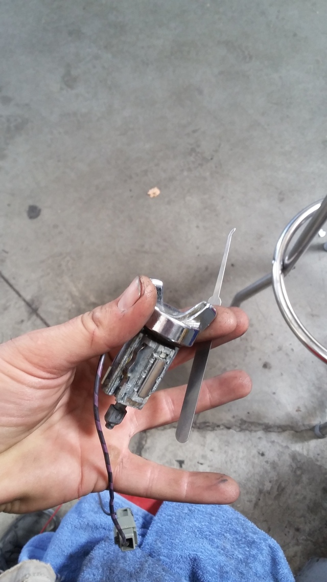
started out with a bronco 2 tilt column cause it was the most compact. cut abut a foot off of the housing and cut the outer support cup off and welded it to the shorter shaft. i was able to pic the ignition lock and bought a new replacement from autozone for $16 with 2 keys
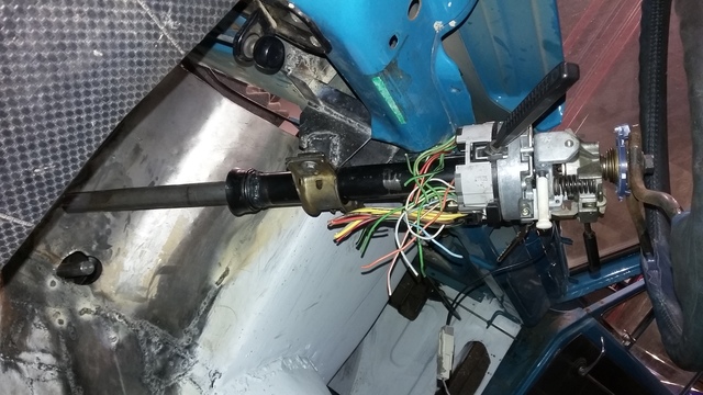
i tacked the piece of angle to the firewall and built this shitty bracket to hold it all up. after every thing was tacked in place i broke the tacks to remove and fully weld all the seams.
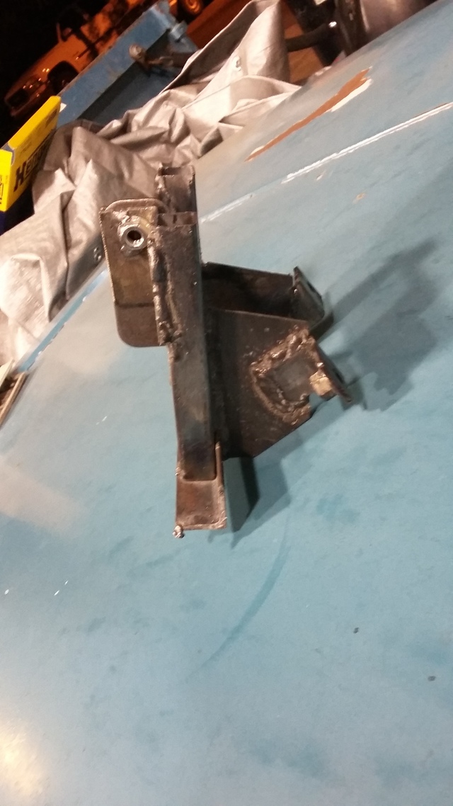
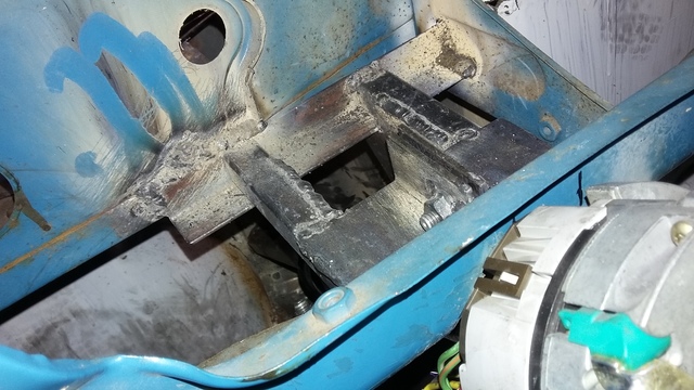
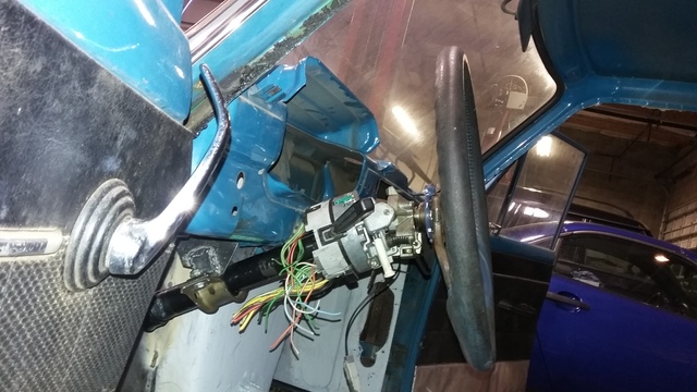
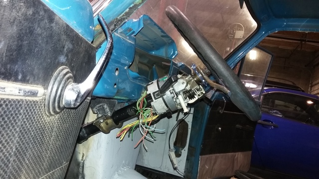
i tacked the piece of angle to the firewall and built this shitty bracket to hold it all up. after every thing was tacked in place i broke the tacks to remove and fully weld all the seams.
Reply
0
0
08-17-2016, 09:41 PM
#32
Senior Member
Thread Starter
Join Date: Jan 2011
Location: sacramento ,ca
Posts: 563
Total Cats: 160
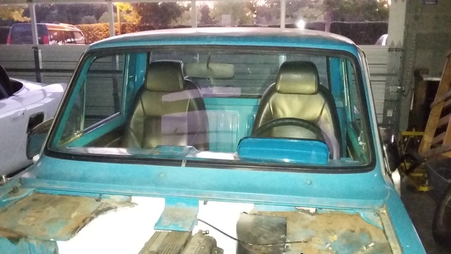
Slow progress is still progress... finally got my passenger seat rails welded in and the seat mounted. Sold one of my cars so I finally have some cash to order parts and hopefully get this thing running.
Reply
0
0
 08-17-2016, 09:42 PM
#34
Senior Member
Thread Starter
Join Date: Jan 2011
Location: sacramento ,ca
Posts: 563
Total Cats: 160
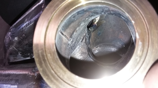
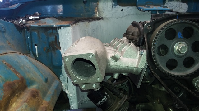
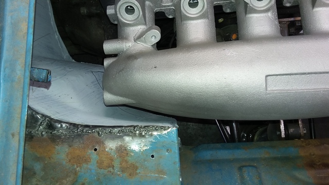
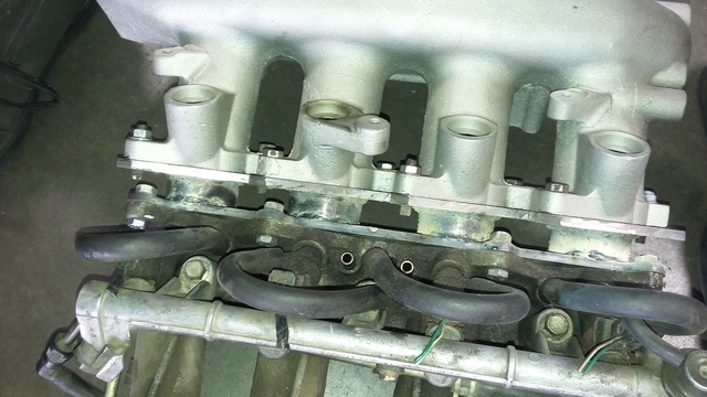
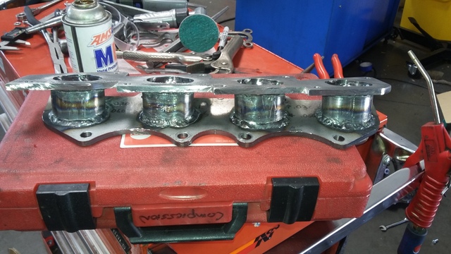
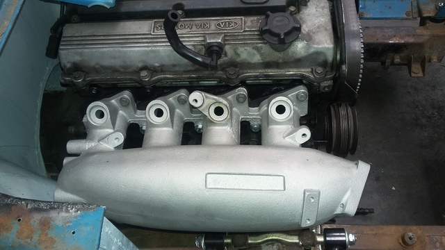
bought a Greddy knock off s13 sr20det intake manifold. the casting looks like garbage and they machined a one of the vacuum ports wrong and put a hole in it. My expectations were pretty low for $89 shipped but i was still disappointed. if this works i may buy a real Greddy manifold. . i decided to build an adapter instead of just swapping flanges because the runners in the head are pretty steep pointing up and the runners on the manifold point down. i figured rotating the flanges for a straight shot would increase power potential.
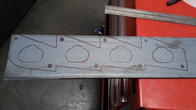
i didnt have an SR20DET flange so i had to make one. i would usually use a gasket as a stencil fot the flange but it wont be here til Friday and im impatient. i used a trick my high school auto shop teacher taught me, thin cardboard/paper put a couple of bolts in the holes and hammer. traced the template onto steel and cut it with a plasma cutter. then used a carbide cutter to smooth it out
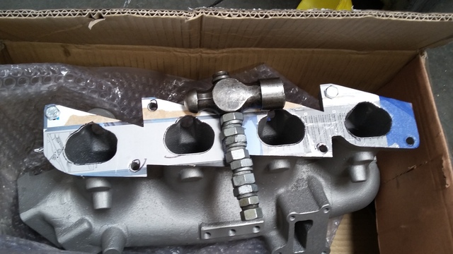
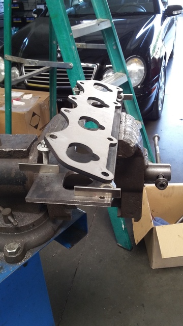
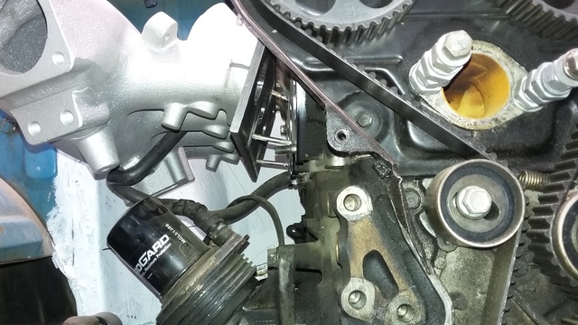
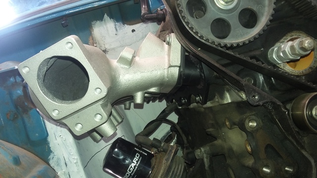
put the manifold against the head to work out what angle it needed to be then tack welded the two flanges together to make sure everything would bolt up. and it does. i can still get my oil filter off too which is nice.
im building the runners today so more pics later
i didnt have an SR20DET flange so i had to make one. i would usually use a gasket as a stencil fot the flange but it wont be here til Friday and im impatient. i used a trick my high school auto shop teacher taught me, thin cardboard/paper put a couple of bolts in the holes and hammer. traced the template onto steel and cut it with a plasma cutter. then used a carbide cutter to smooth it out
put the manifold against the head to work out what angle it needed to be then tack welded the two flanges together to make sure everything would bolt up. and it does. i can still get my oil filter off too which is nice.
im building the runners today so more pics later
Reply
0
0
08-17-2016, 09:45 PM
#35
Senior Member
Thread Starter
Join Date: Jan 2011
Location: sacramento ,ca
Posts: 563
Total Cats: 160
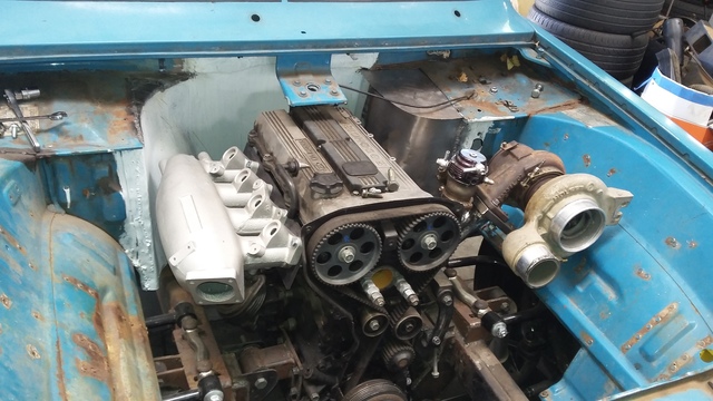
done!
a little confusing to look at but i bolted both flanges to the intake manifolds to keep them from warping while welding.
[img]htttp://i271.photobucket.com/albums/jj146/aintnobitch/courier/20160717_151913.jpg[/img]
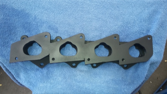
painted all pretty
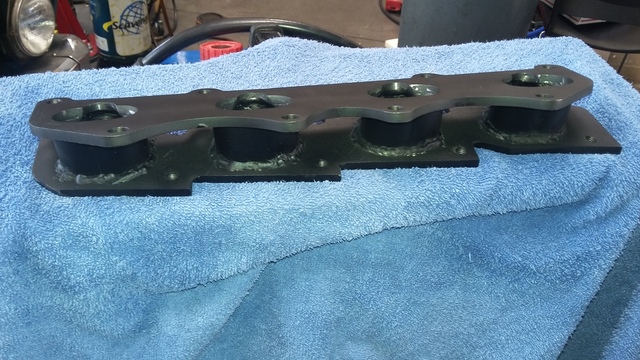
final assembly
a little confusing to look at but i bolted both flanges to the intake manifolds to keep them from warping while welding.
[img]htttp://i271.photobucket.com/albums/jj146/aintnobitch/courier/20160717_151913.jpg[/img]
painted all pretty
final assembly
Reply
0
0


