
Pat's Ebay Turbo Compound Boost Build

Thread Starter
Elite Member
iTrader: (16)
Joined: Aug 2007
Posts: 9,406
Total Cats: 559
From: Houston, TX
I'm was running all of it, I'm thinking of turning it up higher.
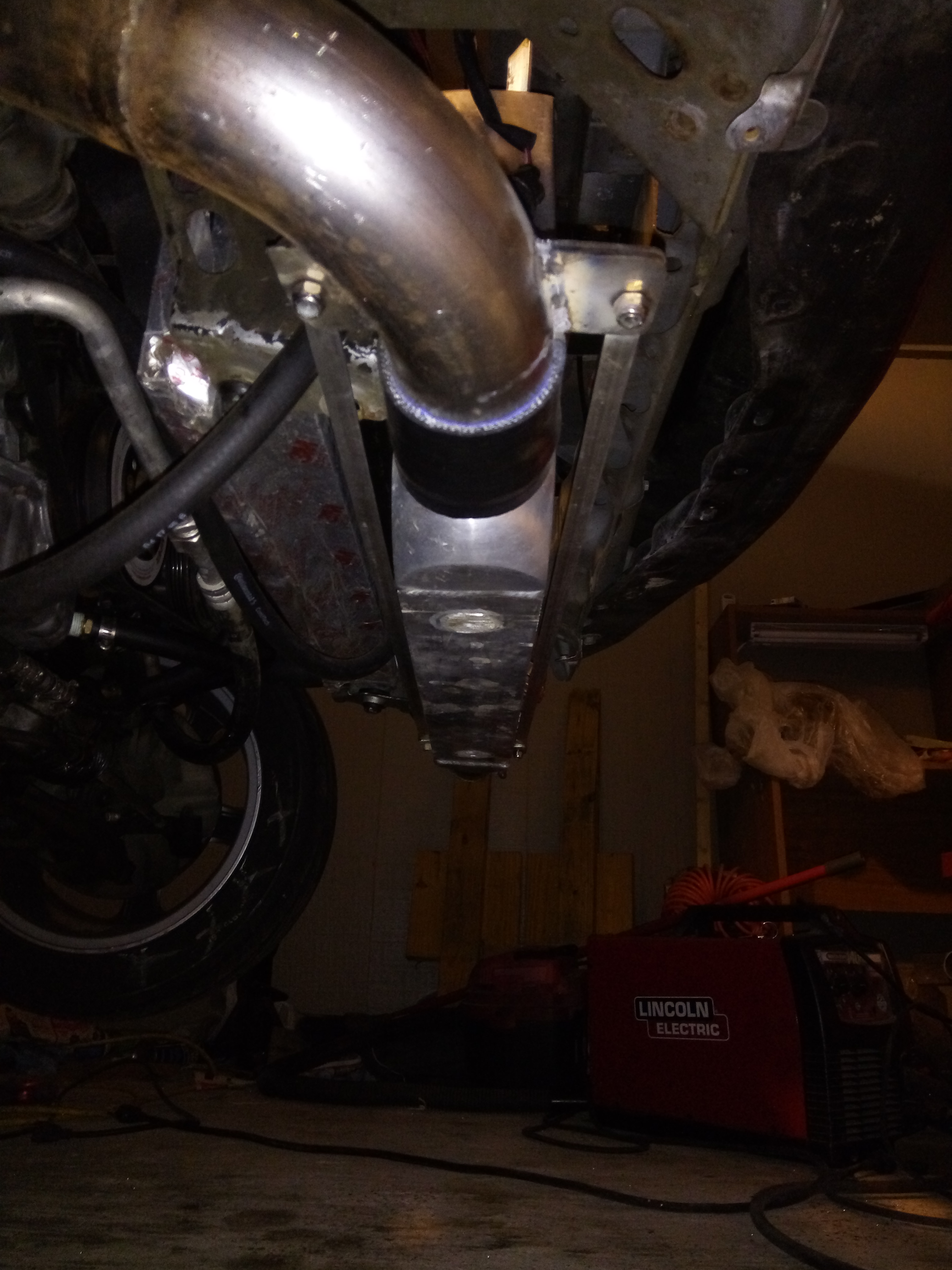
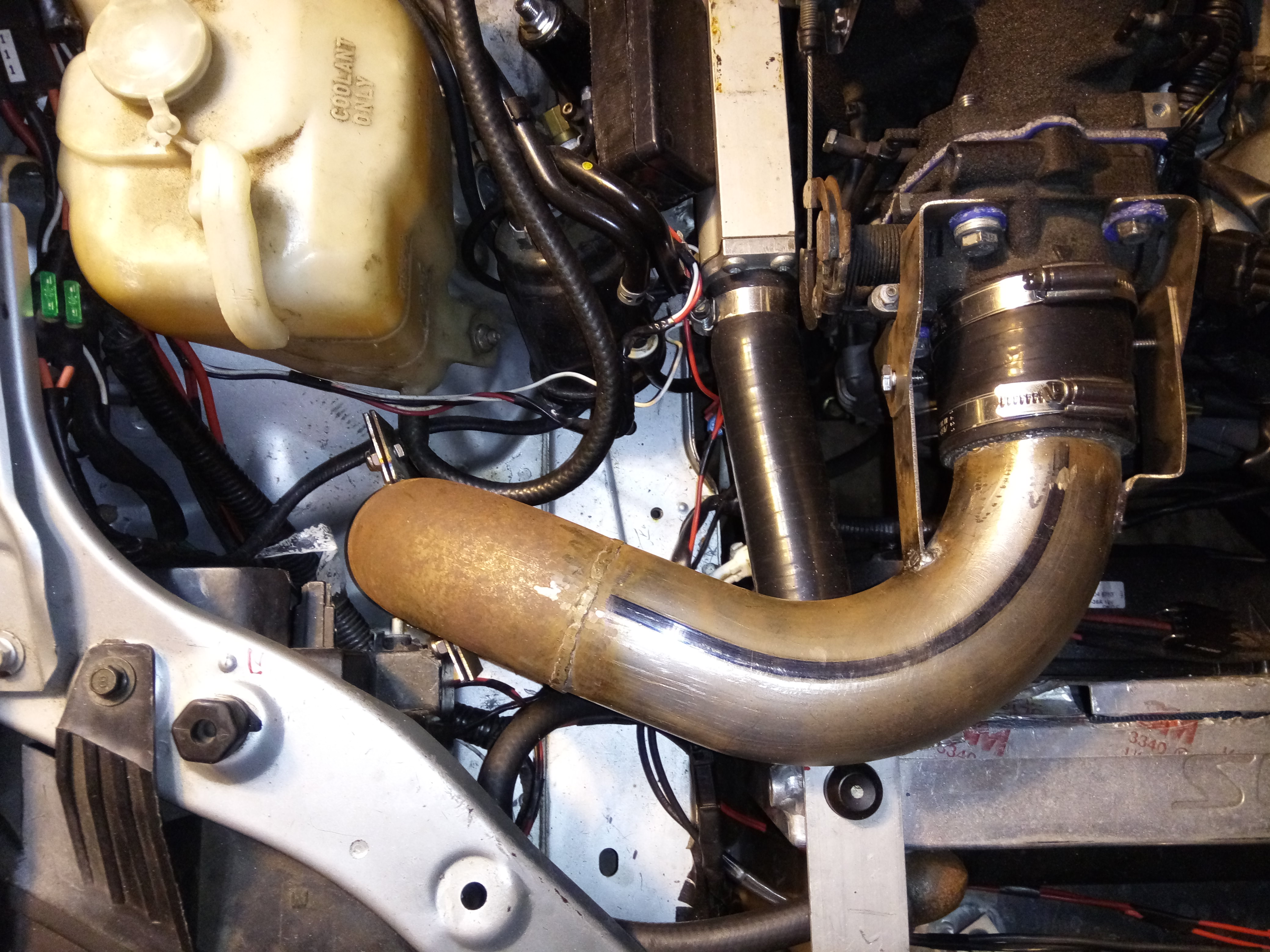
Small update, I got the intercooler pipe made for the passenger side. It was a pain to get it to clear everything but it now fits. I started on drivers side, it will be easier but I'm done for today.
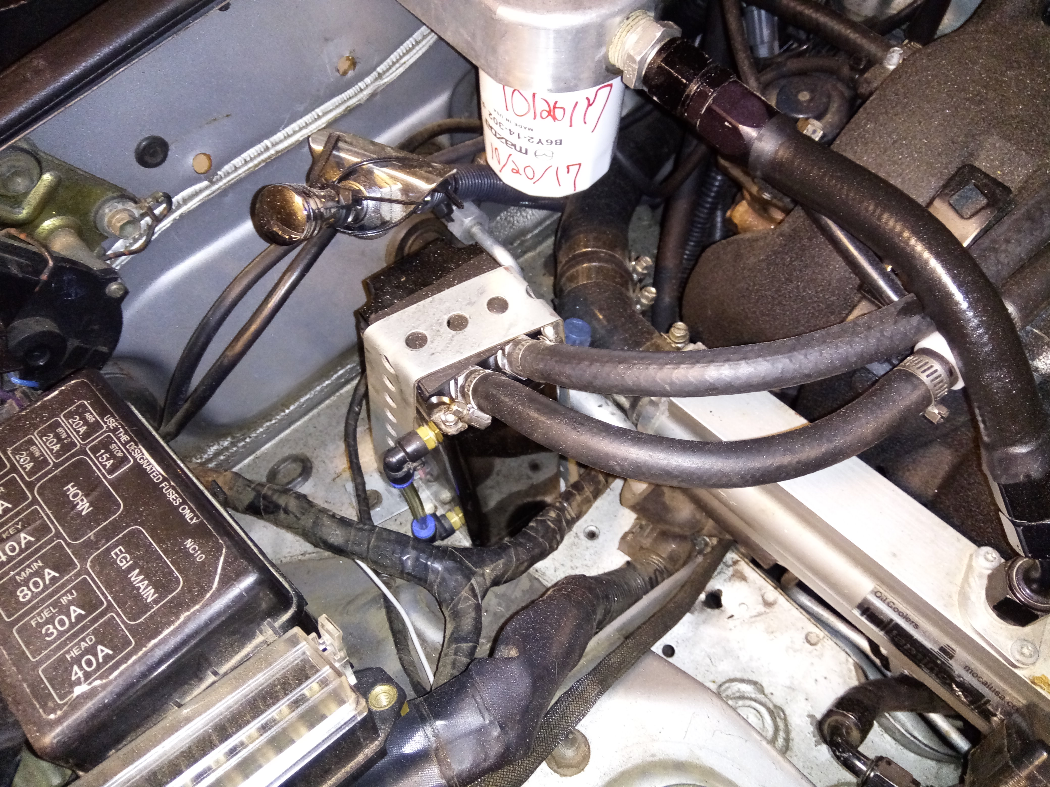
Also got a new oil feed hose for the turbo as old one wouldn't work, needed a 90* end to hook to the turbo now. Today was just one of those days where I didn't get as much done as I wanted, even though I put in a good amount of time.
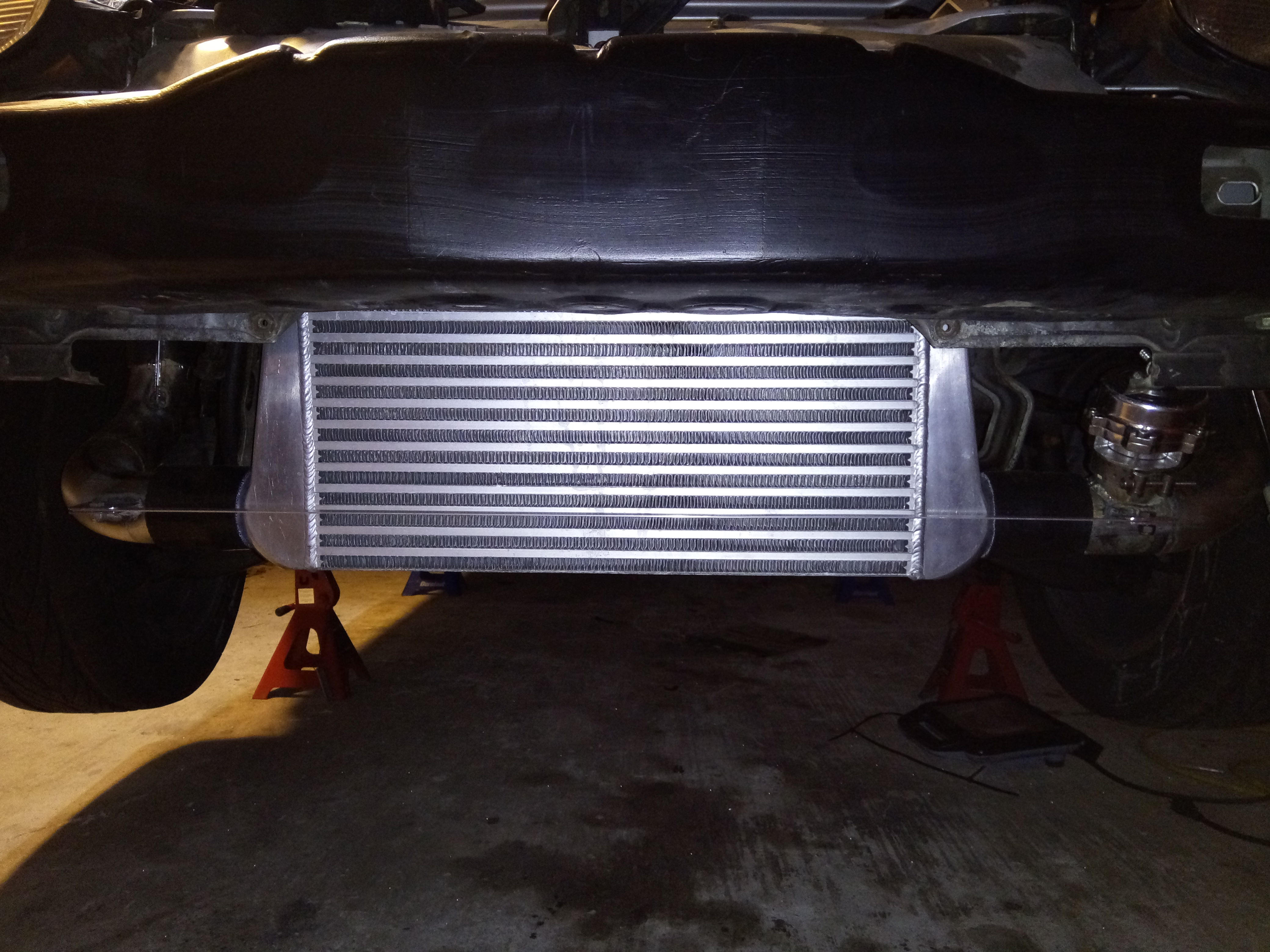
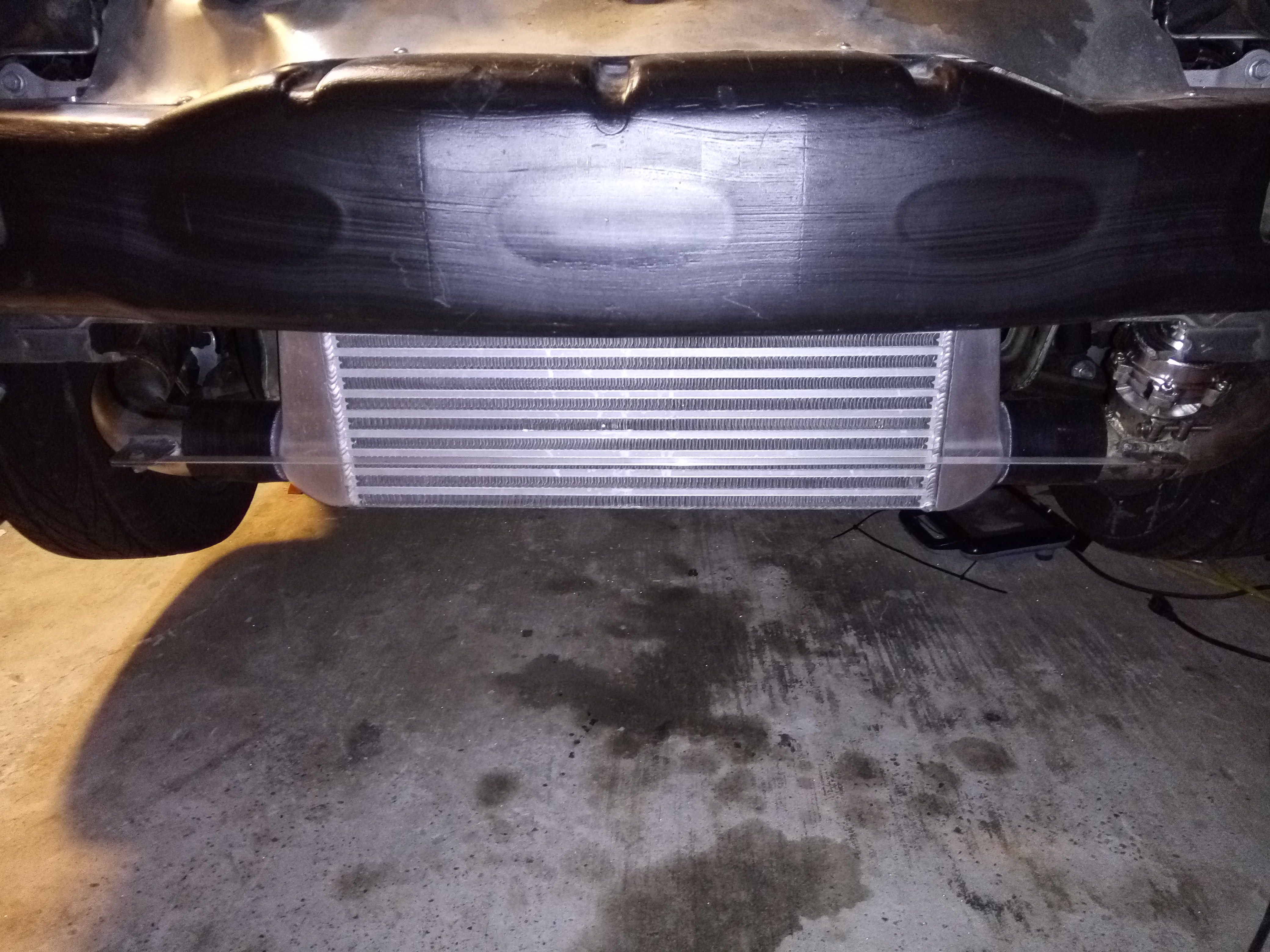
Plus side, the intercooler looks baller!
Small update, I got the intercooler pipe made for the passenger side. It was a pain to get it to clear everything but it now fits. I started on drivers side, it will be easier but I'm done for today.
Also got a new oil feed hose for the turbo as old one wouldn't work, needed a 90* end to hook to the turbo now. Today was just one of those days where I didn't get as much done as I wanted, even though I put in a good amount of time.
Plus side, the intercooler looks baller!
Reply
 0
0

0
Thread Starter
Elite Member
iTrader: (16)
Joined: Aug 2007
Posts: 9,406
Total Cats: 559
From: Houston, TX
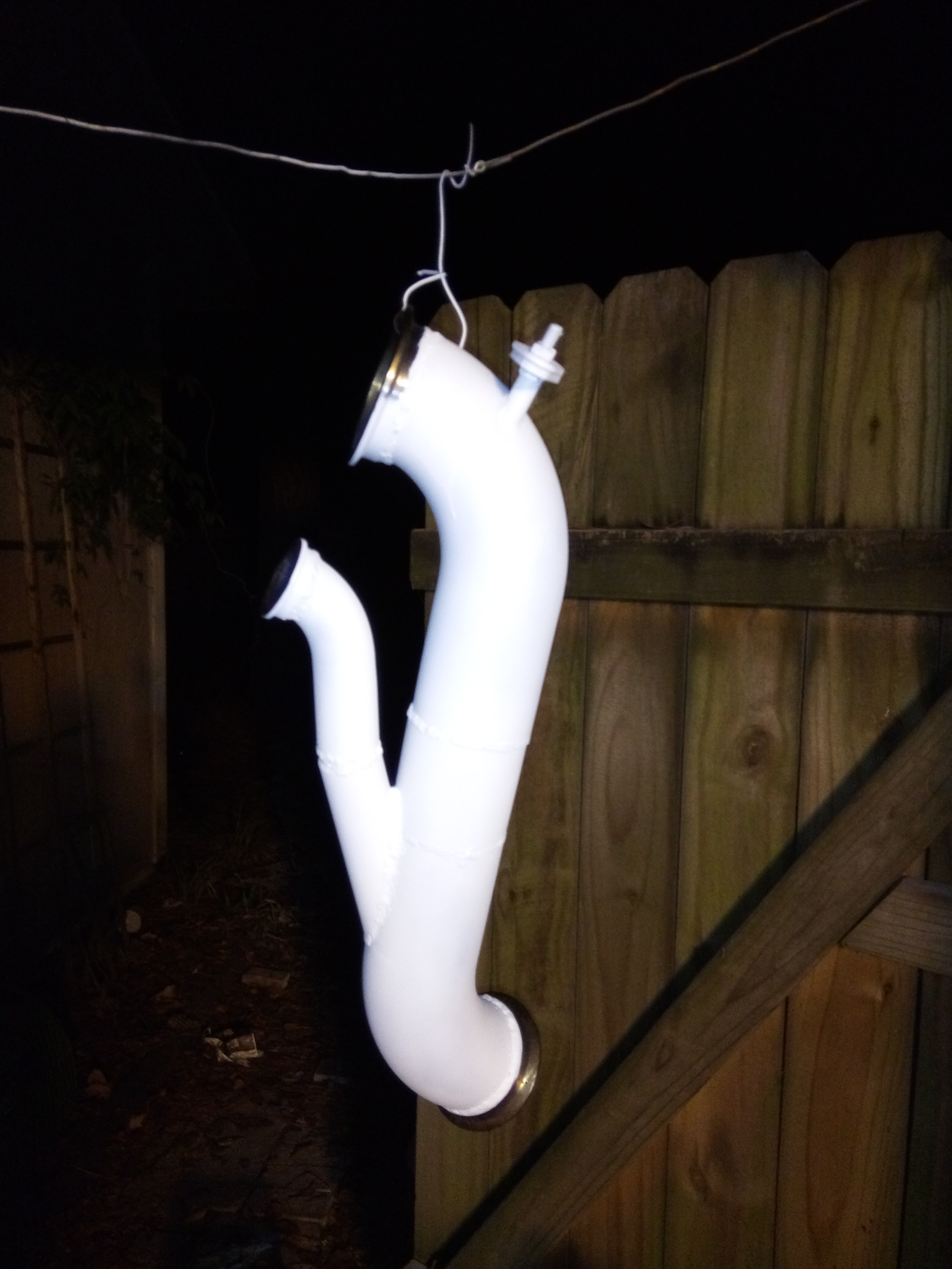
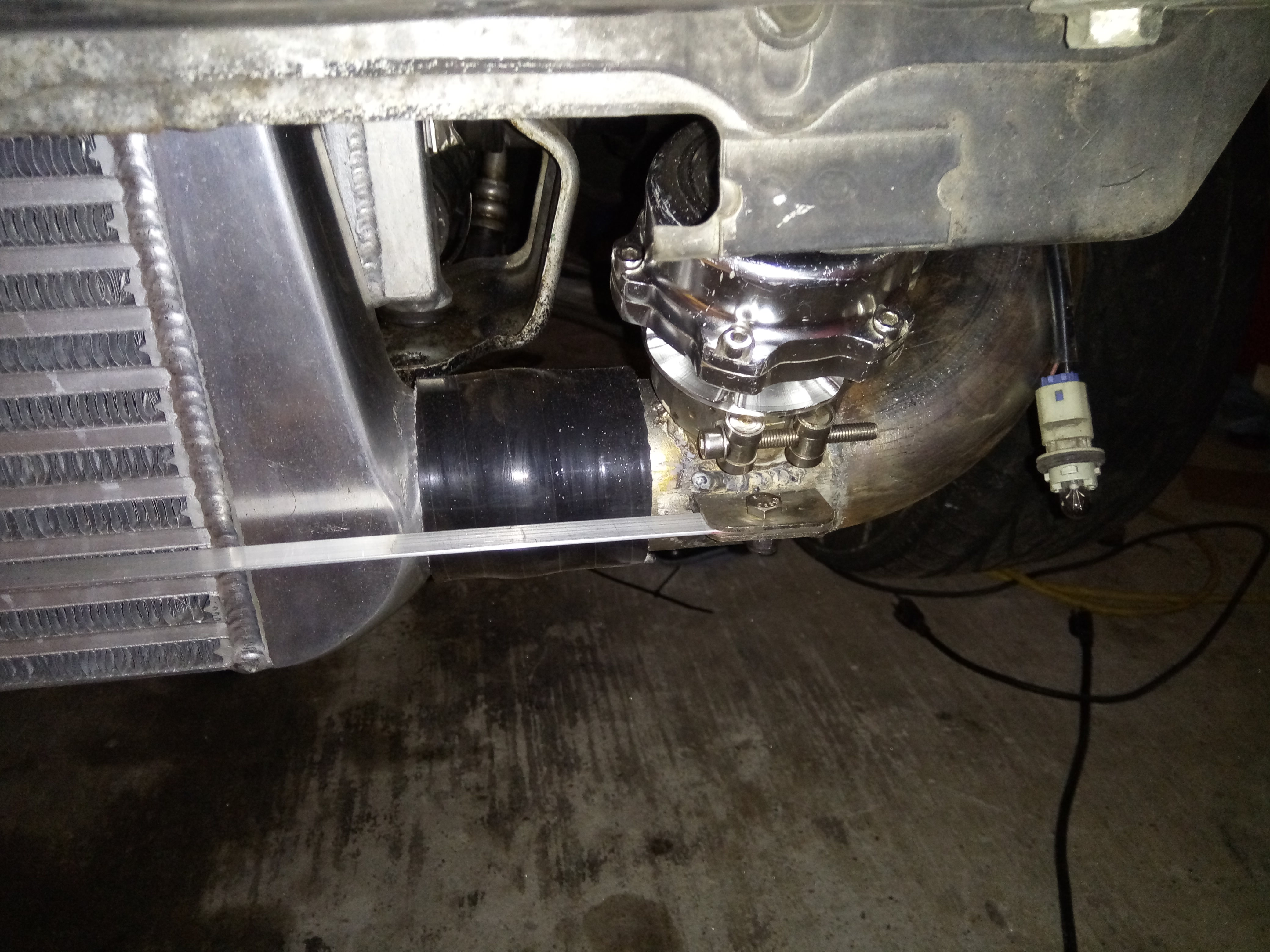
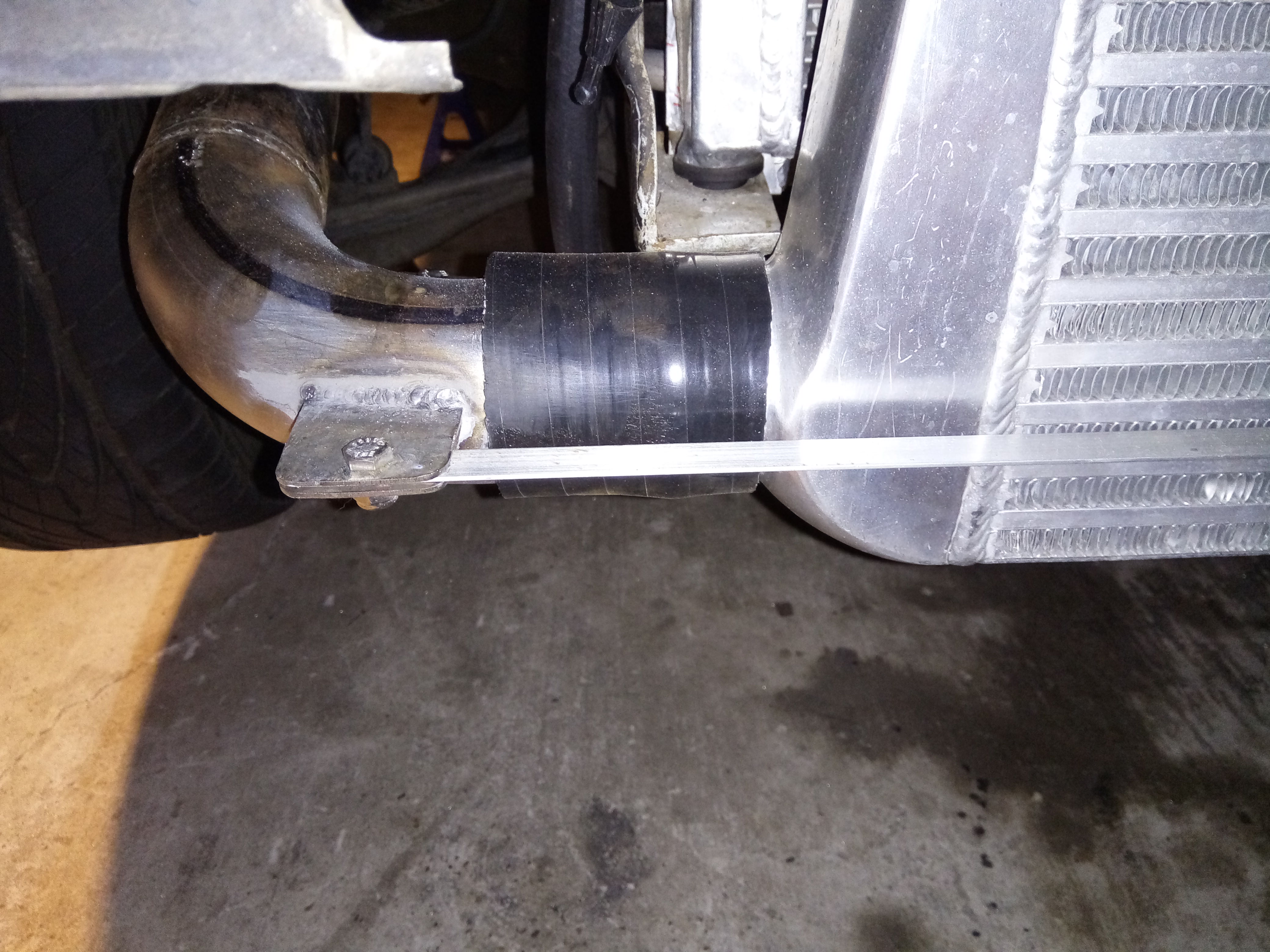
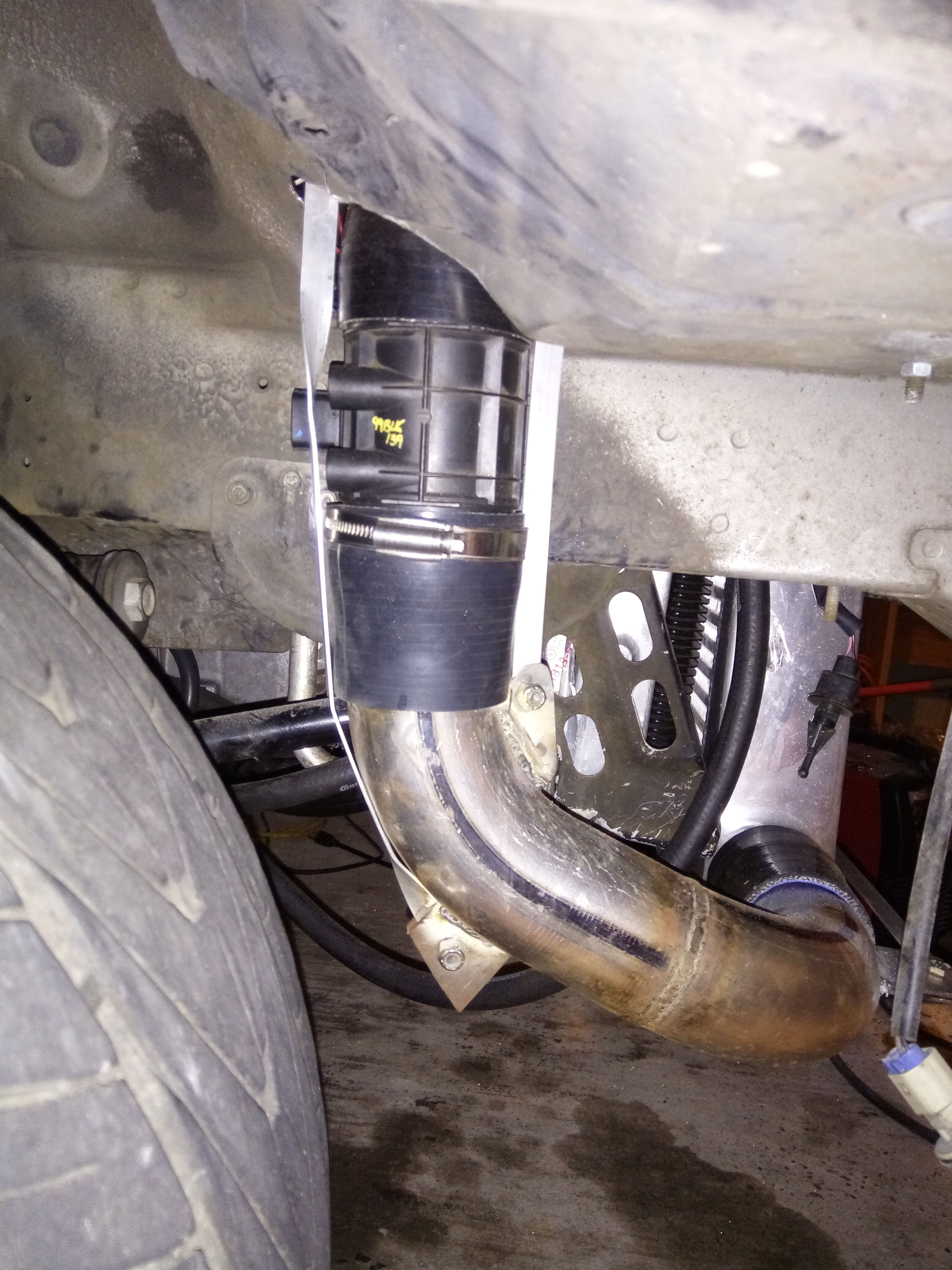
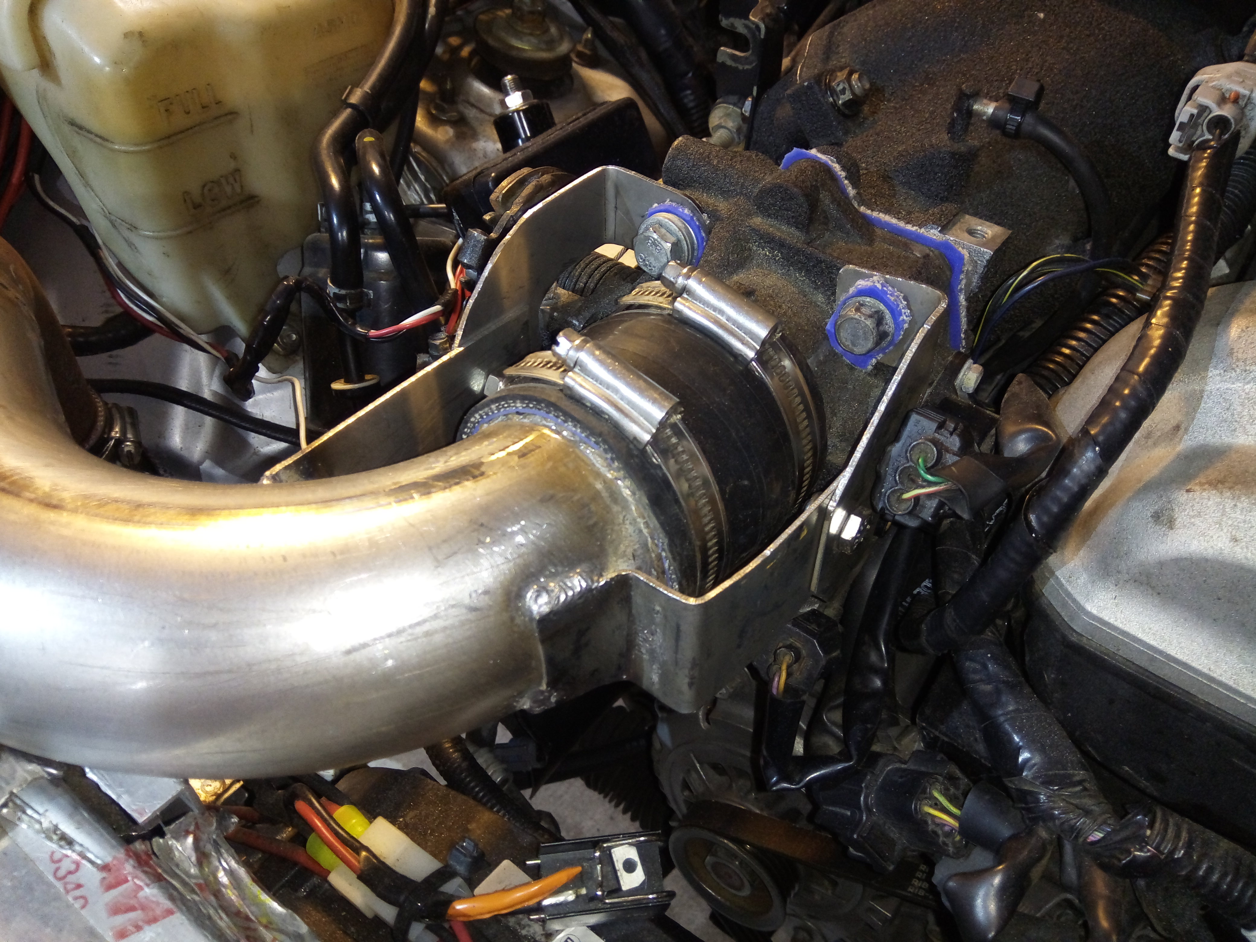
Another small update, but managed to make a little progress. Drivers side intercooler pipe is made. The turbo has a 2" to 2.5" silicone 90* transition clamped to it, and the intercooler has a 2.5" straight silicone coupler clamped to it. The pipe itself goes between these is all metal, welded, one piece, and has the BOV on it too. And has a mounting tab on it that bolts to the chassis near the turbo. Also built the mounts for the intercooler so it's supported and those are done, they bolt to the chassis and to the intercooler. Then I started working on the support system for the silicone couplers, but didn't make much progress on that. Hope to get more done tomorrow.
Reply
0
0

Joined: Aug 2014
Posts: 1,462
Total Cats: 389
From: Bainbridge Island, WA
Another small update, but managed to make a little progress. Drivers side intercooler pipe is made. The turbo has a 2" to 2.5" silicone 90* transition clamped to it, and the intercooler has a 2.5" straight silicone coupler clamped to it. The pipe itself goes between these is all metal, welded, one piece, and has the BOV on it too. And has a mounting tab on it that bolts to the chassis near the turbo. Also built the mounts for the intercooler so it's supported and those are done, they bolt to the chassis and to the intercooler. Then I started working on the support system for the silicone couplers, but didn't make much progress on that. Hope to get more done tomorrow.
__________________
Reply
0
0
Thread Starter
Elite Member
iTrader: (16)
Joined: Aug 2007
Posts: 9,406
Total Cats: 559
From: Houston, TX
I'll try to get some pics up soon. I didn't take many pics during fabrication as I haven't had a lot of time to work on the car, so I was trying to get as much done as I could with the time I have.
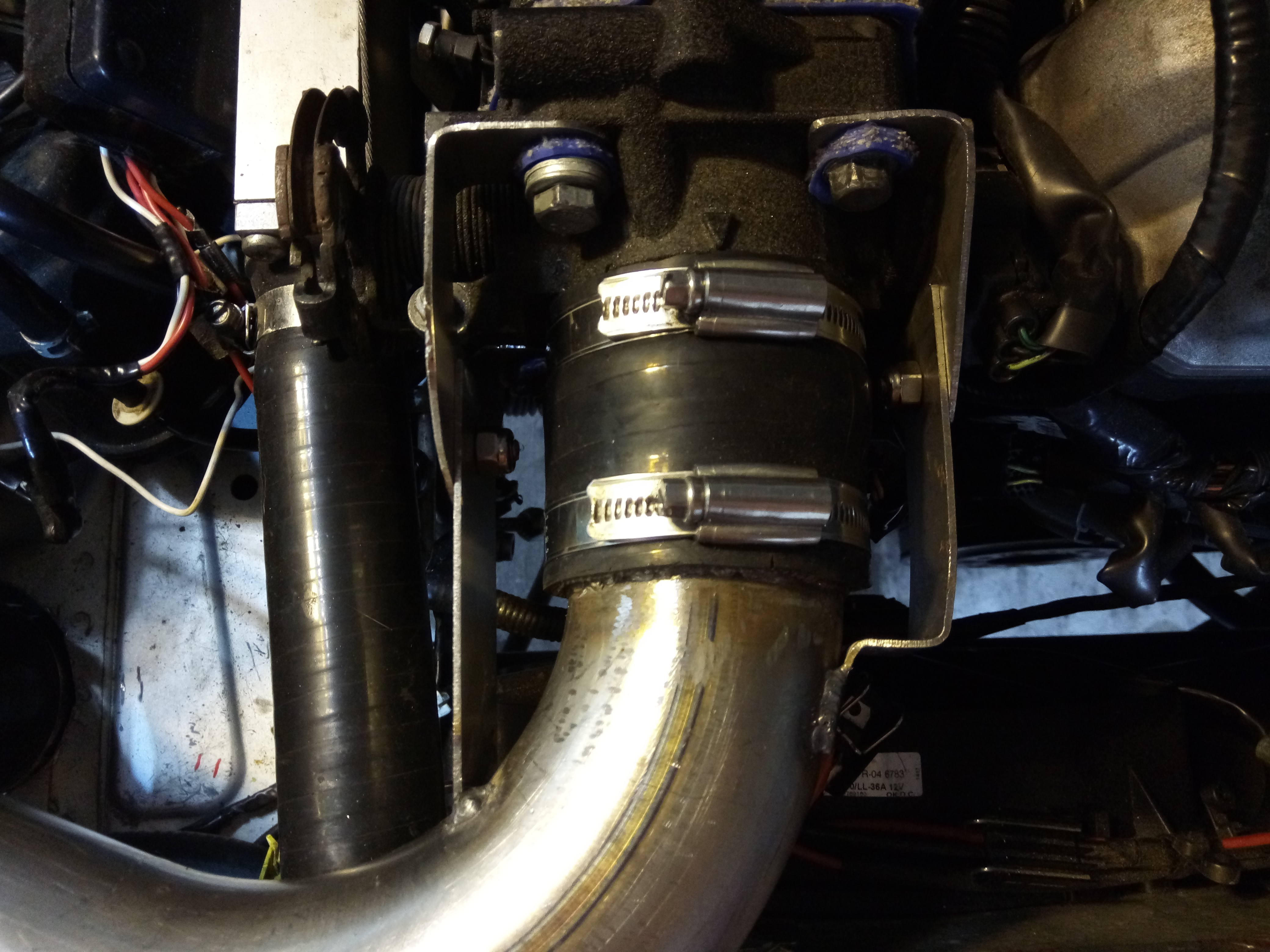
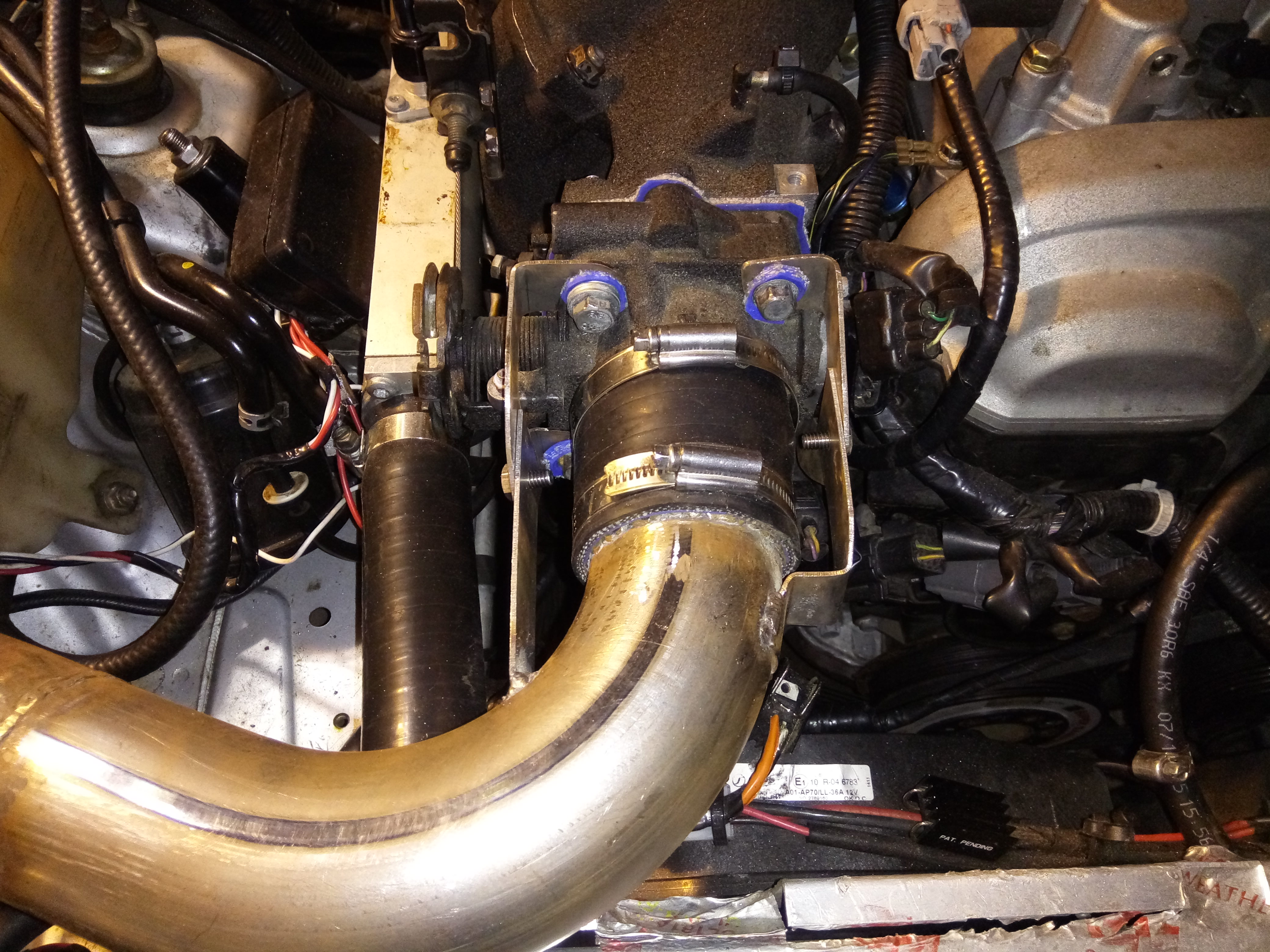
The bracing for the connections is made for the throttle body connection, and the passenger side connection. Only one left is for the intercooler connections, then that is done. Then I gotta build a downpipe, and some little stuff.
The bracing for the connections is made for the throttle body connection, and the passenger side connection. Only one left is for the intercooler connections, then that is done. Then I gotta build a downpipe, and some little stuff.
Reply
0
0

Thread Starter
Elite Member
iTrader: (16)
Joined: Aug 2007
Posts: 9,406
Total Cats: 559
From: Houston, TX
Ok Good news, PICS!!!
All the intercooler piping is built, just needs to be cleaned/painted and then reinstalled. I cut/modified/rewelded/painted my downpipe to fit the EFR turbo.
Quick question, are all the "B frame" EFR turbos swapable? AKA I could swap the 7670 for a 8374?
Back to my build, tomorrow I need to attempt to install my oil drain flange onto EFR, if it fits make a new gasket for it. Oil feed is done already. Reinstall downpipe and O2 sensor. Pull boost pipes and clean/reinstall them as oil probably poured in them from turbo failure, gotta pull them to check and clean. Clean/paint intercooler pipes, probably wrinkle black or just black. Bolt EFR wastegate shut as I'm using my external gate. Plumb EFR BOV and external BOV vacuum hoses. Hook up boost pipe to EFR inlet. Remove/clean EFR compressor as it's a bit dusty from sitting. Find fittings I think I bought for the EFR, and install them for water cooling.
Lot of little things, but the big stuff is done.
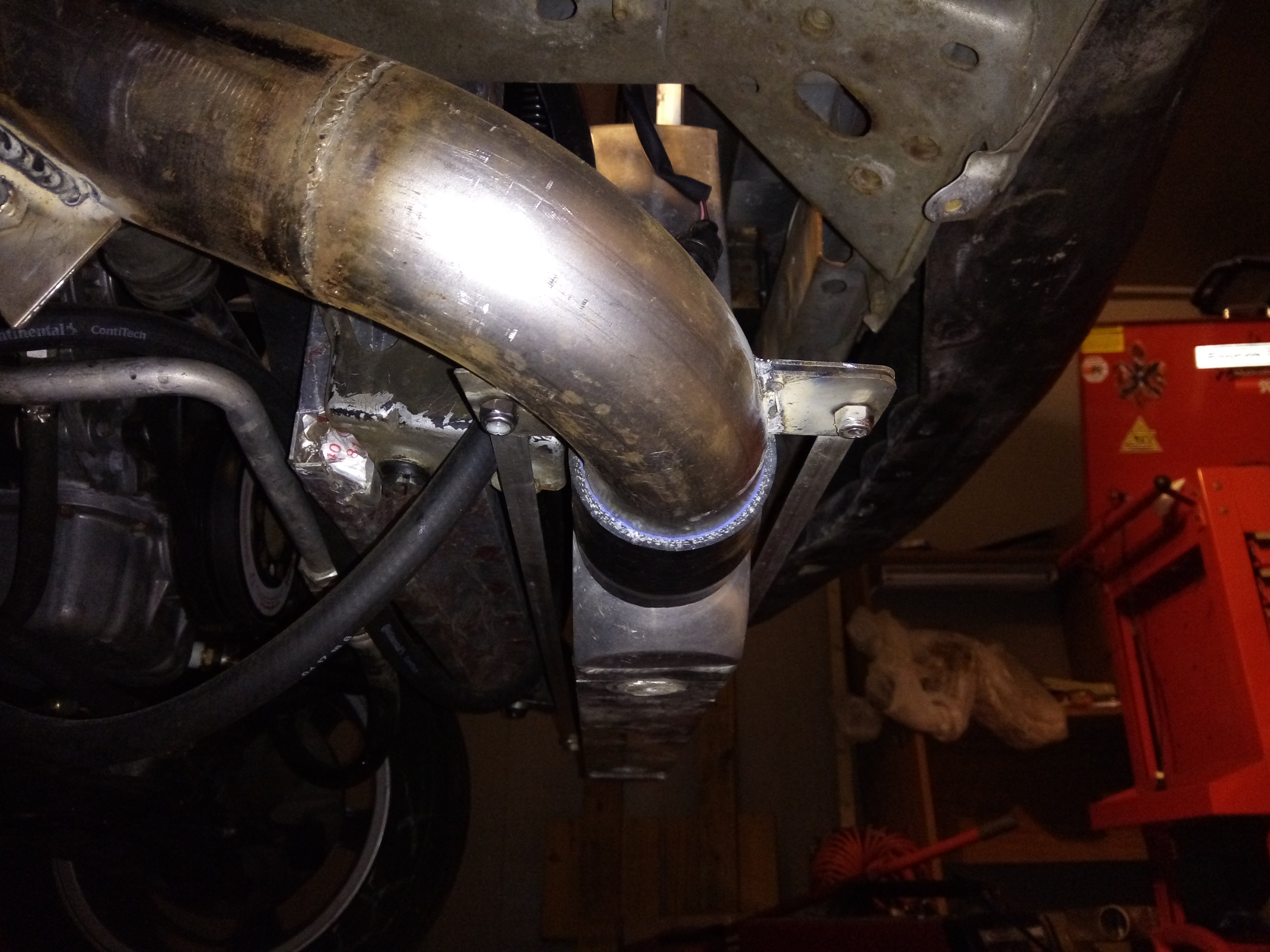
Reply
0
0

Thread Starter
Elite Member
iTrader: (16)
Joined: Aug 2007
Posts: 9,406
Total Cats: 559
From: Houston, TX
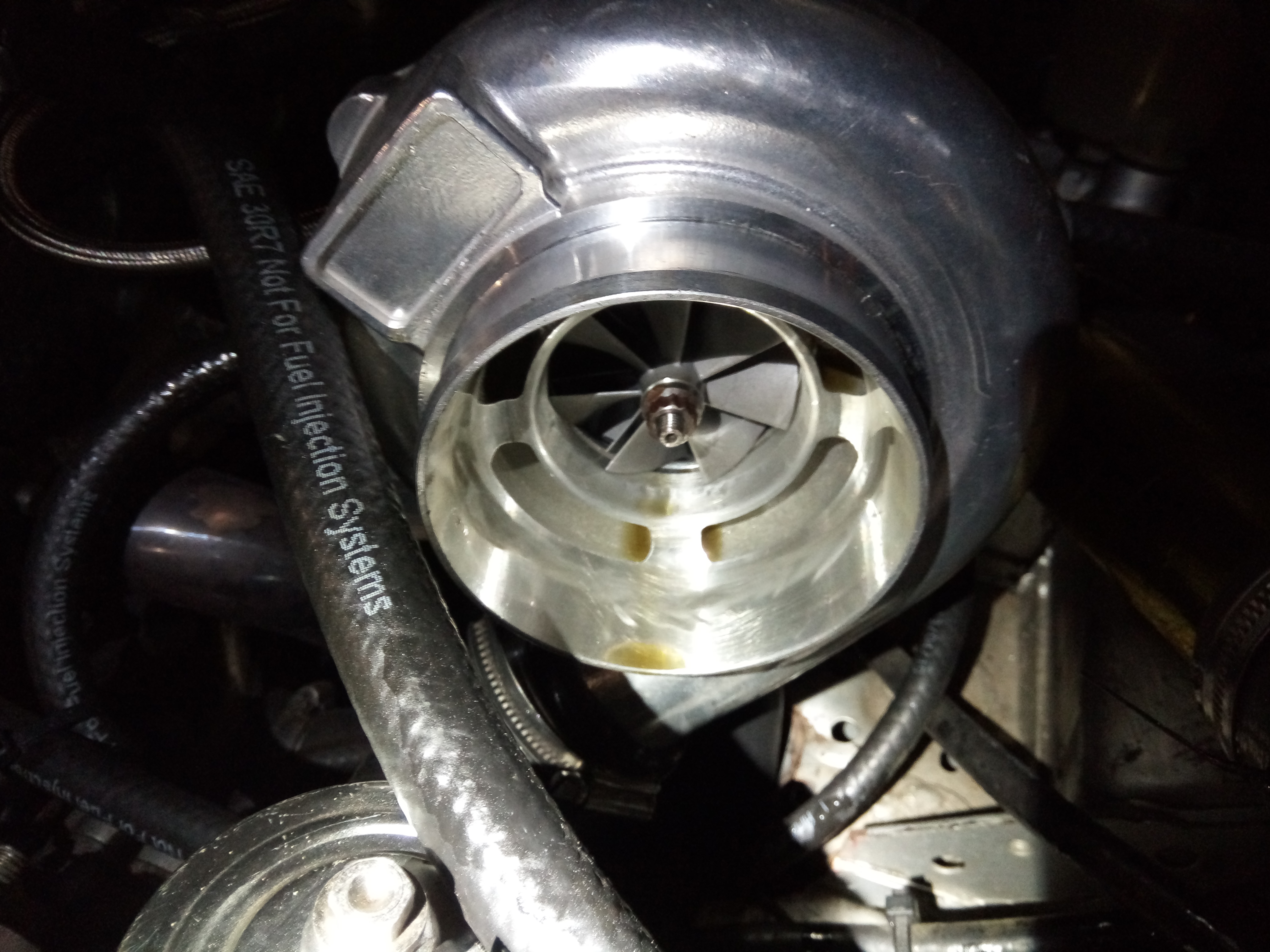
Intercooler pipes removed, welded a small metal pipe on it to replace a fitting I previously used to go to my wastegate so it doesn't poke in the pipe, and can't back out either. Also welded a 3/8 NPT threaded bung in so that when the AIT sensor goes in, it seals well and also only pokes in as needed, not too much. Finished welding some tabs, cleaned and painted the pipes wrinkle black. They are drying now. They look very nice.
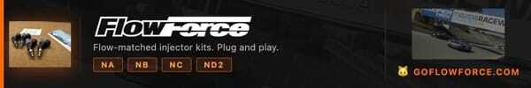
Turbo removed, taken apart, cleaned, dang that compressor wheel looks baller. I compared it to the ebay wheel. LOL I should have taken pics of them side by side, it's comical how different the designs are. Turbo reassembled. Oil drain flange removed from old turbo, new gasket made, installed. Made a high boost wastegate actuator and installed that on the EFR. Some here can probably imagine what that looks like. Turbo installed on manifold with a bit of some RTV that's supposedly good for exhaust parts. Almost all my V-bands leak a bit, so gonna do a light flim on everything and hope it seals everything.
Also checked and the boost control solenoid on the EFR leaks air if you don't use it, so I removed it. Going to block off the port that went to it before.
I swear I did more, but can't remember.
Not related to any of the above, but I'm thinking of making a new muffler for the car. Never made a muffler, kinda want to do it for fun and to see if I can design and build one that works well and sounds good.
Turbo removed, taken apart, cleaned, dang that compressor wheel looks baller. I compared it to the ebay wheel. LOL I should have taken pics of them side by side, it's comical how different the designs are. Turbo reassembled. Oil drain flange removed from old turbo, new gasket made, installed. Made a high boost wastegate actuator and installed that on the EFR. Some here can probably imagine what that looks like.
Turbo installed on manifold with a bit of some RTV that's supposedly good for exhaust parts. Almost all my V-bands leak a bit, so gonna do a light flim on everything and hope it seals everything. Also checked and the boost control solenoid on the EFR leaks air if you don't use it, so I removed it. Going to block off the port that went to it before.
I swear I did more, but can't remember.
Not related to any of the above, but I'm thinking of making a new muffler for the car. Never made a muffler, kinda want to do it for fun and to see if I can design and build one that works well and sounds good.
Reply
0
0

Elite Member
Joined: Apr 2010
Posts: 2,826
Total Cats: 66
From: Newcastle, Australia
You have to weld the V-Band on with it clamped to its matching half, clocked as it will be installed, this way they warp together, if you get the cheap ones which the pipe slips right through you can make it a slip joint by poking the pipe halfway through the other clamp.
Dann
Dann
Reply
0
0

You have to weld the V-Band on with it clamped to its matching half, clocked as it will be installed, this way they warp together, if you get the cheap ones which the pipe slips right through you can make it a slip joint by poking the pipe halfway through the other clamp.
Dann
Dann
Reply
0
0
Thread Starter
Elite Member
iTrader: (16)
Joined: Aug 2007
Posts: 9,406
Total Cats: 559
From: Houston, TX
Thanks guys, I didn't do any of those things so that explains why all my V-bands warped to hell. If the sealant doesn't work, I may just buy new v-bands, cut these off, and redo them the way you described so they won't warp.
Reply
0
0

Thread Starter
Elite Member
iTrader: (16)
Joined: Aug 2007
Posts: 9,406
Total Cats: 559
From: Houston, TX
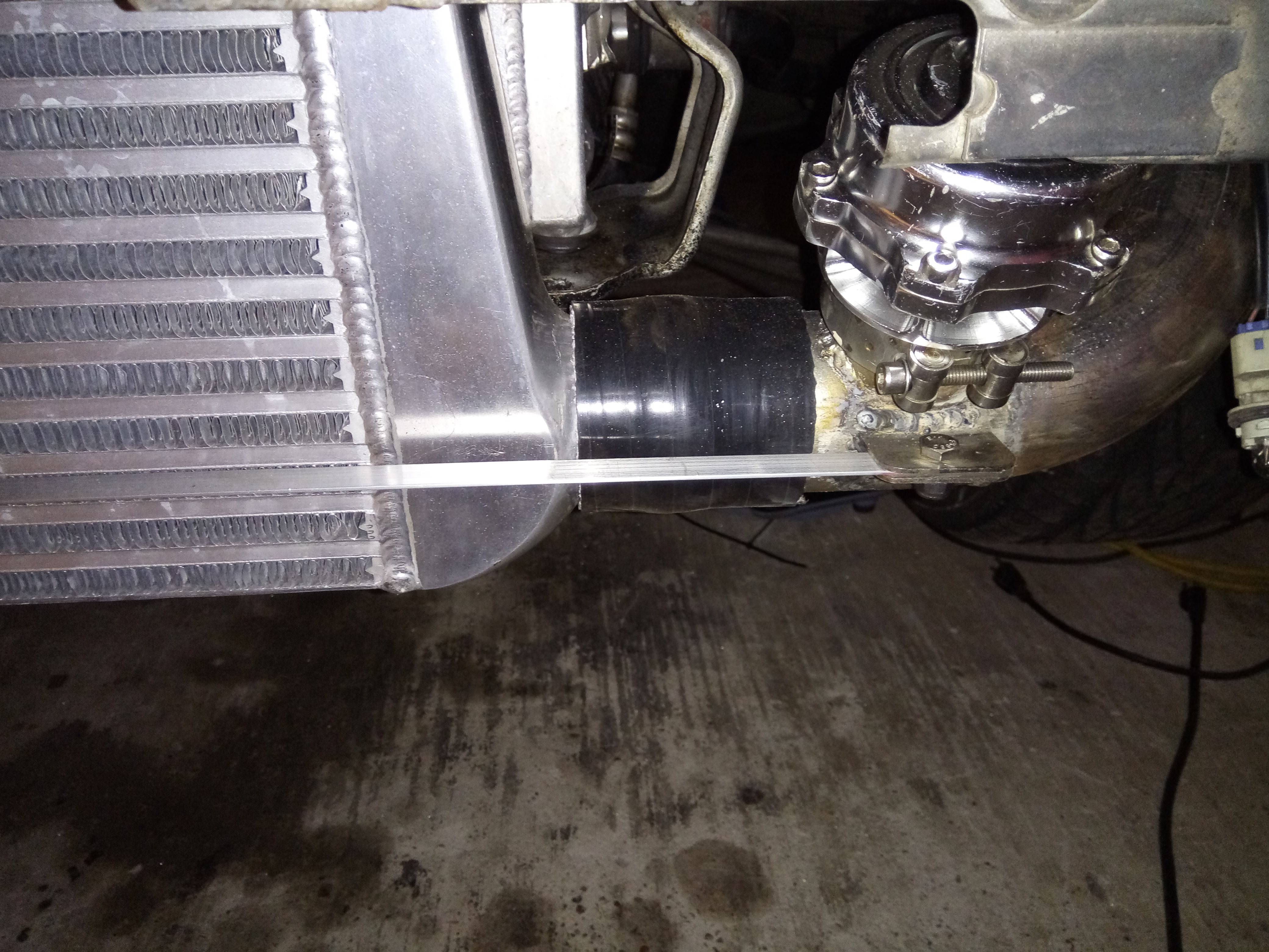
Above 30 PSI, I've struggled with keeping the pipes from popping off or not leaking. I've wanted to do the bracing to carry the load for years, since I saw it mentioned in Corky's book. Finally did it, very glad I did as I don't expect the braced connections to ever pop off unless the bracing itself fails for some reason.
Reply
0
0

So this might seem like a silly question to ask in this build thread but. Doesnt using that huge front turbo kind of defeat the purpose of the setup you've made here? I mean that big EFR probably wont hit peak boost on its own until over 4k. Of course it also means you probably have 800-1khp worth of airflow in your turbo setup now.
Reply
0
0
Thread Starter
Elite Member
iTrader: (16)
Joined: Aug 2007
Posts: 9,406
Total Cats: 559
From: Houston, TX
So this might seem like a silly question to ask in this build thread but. Doesnt using that huge front turbo kind of defeat the purpose of the setup you've made here? I mean that big EFR probably wont hit peak boost on its own until over 4k. Of course it also means you probably have 800-1khp worth of airflow in your turbo setup now.
My guess is the front turbo can easily do 500-550whp on its own, possibly more. I don't know how reliable it would be running at say, 40 PSI on its own though. Keeping it compound I can split the load on each turbo for a reduction in stress on the front one.
Reply
0
0

Reply
0
0

I'd also be really curious to see testing results of this thing with and without the rear turbo. Correct me if I'm wrong, but IIRC the best "quarter mile trap" as calculated by an online 1/8 to 1/4 mile calculator working from your best 1/8 trap speed is 130ish mph...right?
Reply
0
0


