When you click on links to various merchants on this site and make a purchase, this can result in this site earning a commission. Affiliate programs and affiliations include, but are not limited to, the eBay Partner Network.
Haha, wait I thought you built folks the MS3X? And yeah, I had you add the knock module to it.
I'll check the trubokittehhh site out and read there. Some of this wiring is beyond me right now re: adding power/ground/tach. I'm not sure if I'm just supposed to strip the existing cables for ground/tach and splice in the wires for the gauges. That seemed sketch, but wtf do I know. Or if I'm supposed to solder the wires to the open spots on the open slots of the connector.
MS3 simply denotes that it is using the MS3 board in it. The X part of MS3X means it is using the official expander board. The MS3labs ECU's by reverent use the MS3 board, and then he builds his own expander board with his own circuits. The MS3Pro's use the MS3 chipset on a custom circuit board that DIY designed. It has all the same circuits as the expander board, but laid out differently and a few are upgraded.
Some of this wiring is beyond me right now re: adding power/ground/tach. I'm not sure if I'm just supposed to strip the existing cables for ground/tach and splice in the wires for the gauges. That seemed sketch, but wtf do I know. Or if I'm supposed to solder the wires to the open spots on the open slots of the connector.
I built it for you so you wouldn't have to do all that, just follow the installation section.
I built it for you so you wouldn't have to do all that, just follow the installation section.
I'm not thatttt daft!
I'm asking about power and ground for aftermarket gauges like a boost gauge.
The wiring for the wideband was easy peasy thanks to you! I'm just trying to figure out:
1) How I get a tach signal to an aftermarket gauge, which in this case is an innovate boost gauge with a rpm shift light/tach indicator.
2) How do I ground these gauges to the MS3, which is what I read on MT is what I'm supposed to be doing.
re: powering gauges, I was going to use an add a circuit fuse.
Thanks for answering brain, I really appreciate it. I understandably don't want to **** things up lol.
MS3 simply denotes that it is using the MS3 board in it. The X part of MS3X means it is using the official expander board. The MS3labs ECU's by reverent use the MS3 board, and then he builds his own expander board with his own circuits. The MS3Pro's use the MS3 chipset on a custom circuit board that DIY designed. It has all the same circuits as the expander board, but laid out differently and a few are upgraded.
Ah that makes sense. So I have the same features that the X would have, but there was a different board used so it technically isn't an X in terms of hardware, but pretty much is in terms of functionality.
I'm asking about power and ground for aftermarket gauges like a boost gauge.
The wiring for the wideband was easy peasy thanks to you! I'm just trying to figure out:
1) How I get a tach signal to an aftermarket gauge, which in this case is an innovate boost gauge with a rpm shift light/tach indicator.
2) How do I ground these gauges to the MS3, which is what I read on MT is what I'm supposed to be doing.
re: powering gauges, I was going to use an add a circuit fuse.
Thanks for answering brain, I really appreciate it. I understandably don't want to **** things up lol.
1. tap off the green orange wire.
2. depends on the ground it asks for -- you can wire it back to same ground as your wbo2 if it says a power ground.
1. tap off the green orange wire.
2. depends on the ground it asks for -- you can wire it back to same ground as your wbo2 if it says a power ground.
Oh snap, I didn't know T-tap connectors were a thing so I don't even have to cut into the wire to get the signal, eh? Cool. I thought I was going to have to splice things for the tach.
Re: Ground, just splice whatever ground wires into the wire I used butt connectors on in accordance with your ms3 instructions. Got it.
Thanks for the help!
"Tap" is a concept, meaning "to draw from". It does not mean to use an in-approppriate method to do so. T-Tap's are an example of an inappropriate method.
Ah that makes sense. So I have the same features that the X would have, but there was a different board used so it technically isn't an X in terms of hardware, but pretty much is in terms of functionality.
If you purchased your MS from Braineack then you have an MS3X.
This is the MS3 chip board. All MS3* variants use this board in someway shape or form.
This is the Expander board or the X in MS3X. It is a secondary board that provides you with all the awesome circuits that give you all the neat feature the MS3 can do. Like the 8 injector and spark circuits, VVT, IDLE, Tach, Cam in, and so on and so forth. You can theoretically build all these circuits yourself and get the same features without this board. It is just a PITA and not documented well any more. The MS3X that Braineack sells uses this board. The MSLabs ecu's do not. Reverent basically builds this board on his own, in his own way. The MS3Pro's also do not use this board. They have their own similar designed one with a few circuits upgraded.
*The MS3Pro's also have a different board in general. It uses all the same circuits as the other boards except for a few upgraded. DIY just redesigned it to all fit on a single board to be easier for their production.
I mean the first PNP unit they sold was for the 1.6 Miata. Jeremy the owner has a turbo miata. And Ben one of their workers has been active on MT since forever.
"Tap" is a concept, meaning "to draw from". It does not mean to use an in-approppriate method to do so. T-Tap's are an example of an inappropriate method.
I agree with this 100%, Pick up a soldering iron - if needed i could probably assist this weekend as well.
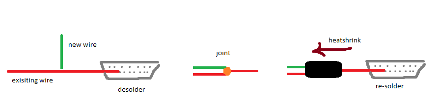
I do like the idea of basically cutting the wire, then using a butt-end crimp to put it back together with two wires going in on one side. Probably the easiest/quickest way to do it as well. I like the crimps with integrated heatshrink, but you need to make sure you get a really good crimp on these, you wouldn't want your power wire to fall out.
Last edited by Braineack; Feb 17, 2017 at 12:20 PM.
I agree with this 100%, Pick up a soldering iron - if needed i could probably assist this weekend as well.
I have one. I just wanted to get things right. Like I said, I'm pretty sure I can do whatever is asked of me, but I wanted to be sure I'm not missing something. I'm always up for having someone teach me how to do things the right way though!
but, id honestly tap into the radio harness for pwr/ground for my gauges... that's what i did with my 3-gauge pod in the dash.
****. This thread didn't turn up in search. I should have used the gauge model number instead of name to search.
And I actually do want to use the radio wires, but it's a rats nest back there and I'm intimidated by it. I guess I should disconnect my battery and get to work a ton of wires that are taped up behind there and actually crimp them up properly.
Originally Posted by aidandj
Nope. Skip the soldering iron too. Crimps ftw. I like uninsulated butt crimps with heat shrink.
Yessir. That was the plan. I just wanted to make sure that I wasn't missing a way of doing things in a way that didn't involve cutting the tach output to the dash in order to get a second signal in there. I don't want to cut up the megasquirt power cable, but I guess I'm going to have to do that for the ground. I'm guessing it isn't 'good enough' to just ground to a screw or something back behind the radio. I can always run a ground wire to one of the bolts on the valve cover or something for everything since I don't want to cut up the wires for the MS3.
That's what you meant by getting ground for the MS3 right? Tapping into the ground wire? Or were you suggesting running a wire to one of the open pin slots on the harness? I'm not sure how I'd make that one a ground since the unused slots don't really have connections inside.
If you purchased your MS from Braineack then you have an MS3X.
This is the MS3 chip board. All MS3* variants use this board in someway shape or form.
This is the Expander board or the X in MS3X. It is a secondary board that provides you with all the awesome circuits that give you all the neat feature the MS3 can do. Like the 8 injector and spark circuits, VVT, IDLE, Tach, Cam in, and so on and so forth. You can theoretically build all these circuits yourself and get the same features without this board. It is just a PITA and not documented well any more. The MS3X that Braineack sells uses this board. The MSLabs ecu's do not. Reverent basically builds this board on his own, in his own way. The MS3Pro's also do not use this board. They have their own similar designed one with a few circuits upgraded.
*The MS3Pro's also have a different board in general. It uses all the same circuits as the other boards except for a few upgraded. DIY just redesigned it to all fit on a single board to be easier for their production.
Thanks for this awesome explanation.
Can this be added to the sticky on the MS subforum?


 0
0