Retrofit ABS into NB
 08-25-2013, 03:25 PM
#21
Elite Member

Thread Starter
Join Date: Mar 2007
Location: Santa Clara, CA
Posts: 5,167
Total Cats: 856
I did most of the rest of the electrical wiring for the ABS unit yesterday. Since I'd cut off the sensors in the wrong place, the two wires I was splicing to were not keyed and the same color. I'm told that, theoretically, reluctors should give a sawtooth waveform, but looking at it on an oscilloscope while spinning the wheel by hand the slope of the rising and falling edges looked pretty much the same so I'm not sure it matters. No shots of the waveform though, sorry.
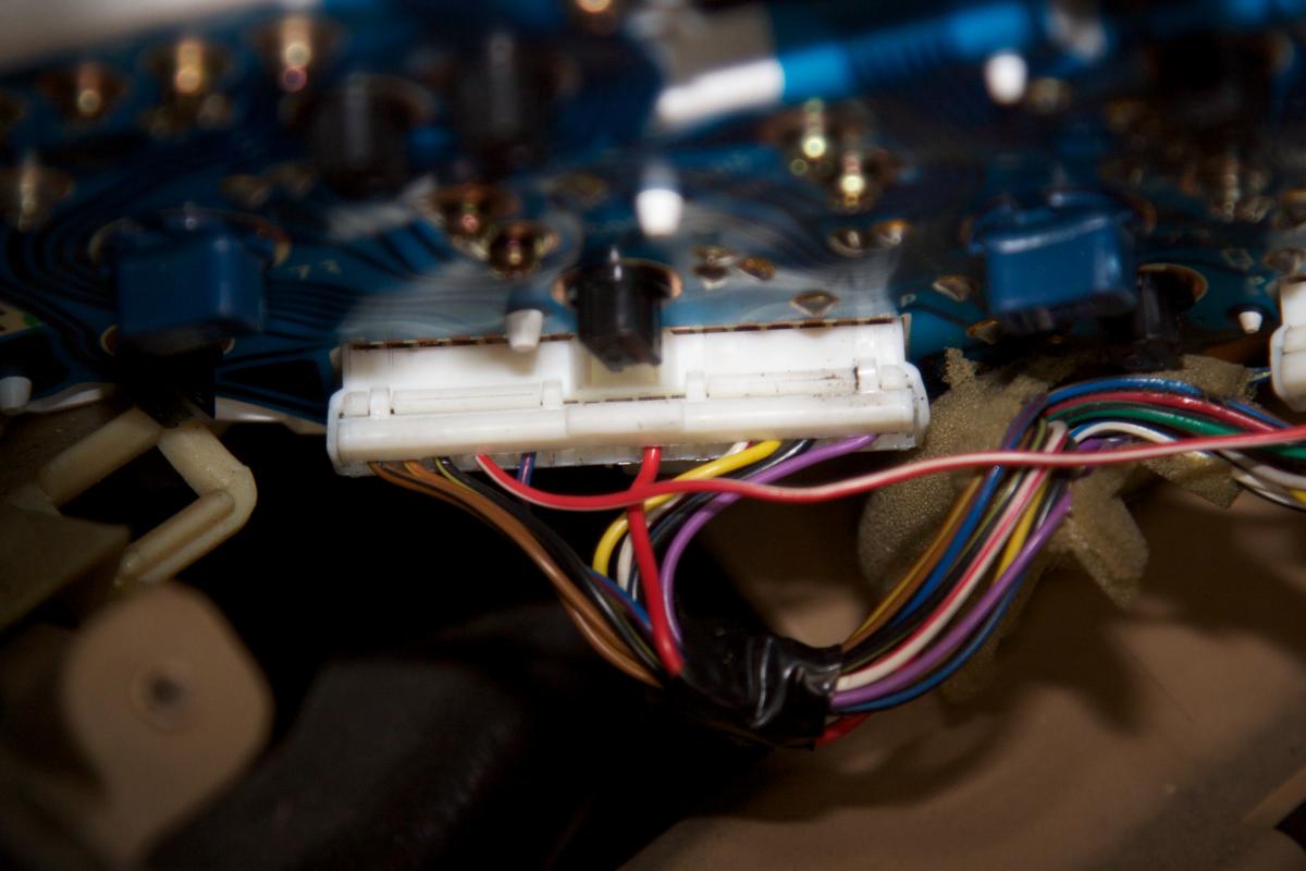
As I discovered previously, my 99 instrument cluster has an ABS light in it, but there's no wire for it in the factory harness. To deal with that, I got a piece of the harness from another car and stole a pin + pigtail wire out of it. The connector shell pops open and the pins come out with a bit of poking.
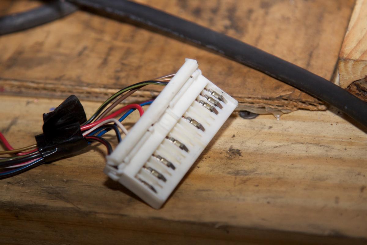
The car it came from was a non-ABS automatic, so I used the "OD off" pin just because that gave me a unique wire color (red/white), even if it wasn't the right one for the ABS light (pink/black). Had to buy all 3 connectors from the salvage yard, and they charged way too much for, now I've got a huge pile of extra pins if anyone wants one.
It also turns out that the 10 amp ABS fuse power for the electronics that I thought was present in the under-dash fusebox is not there, I must have been smoking crack when I looked at it before. Given that, I decided to just pull all the power and ground next to the ABS hydraulic unit and avoid running additional wires around.
The 20 amp ABS fuse power for the solenoids *is* present in the engine bay fusebox. The 99 fusebox is kind of a strange contraption, it's in two pieces, with wiring connectors in both parts. The 20 amp ABS fuse is connected to a wire in the stub harness that goes between the two parts, but again the pin is missing in the factory harness. I just cut that wire in the stub harness and spliced it over to the hydraulic unit.
The ABS pump power is listed in the wiring diagram as a fusible link with no current rating shown. Since it appears to be 10 or 12 gauge wire in the harness, I decided to go with a 50 amp fuse. Currently that's just hacked up.
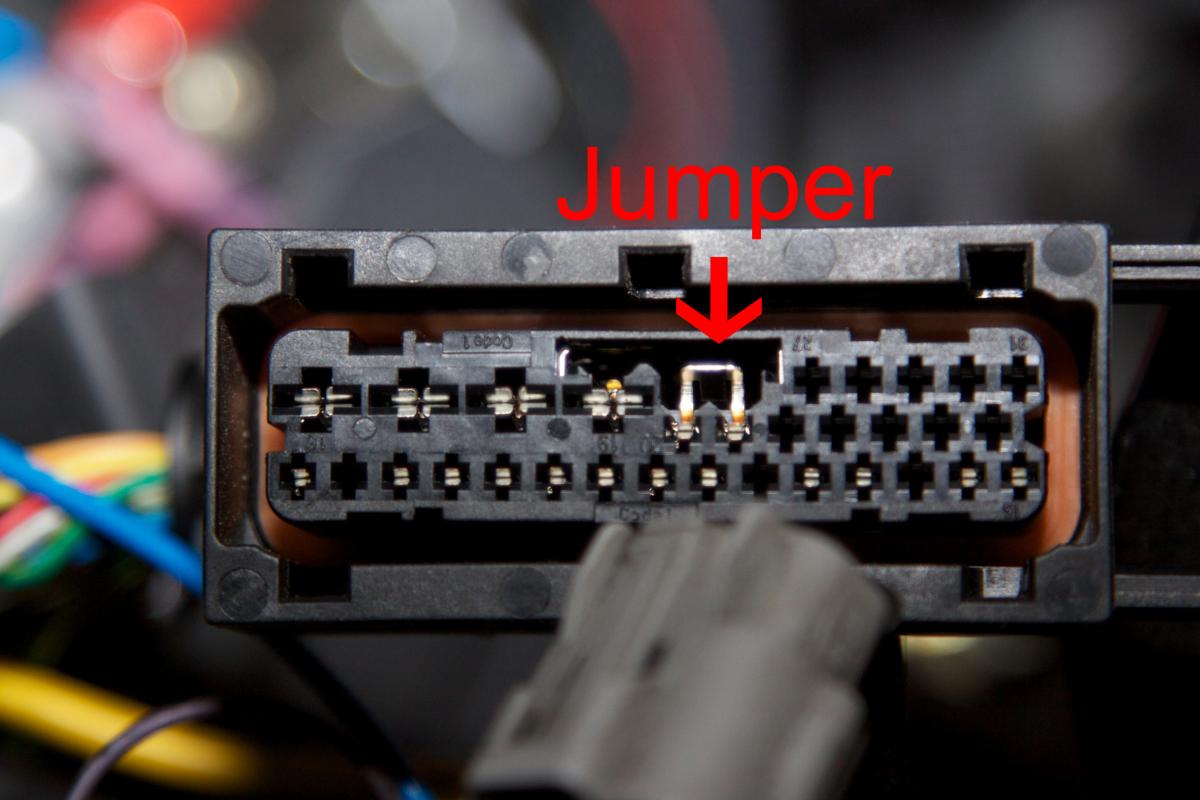
So I hooked it all up and did a power-on test with the hydraulic unit disconnected to look for magic smoke coming out. No smoke, but both the ABS light and regular brake light were illuminating on the instrument cluster. After poking around a bit, it turns out that those clever German engineers at Bosch designed the ABS connector so that if it's not connected then a springloaded jumper comes down and connects both of those pins to ground to turn the lights on so that you'd know something was wrong. I plugged it back in and the brake light went out.
So now it's powering up and doing the same "512" blink code that it did when we tested it on the bench. I still can't find a list of what the codes mean for it, but I guess 512 isn't "no ABS wheel sensor", since it's got those now. Hopefully it means "no pressure in the pump" and that will fix itself once I've got the hydraulics connected, rather than "I'm completely fried and not working".
--Ian
As I discovered previously, my 99 instrument cluster has an ABS light in it, but there's no wire for it in the factory harness. To deal with that, I got a piece of the harness from another car and stole a pin + pigtail wire out of it. The connector shell pops open and the pins come out with a bit of poking.
The car it came from was a non-ABS automatic, so I used the "OD off" pin just because that gave me a unique wire color (red/white), even if it wasn't the right one for the ABS light (pink/black). Had to buy all 3 connectors from the salvage yard, and they charged way too much for, now I've got a huge pile of extra pins if anyone wants one.
It also turns out that the 10 amp ABS fuse power for the electronics that I thought was present in the under-dash fusebox is not there, I must have been smoking crack when I looked at it before. Given that, I decided to just pull all the power and ground next to the ABS hydraulic unit and avoid running additional wires around.
The 20 amp ABS fuse power for the solenoids *is* present in the engine bay fusebox. The 99 fusebox is kind of a strange contraption, it's in two pieces, with wiring connectors in both parts. The 20 amp ABS fuse is connected to a wire in the stub harness that goes between the two parts, but again the pin is missing in the factory harness. I just cut that wire in the stub harness and spliced it over to the hydraulic unit.
The ABS pump power is listed in the wiring diagram as a fusible link with no current rating shown. Since it appears to be 10 or 12 gauge wire in the harness, I decided to go with a 50 amp fuse. Currently that's just hacked up.
So I hooked it all up and did a power-on test with the hydraulic unit disconnected to look for magic smoke coming out. No smoke, but both the ABS light and regular brake light were illuminating on the instrument cluster. After poking around a bit, it turns out that those clever German engineers at Bosch designed the ABS connector so that if it's not connected then a springloaded jumper comes down and connects both of those pins to ground to turn the lights on so that you'd know something was wrong. I plugged it back in and the brake light went out.
So now it's powering up and doing the same "512" blink code that it did when we tested it on the bench. I still can't find a list of what the codes mean for it, but I guess 512 isn't "no ABS wheel sensor", since it's got those now. Hopefully it means "no pressure in the pump" and that will fix itself once I've got the hydraulics connected, rather than "I'm completely fried and not working".
--Ian

Reply
 0
0

0
08-25-2013, 04:22 PM
#23
Elite Member
Thread Starter
Join Date: Mar 2007
Location: Santa Clara, CA
Posts: 5,167
Total Cats: 856
The ABS light. In the bench test, it's clearly 5 short blinks, 1 long blink, 2 short blinks, then it repeats. I just went out and video'd the in-car one, and there it appears that it might be 2 short, 5 short, 1 long. So maybe that's 25? I dunno.
Bench test:
In-car:
--Ian
Bench test:
In-car:
--Ian
Reply
0
0
08-28-2013, 05:13 AM
#26
Elite Member
Thread Starter
Join Date: Mar 2007
Location: Santa Clara, CA
Posts: 5,167
Total Cats: 856
So I installed the booster & master cylinder tonight, and ran some of the brake lines. The 2003 line to the passenger front wheel isn't going in without taking the intake manifold out, so I'm going to splice that one too.
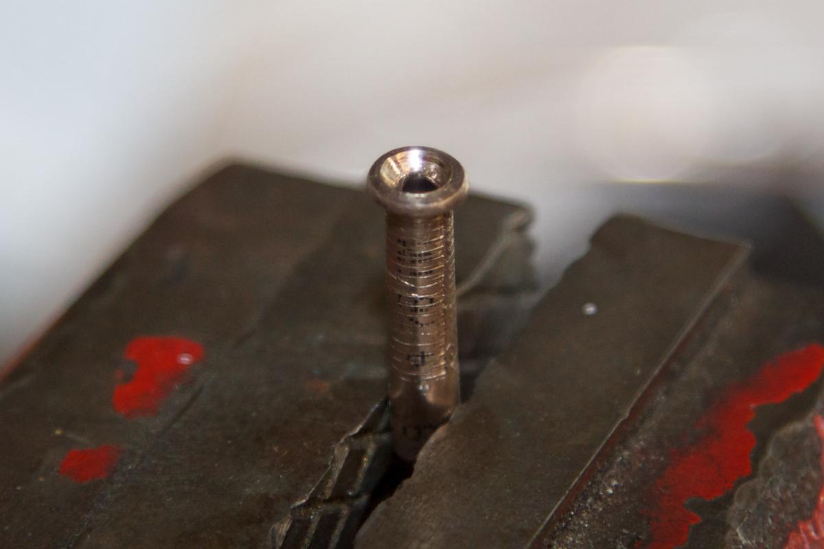
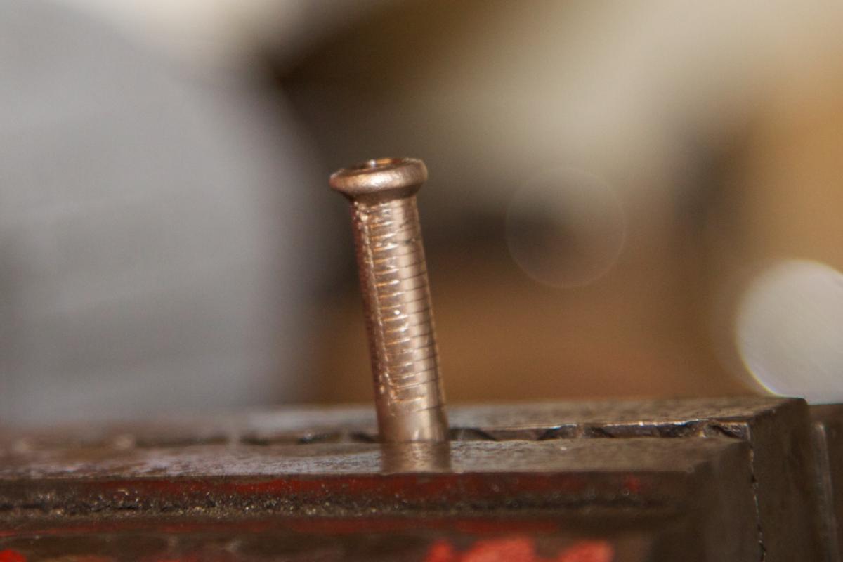
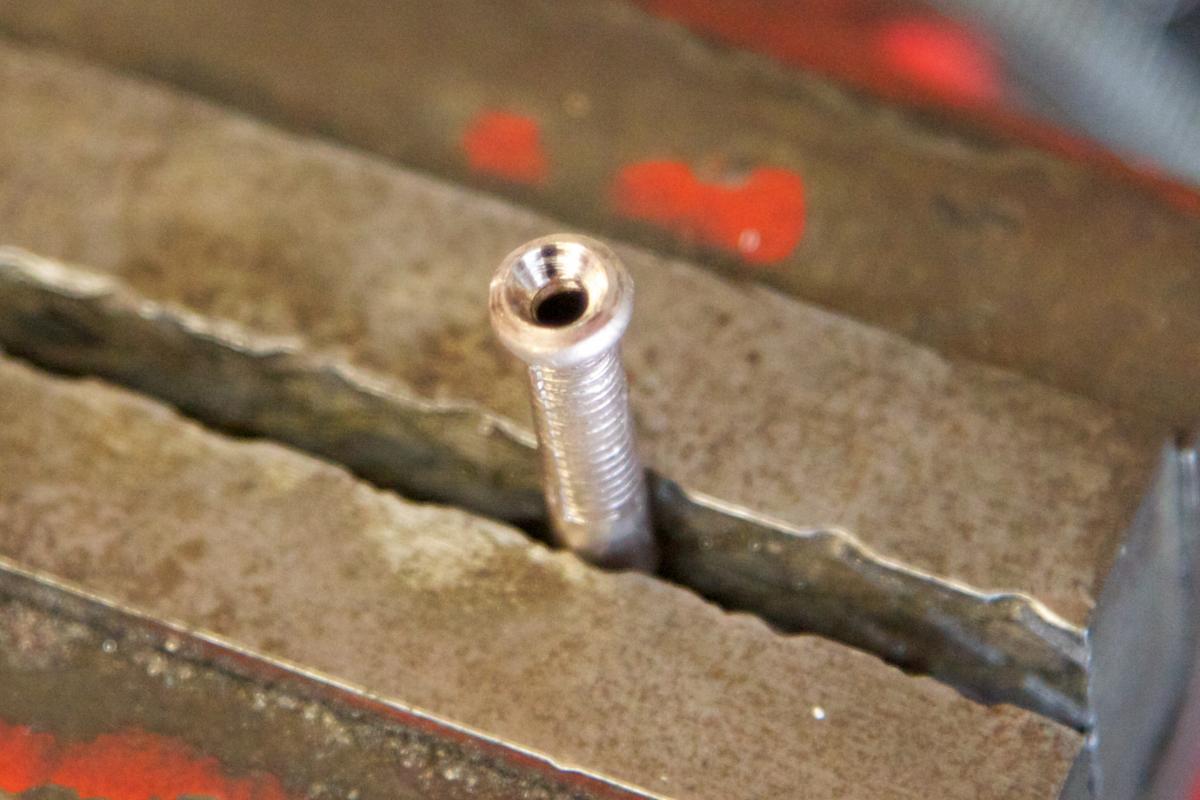
Before cutting the factory lines, I decided to test my flaring prowess with the cunifer lines. I hooked up the master, "prop valve", and the front & rear crossover lines to the ABS unit, ran a short cunifer jumper line between two of the ABS ports, hooked up the last one to a caliper, and put some pressure on it to see if it would seal.
Eventually it did, but I had to crank down on the cunifer lines quite a bit tighter than the factory ones. Is that expected, or do my flares just suck? Also, the factory lines go from loose to tight in maybe half a turn, whereas the cunifer ones seem to be 2-3 times that much.
Incidentally, the ABS unit still blinked the same codes with the hydraulics hooked up, but the ABS light isn't on when the diag line is disconnected (it comes on at power up, then goes off, as expected). So maybe that's not a trouble code after all, maybe that's just what it does when it's happy, I dunno. It doesn't seem to cycle the pump in any kind of self test when I power it up, either. I'll find out if it works once I get the hydraulics finished.
--Ian
Reply
0
0
08-28-2013, 05:54 AM
#27
Elite Member

Join Date: Mar 2008
Location: Enschede, NL
Posts: 2,053
Total Cats: 12
Post pics of your flares.
About the light: it appears you sometimes need to erase codes. That is: the light may be off in running mode, but it will still display (old?) codes when in diag mode.
Can't get the exact details about that one yet.
About the light: it appears you sometimes need to erase codes. That is: the light may be off in running mode, but it will still display (old?) codes when in diag mode.
Can't get the exact details about that one yet.
Reply
0
0

 08-30-2013, 01:12 PM
#31
Elite Member
iTrader: (15)

Join Date: Dec 2007
Location: San Antonio, Texas
Posts: 4,847
Total Cats: 27
So not to jack the thread, but I have a related DIY ABS install question I would like to pose... I have non-Miata rear outer CVs (V8 conversion related) that are too large to fit the rear Miata ABS ring. I think they are too large to where I could turn the i.d. on a stock ring and make it fit.
If I can make/fit a different toothed ring onto the shaft, could it be made to work? I would think if I changed the tooth pitch such that the pulse per revolution count was the same as stock, then maybe it would still work.
If I can make/fit a different toothed ring onto the shaft, could it be made to work? I would think if I changed the tooth pitch such that the pulse per revolution count was the same as stock, then maybe it would still work.
Reply
0
0
08-30-2013, 01:17 PM
#32
Elite Member
Thread Starter
Join Date: Mar 2007
Location: Santa Clara, CA
Posts: 5,167
Total Cats: 856
So not to jack the thread, but I have a related DIY ABS install question I would like to pose... I have non-Miata rear outer CVs (V8 conversion related) that are too large to fit the rear Miata ABS ring. I think they are too large to where I could turn the i.d. on a stock ring and make it fit.
If I can make/fit a different toothed ring onto the shaft, could it be made to work? I would think if I changed the tooth pitch such that the pulse per revolution count was the same as stock, then maybe it would still work.
If I can make/fit a different toothed ring onto the shaft, could it be made to work? I would think if I changed the tooth pitch such that the pulse per revolution count was the same as stock, then maybe it would still work.
If you can't turn the i.d. on the stock ring because there's not enough meat, then you probably need a ring with a larger o.d. That means you'll need to space the pickup outwards, and getting the right gap between it and the teeth is fairly important.
--Ian
Reply
0
0
08-30-2013, 01:24 PM
#33

If the mass difference of the teeth (thinner ring would make it really equal) matters I dunno, but if so it would be a stupidly sensitive system.
While you are at it, test to see if 20% +- teeth (on all four rings) would affect the calibration (if the allowed slip would increase).
I know too little about ABS calibration to know if the allowed slip is speed dependent in the NB units. If it is different changing rings would be the easiest way to change things (assuming rings gets made by someone).
But then there is the mix of sticky rubber and wet races, changing ABS rings between heats would be a hassle.
Reply
0
0
08-31-2013, 12:23 AM
#34
Elite Member
iTrader: (15)
Join Date: Dec 2007
Location: San Antonio, Texas
Posts: 4,847
Total Cats: 27
Yep agree on those points:
- Change the bracket to maintain the proper sensor spacing
- Cut a new one from steel with the same tooth count, same width, and the same ratio of tooth width to tooth gap. ABS computer won't know the difference.
It's worth a shot.
- Change the bracket to maintain the proper sensor spacing
- Cut a new one from steel with the same tooth count, same width, and the same ratio of tooth width to tooth gap. ABS computer won't know the difference.
It's worth a shot.
Reply
0
0
08-31-2013, 11:47 PM
#35
Elite Member
Thread Starter
Join Date: Mar 2007
Location: Santa Clara, CA
Posts: 5,167
Total Cats: 856
And... it works! We wound up managing to get the front right factory line installed after all, and only cut the rear line. Also didn't actually need the cunifer -- just bent the original line over 180 degrees so that it went to the passenger side instead of the driver's, cut a foot or so off the end, added a few more bends and a flare, and it went to the ABS unit. Having a bunch of spare line was useful for practicing the flares, though.
Need to bleed the system again and add some rubber hose as anti-abrasion in strategic portions of the new lines. More pictures forthcoming.
--Ian
Need to bleed the system again and add some rubber hose as anti-abrasion in strategic portions of the new lines. More pictures forthcoming.
--Ian
Reply
0
0
09-05-2013, 02:56 AM
#36
Elite Member
Thread Starter
Join Date: Mar 2007
Location: Santa Clara, CA
Posts: 5,167
Total Cats: 856
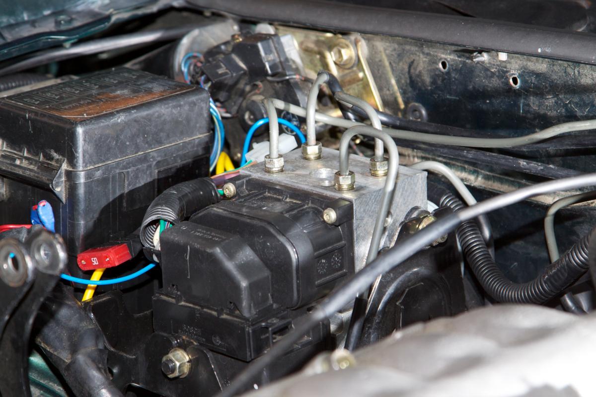
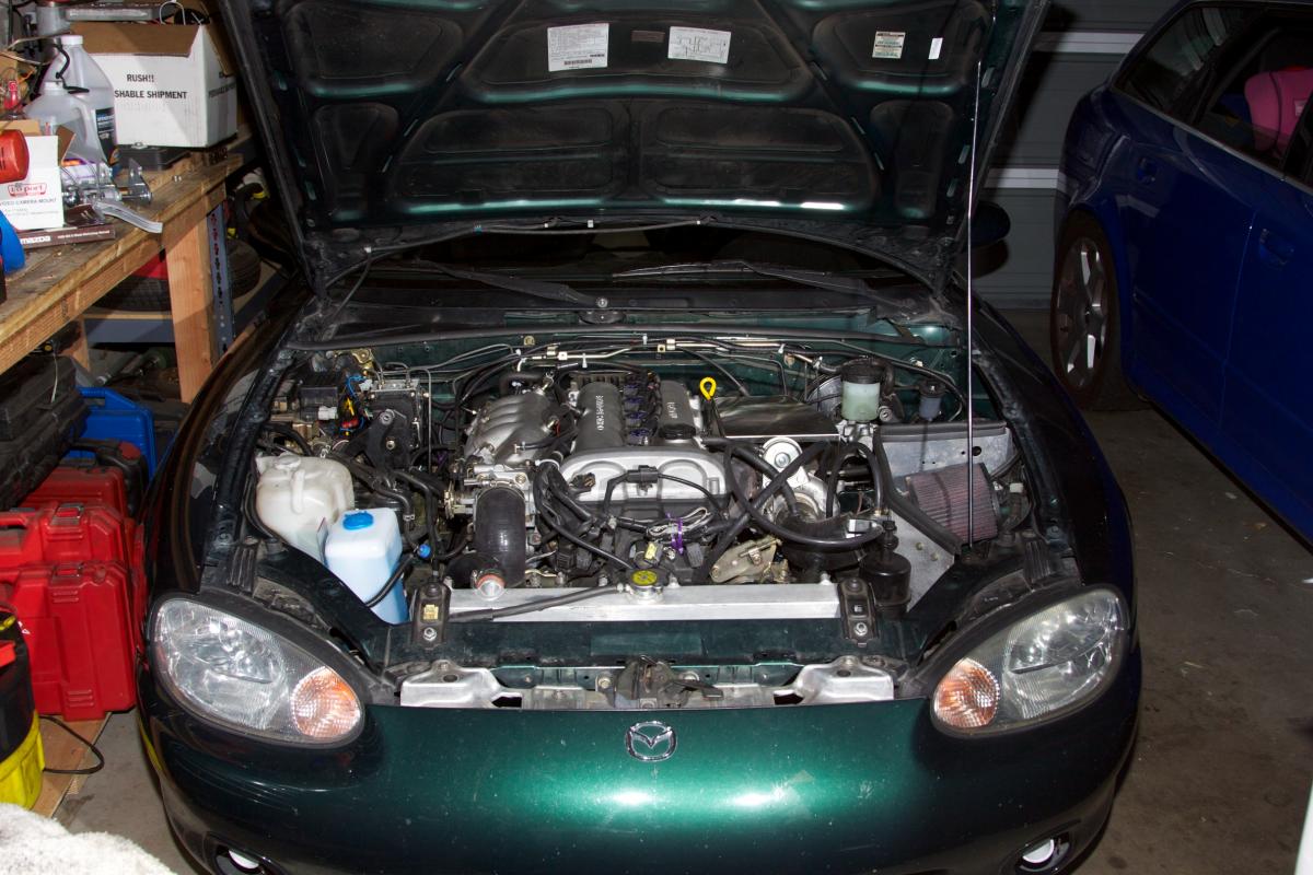
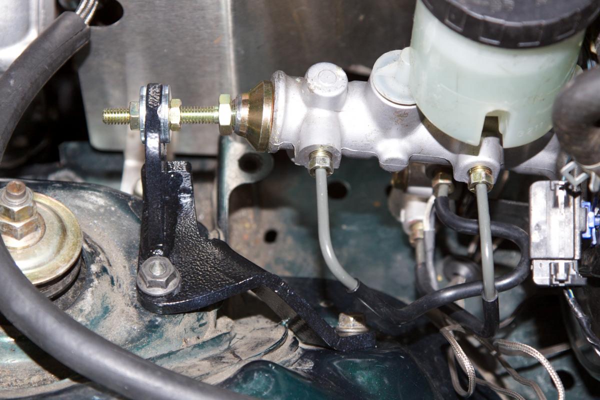
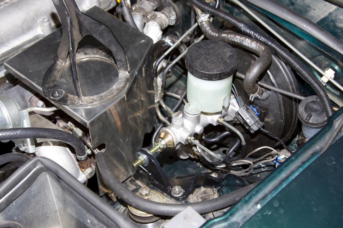
Some shots of the finished parts. Since we managed to fit the front right line in, and bend the rear line around to where it could be trimmed and flared, I avoided needing to splice stuff. As a result it looks mostly factory, which is not a bad thing.
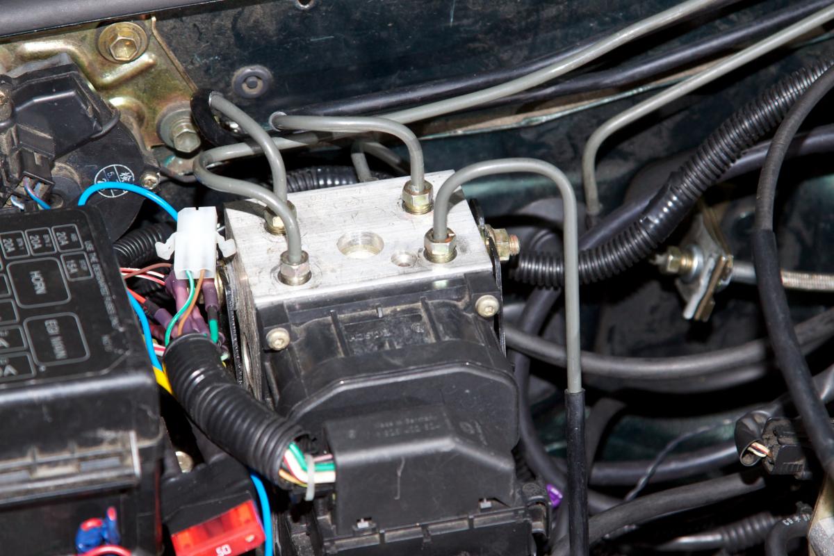
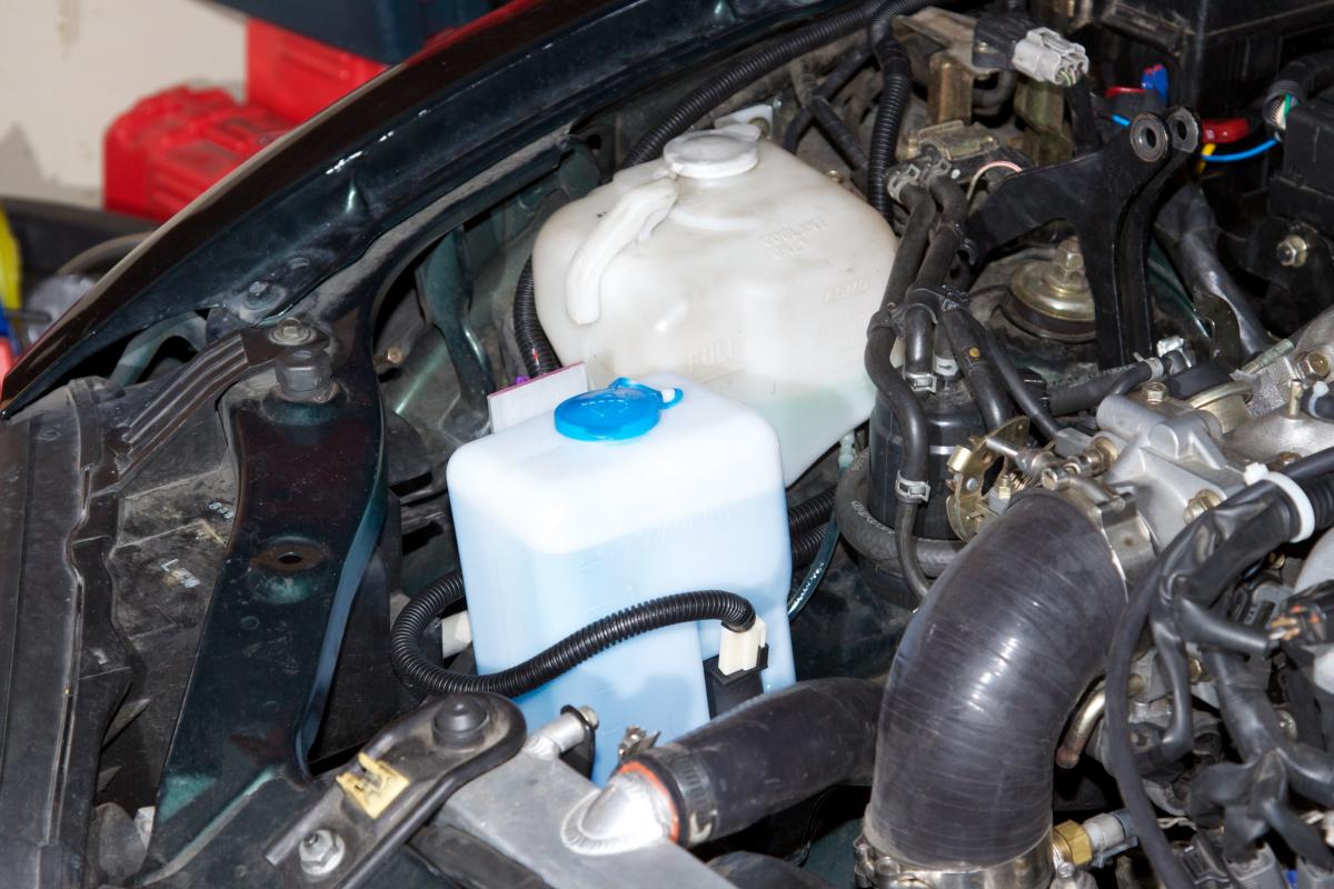
The rebent rear line is the one that runs along the firewall that has no black coating on it. I assume this is anti-abraision coating of some kind -- I still need to figure out what to add for that. Heat shrink might've been a good choice, but I didn't think of it until after I'd flared it, so I don't think it'd fit.
The windshield washer bottle installed:
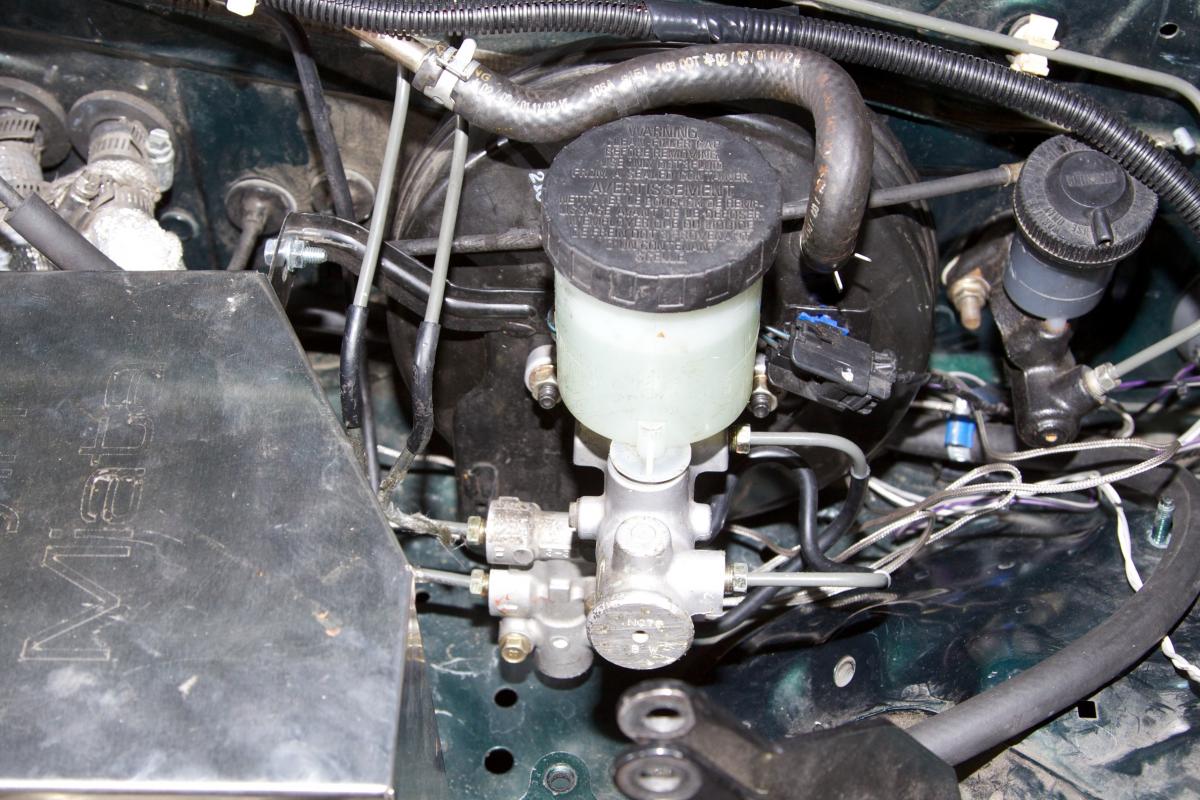
Master cylinder -- this is all factory piping:
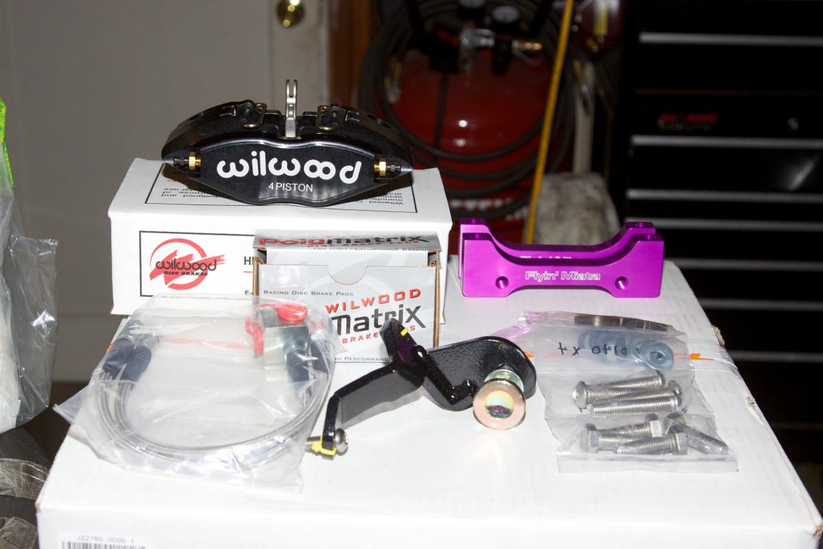
What's this? New toys from FM that just showed up? Alas, too late to install while I was bleeding/flushing the entire system. I sense I will need more brake fluid in the near future.
(Yes, I bought the pansy kit with a parking brake. I still drive this car to work every now and then, so I'll have to live with the extra 3 pounds).
This little guy was easy to install. Meant I had to take the old FM shock tower brace off, though. (Really old, it's has a sticker saying "Dealer Alternative" on it) It's supposed to fit with it, but not unless someone sells an NB shock hat that has studs about an inch longer than factory...
--Ian
The rebent rear line is the one that runs along the firewall that has no black coating on it. I assume this is anti-abraision coating of some kind -- I still need to figure out what to add for that. Heat shrink might've been a good choice, but I didn't think of it until after I'd flared it, so I don't think it'd fit.
The windshield washer bottle installed:
Master cylinder -- this is all factory piping:
What's this? New toys from FM that just showed up? Alas, too late to install while I was bleeding/flushing the entire system. I sense I will need more brake fluid in the near future.
(Yes, I bought the pansy kit with a parking brake. I still drive this car to work every now and then, so I'll have to live with the extra 3 pounds).
This little guy was easy to install. Meant I had to take the old FM shock tower brace off, though. (Really old, it's has a sticker saying "Dealer Alternative" on it) It's supposed to fit with it, but not unless someone sells an NB shock hat that has studs about an inch longer than factory...
--Ian
Reply
0
0
 09-05-2013, 10:12 AM
#38
The rebent rear line is the one that runs along the firewall that has no black coating on it. I assume this is anti-abraision coating of some kind -- I still need to figure out what to add for that. Heat shrink might've been a good choice, but I didn't think of it until after I'd flared it, so I don't think it'd fit.
Cable shielding is usually much easier to split in several feets length than hose.
Plastidip (if you want to remove the line)?
But for now I just use small pieces of hose and cable ties between the lines to give them some stability where they were close to each other.
Just to clarify, I have moved my NB1 ABS pump to the passenger footwell area. Meaning new lines to MC and fronts, and cut/join for the rears. Five lines through one of the AC FW holes.
Reply
0
0
09-06-2013, 05:21 PM
#39
Elite Member
Thread Starter
Join Date: Mar 2007
Location: Santa Clara, CA
Posts: 5,167
Total Cats: 856
My plan (not tried yet...) is to use either spliced hose (if I could find one thin enough) or the outer layer of small power cables. Split it and twist it tight around the line and then use tape or ties to lock it in place.
Cable shielding is usually much easier to split in several feets length than hose.
Plastidip (if you want to remove the line)?
But for now I just use small pieces of hose and cable ties between the lines to give them some stability where they were close to each other.
Just to clarify, I have moved my NB1 ABS pump to the passenger footwell area. Meaning new lines to MC and fronts, and cut/join for the rears. Five lines through one of the AC FW holes.
The hose idea is probably what I'm going to go with, I only need a foot or two because most of the lines are stock. I'm not taking this line out -- there's no way it's coming out with removing stuff like the transmission.
thanks,
--Ian
Reply
0
0


