
sean's cheap thrills, 90 1.6 with subaru td04


Thread Starter
Joined: Sep 2012
Posts: 4,560
Total Cats: 1,143
From: your mom's house phoenix, AZ
so after more research i think i can and will run the ebc off the fidle output. it will support 1A and the mac solenoid is rated at about 0.43A.
and for the fans i will use D15. will a 2n2222 circuit run the fan relay? that transistor will supposedly pass 800mA, but i cant find a current draw spec on the fan relay. im about ready to go out there with a meter and measure it.
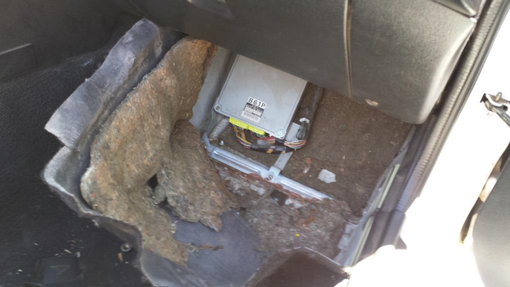
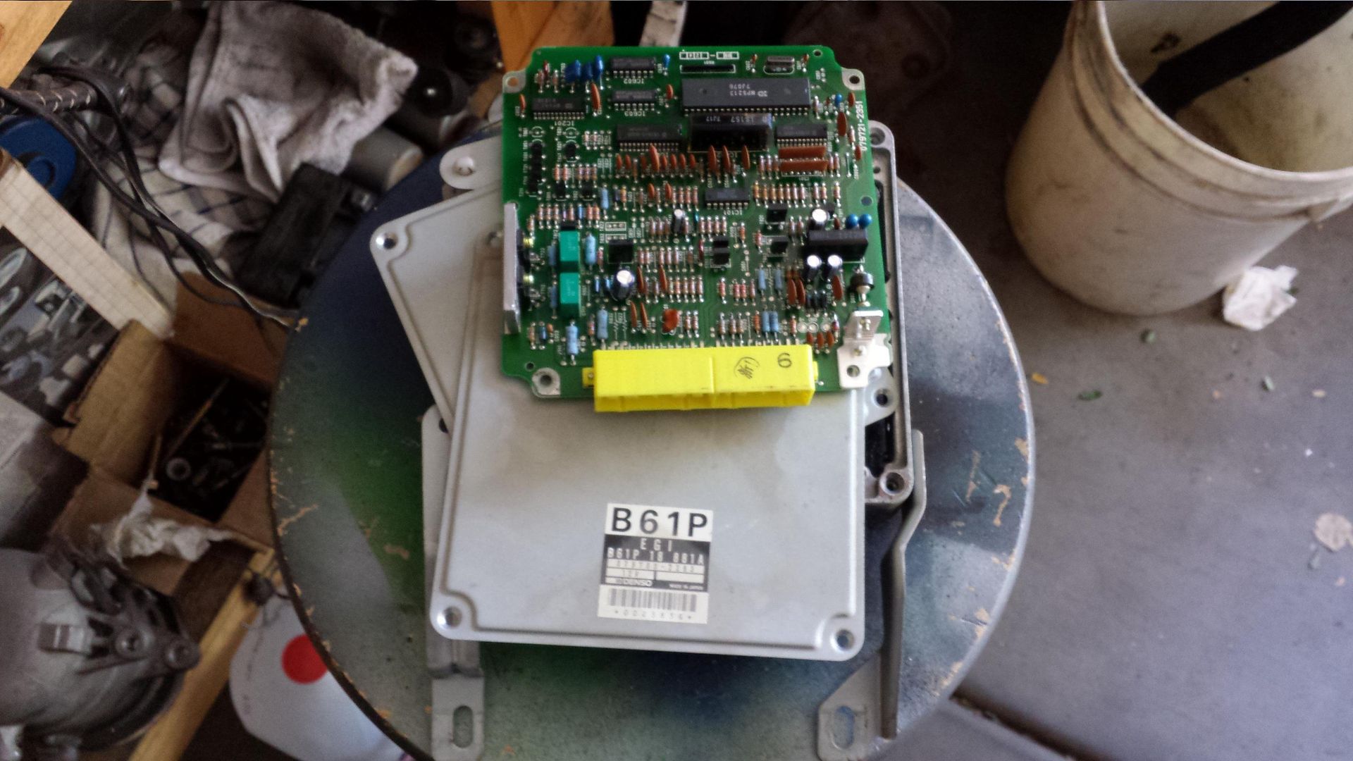
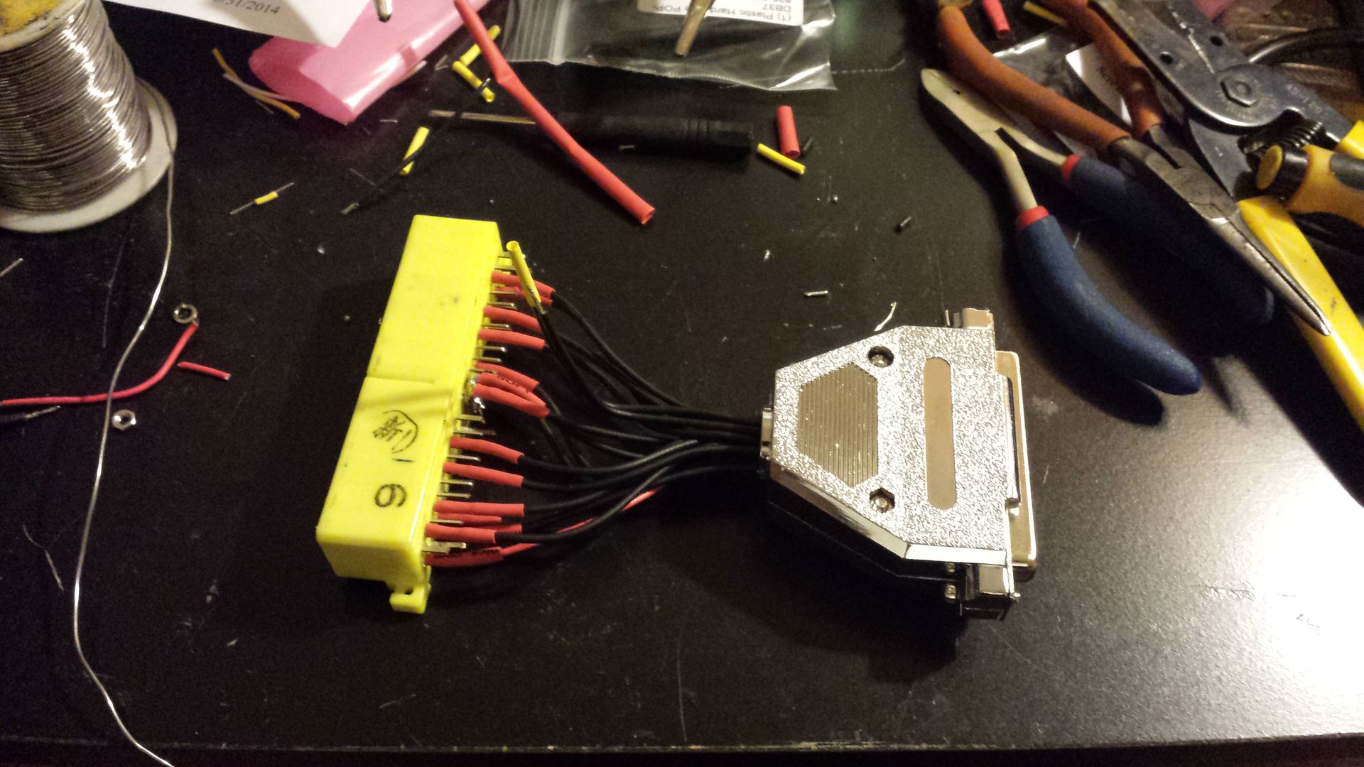
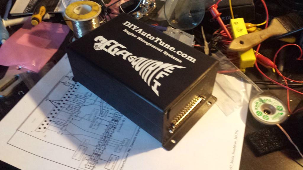
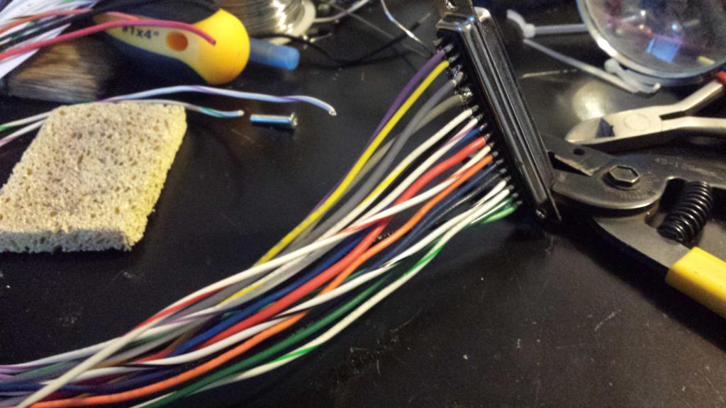
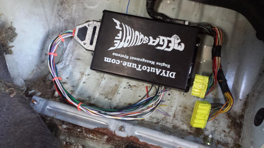
tore the connector out of the ecu made a boomslang, no going back now. i was to anxious to wait for a connector from mouser.
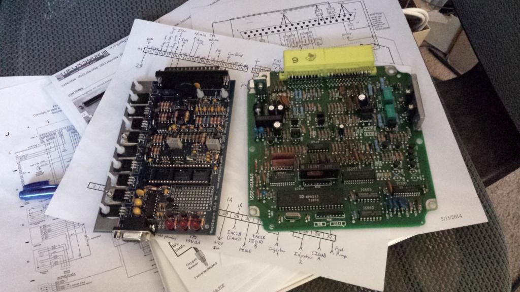
plans n ****
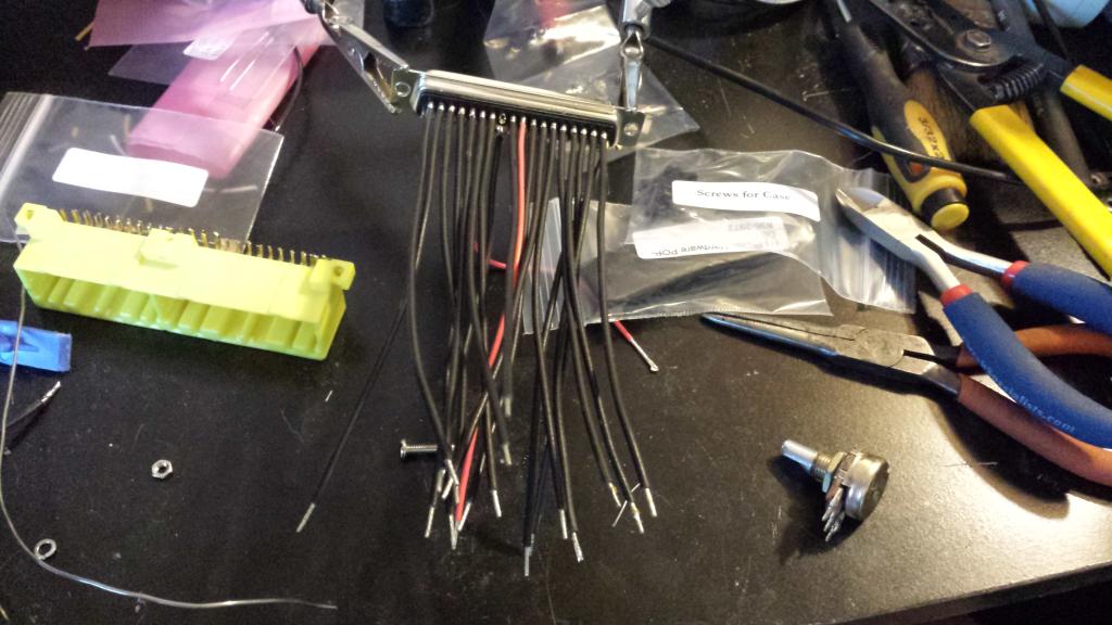
i wish i made it a little longer but i got this huge bag of pre-cut, stripped and tinned wires years ago that are great for **** like this and i got lazy.
and for the fans i will use D15. will a 2n2222 circuit run the fan relay? that transistor will supposedly pass 800mA, but i cant find a current draw spec on the fan relay. im about ready to go out there with a meter and measure it.
tore the connector out of the ecu made a boomslang, no going back now. i was to anxious to wait for a connector from mouser.
plans n ****
i wish i made it a little longer but i got this huge bag of pre-cut, stripped and tinned wires years ago that are great for **** like this and i got lazy.
Last edited by hi_im_sean; Jun 2, 2014 at 01:17 PM.
Reply
 0
0

0

Thread Starter
Joined: Sep 2012
Posts: 4,560
Total Cats: 1,143
From: your mom's house phoenix, AZ
i can grab a connector with my next mouser order and solder it in in 3.5 minutes, then i can call it rebuilt
Reply
0
0

No sarcasm, some people try to sell the stock ECUs for $50 in our classifieds.
The solder in connectors are $12 I think. That's what the ECU is worth so you can yank them out.
The solder in connectors are $12 I think. That's what the ECU is worth so you can yank them out.
Reply
0
0
Thread Starter
Joined: Sep 2012
Posts: 4,560
Total Cats: 1,143
From: your mom's house phoenix, AZ
They're $11 something at both Moser and Amazon last I checked. Leafy, from what I know many imports came with that connector including some fairly current models.
Reply
0
0
I just wish someone made a crimp style connector for this. The solder on connector that we all use has no strain relief because its designed to be mounted directly to a board. My boomslang harness I got from trackspeed for the ems4 has already had a pin fail in fatigue, luckily the pins are long and I was just able to jam it back into the connector and it still works.
Reply
0
0
Thread Starter
Joined: Sep 2012
Posts: 4,560
Total Cats: 1,143
From: your mom's house phoenix, AZ
I just wish someone made a crimp style connector for this. The solder on connector that we all use has no strain relief because its designed to be mounted directly to a board. My boomslang harness I got from trackspeed for the ems4 has already had a pin fail in fatigue, luckily the pins are long and I was just able to jam it back into the connector and it still works.
what if you back filled all the pins with silicone?
so anyone know what the fan relay draws and if a 2n2222 circuit will work? thats basically the last thing i need to do before i can slap it together and install it.
Reply
0
0
Thread Starter
Joined: Sep 2012
Posts: 4,560
Total Cats: 1,143
From: your mom's house phoenix, AZ
Reply
0
0

Thread Starter
Joined: Sep 2012
Posts: 4,560
Total Cats: 1,143
From: your mom's house phoenix, AZ
thanks schuyler
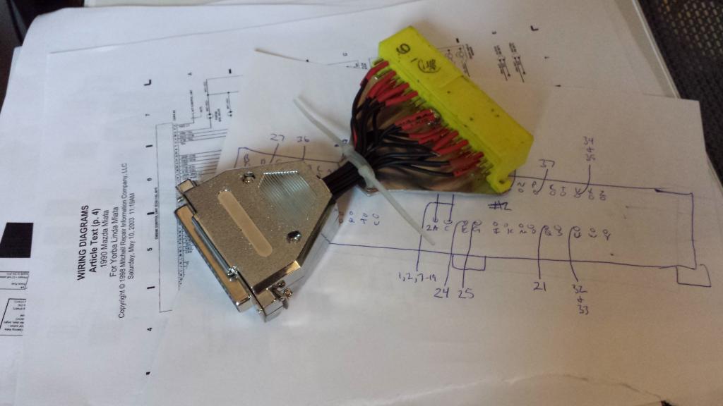
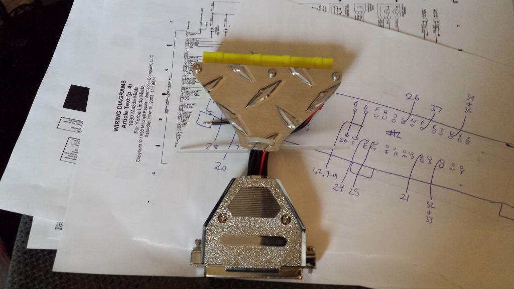
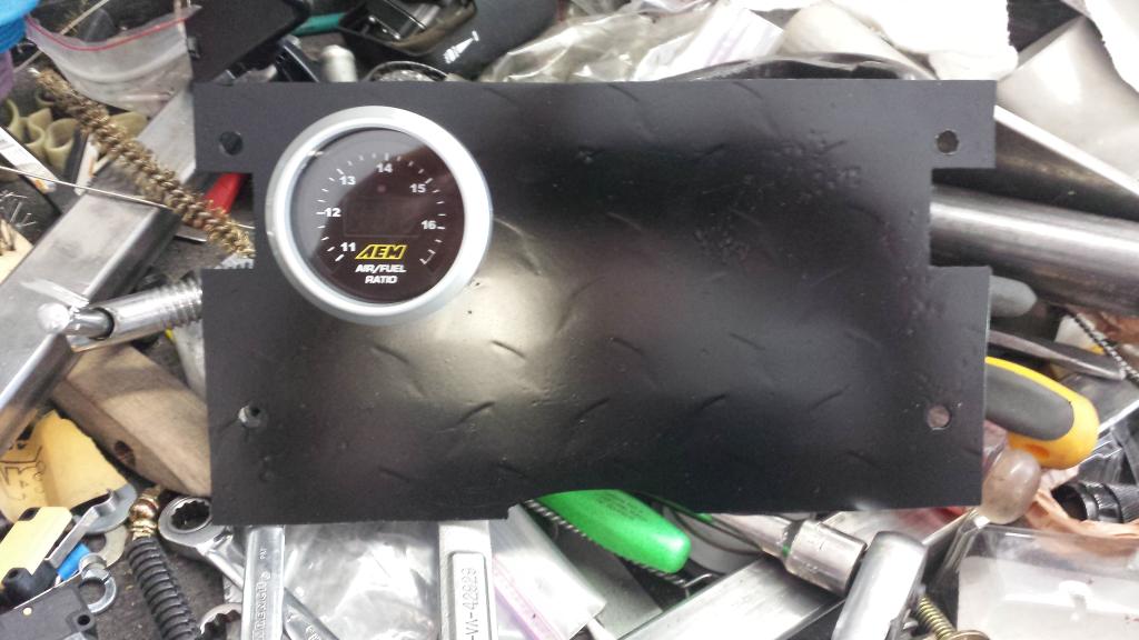
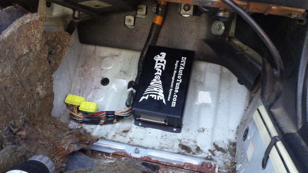
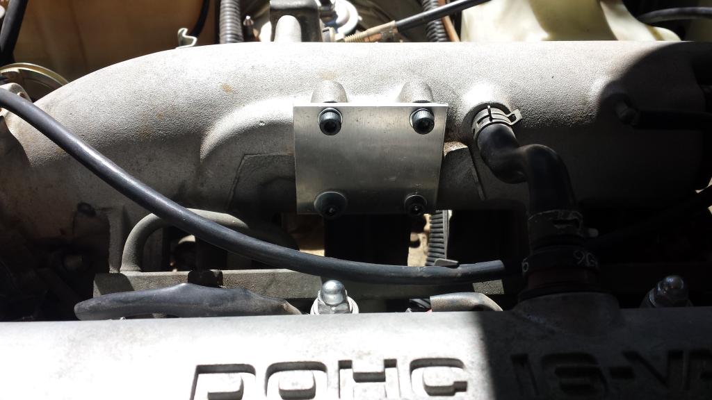
its not fancy but it works, the diamond plate should make the engine rev more freely. ill leave the zip ties loose until its in its final position.
its not fancy but it works, the diamond plate should make the engine rev more freely. ill leave the zip ties loose until its in its final position.
Reply
0
0

Reply
0
0
Thread Starter
Joined: Sep 2012
Posts: 4,560
Total Cats: 1,143
From: your mom's house phoenix, AZ

ironically, i have all the differnt color wire i needed and chose not to use it lol
Reply
0
0
Thread Starter
Joined: Sep 2012
Posts: 4,560
Total Cats: 1,143
From: your mom's house phoenix, AZ
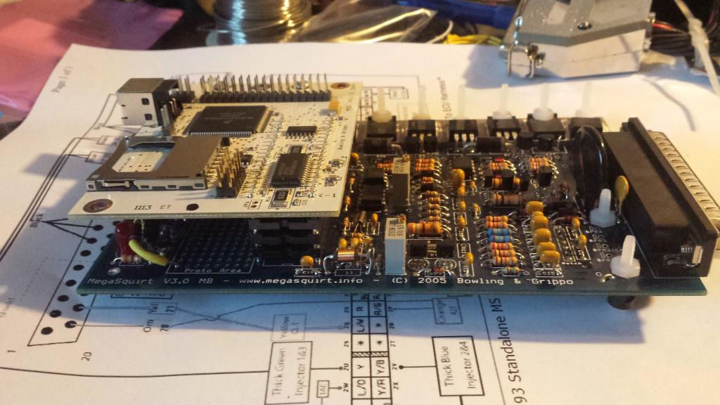
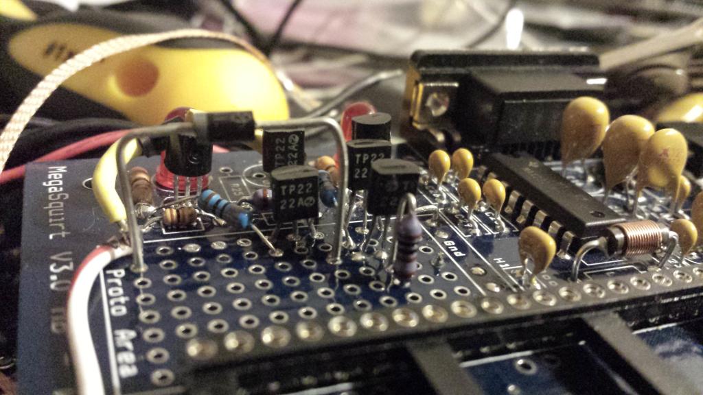
so i got all my 2n2222 circuits made. i powered it up with a 12v wall wart and did some voltage checks. all seemed good. i plugged the daughter board in and slapped it all together.
i installed all the drivers and software on my computer and got stuck at portcheck. it kept hanging up when it would get to port 3, which is the port im using. i drove myself nuts for about 3 hours, i tried 3 different computers running 3 different OS, reloaded everything, different com setting etc, and just called it a night. i woke up this morning and thought that maybe my 0.42A wall wart wasnt enough. so i hooked up my 5A bench unit and it worked! so i loaded my firmware, and started fiddling with tunerstudio.
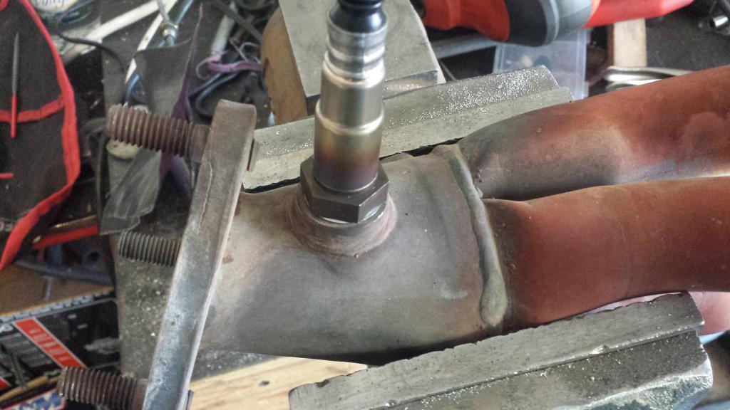
any issues running the wideband o2 in the stock bung? if i recall, dont they want to be at a slight downward angle? it doesnt appear to be when the manifold is installed, although i didnt really look.
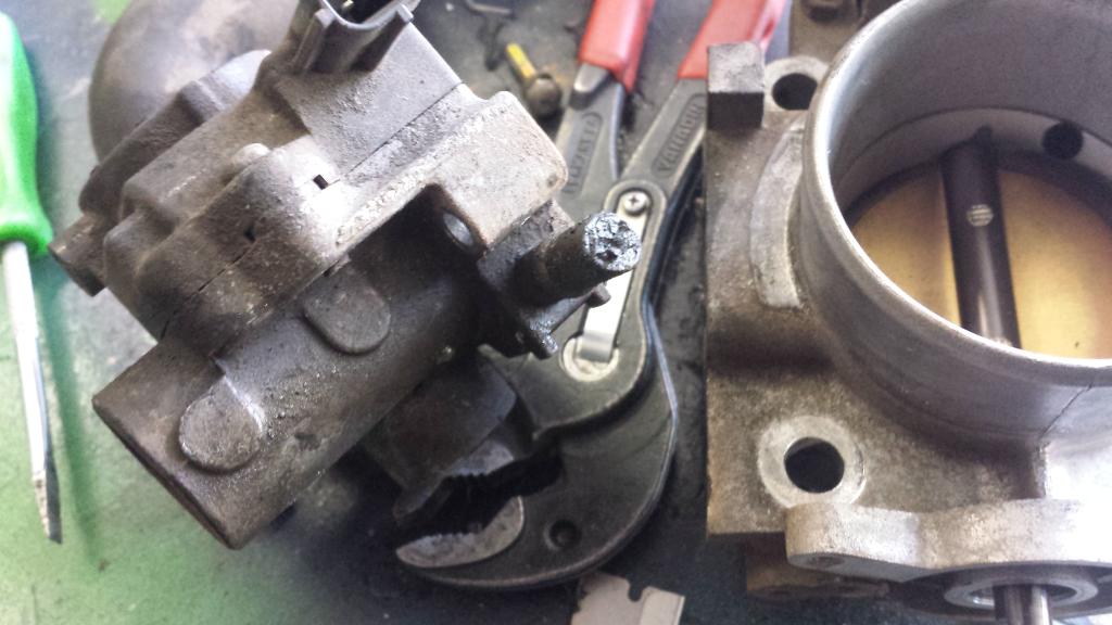
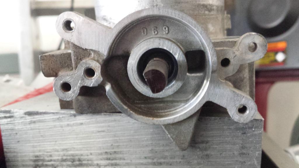
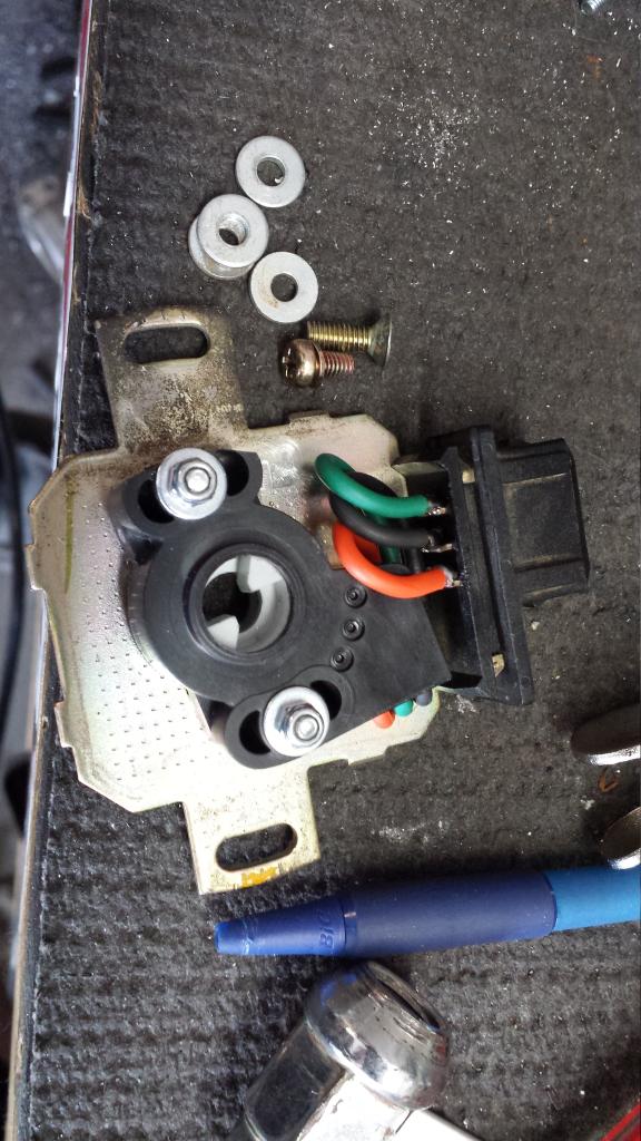
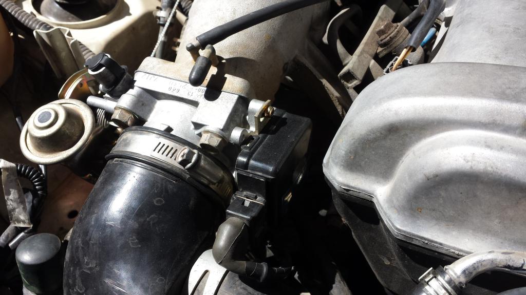
i yanked the throttle body to delete the IAC and figure out how i want to mount the TPS. i think i found why my IAC never really worked right.
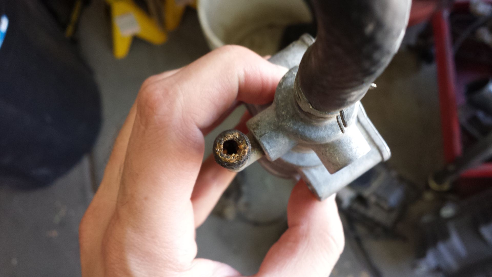
the water ports are solidified while at the same time falling apart.
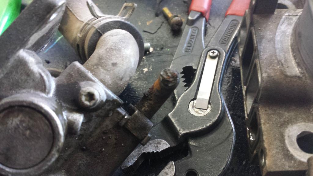
a piece if this elbow stayed in the hose
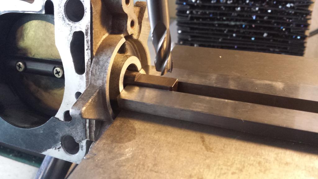
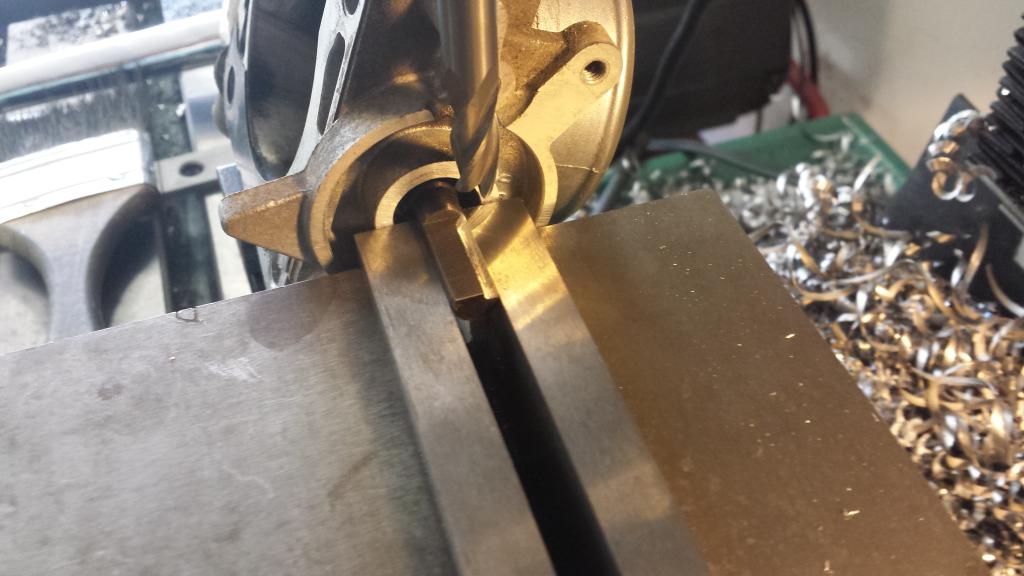
im going to make the wells tps fin inside the stock housing and use the factory connector and harness. this turned out to be more work than anticipated.
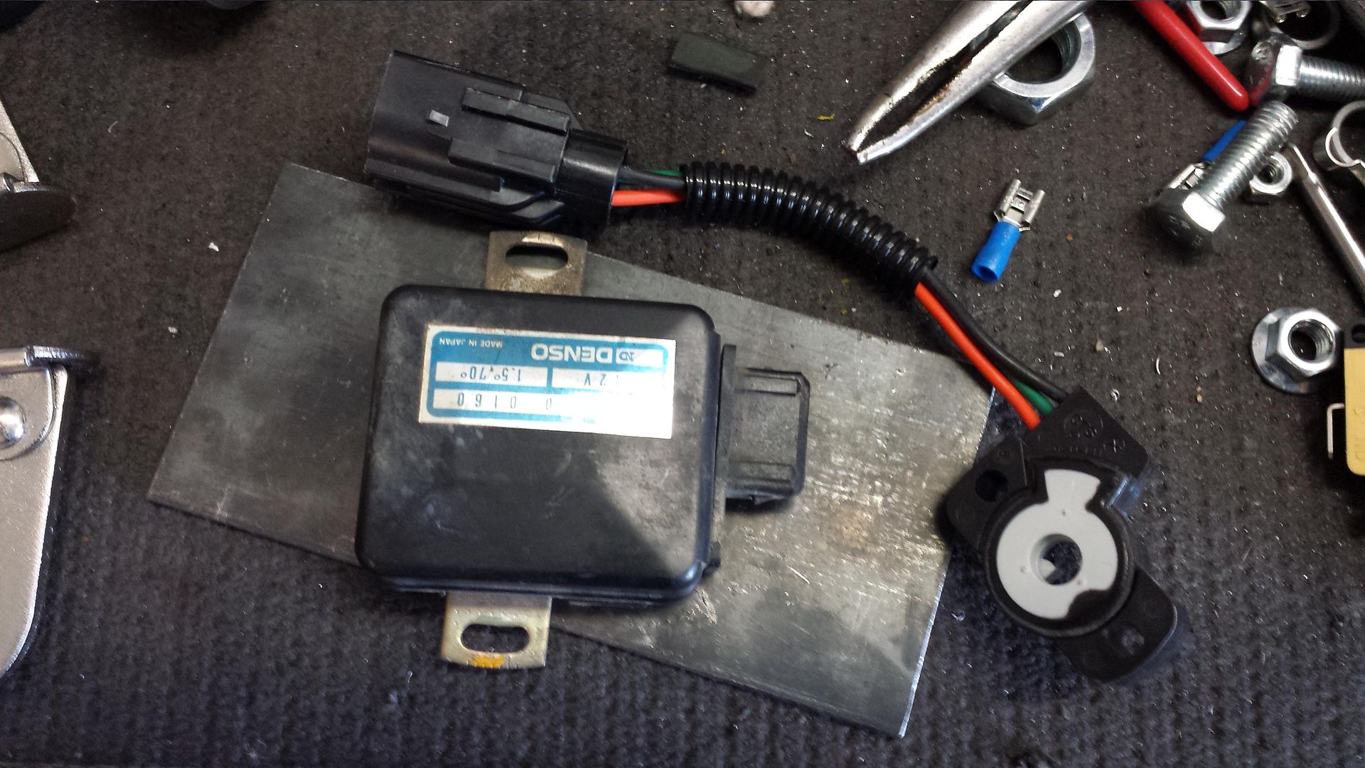
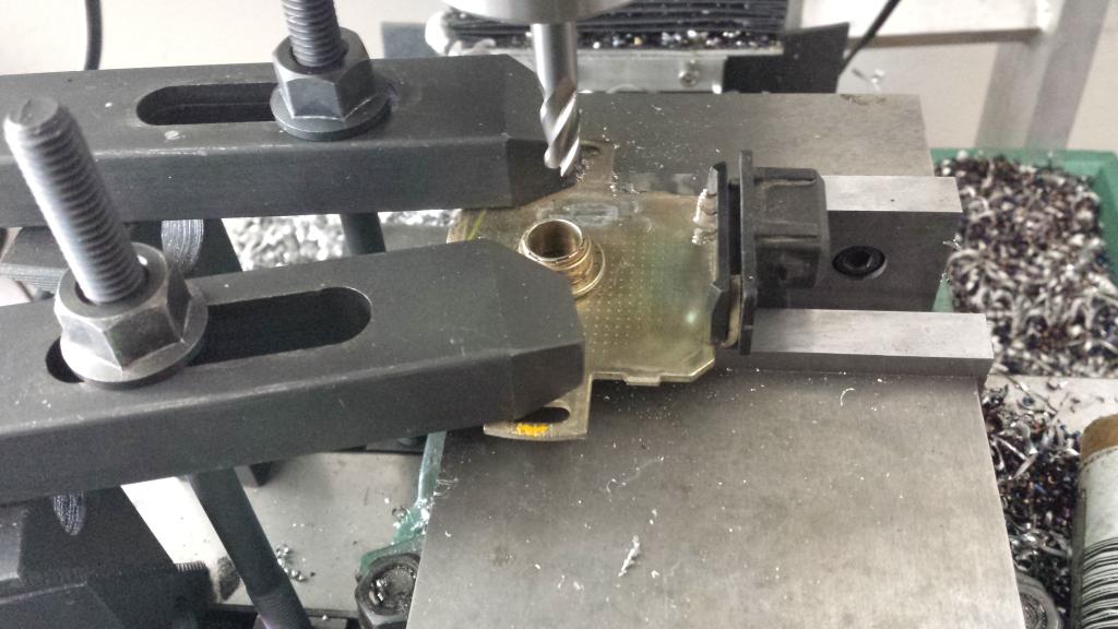
first i cut the leads short, broke the plastic cam doodad off, and milled all the crap off the surface
this bitch does not fit the wells TPS
i dont like the other solutions people have done, and i have a mill so why not
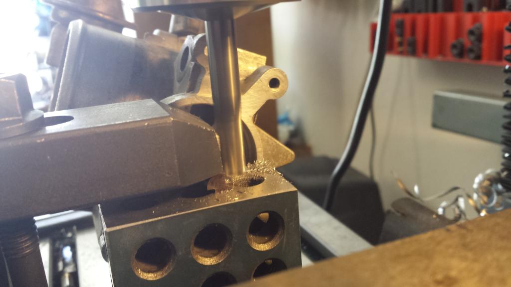
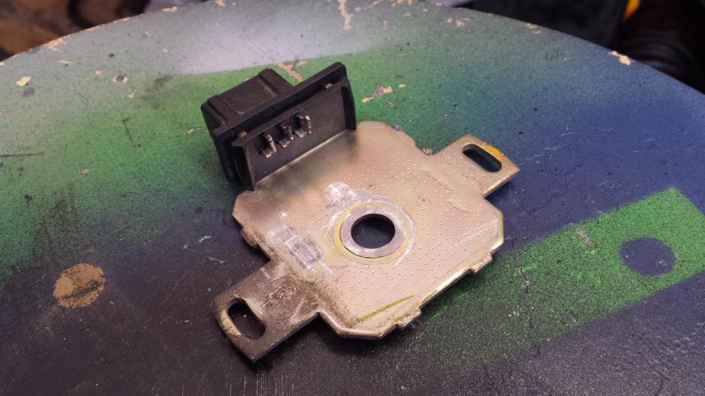
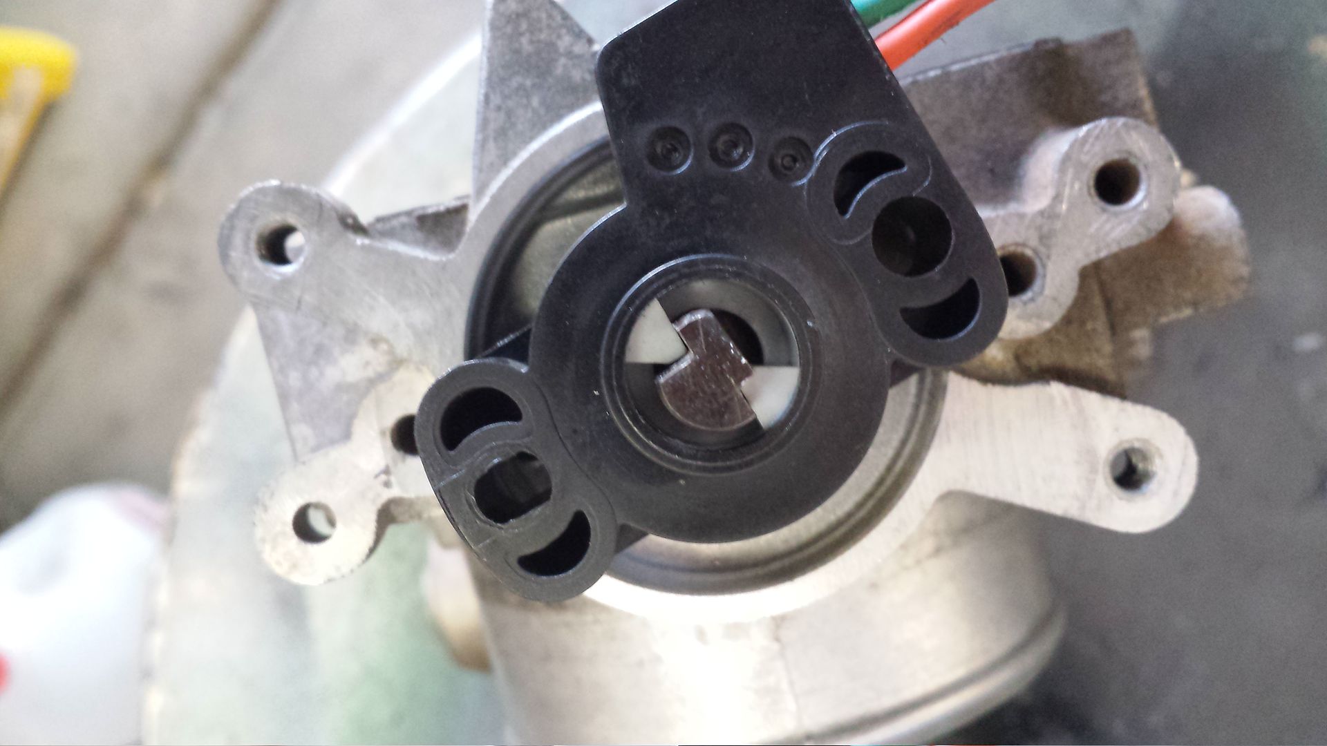
this finished result. im impressed for just eye ******* it (no measurements or setup) it fits like a glove
i got tired and its fuking hot outside, so thats it for now
edit- does tunerstudio full registraion not come with a new MS purchase? i assumed it did, and cant find any sort of reg card in my ****
i installed all the drivers and software on my computer and got stuck at portcheck. it kept hanging up when it would get to port 3, which is the port im using. i drove myself nuts for about 3 hours, i tried 3 different computers running 3 different OS, reloaded everything, different com setting etc, and just called it a night. i woke up this morning and thought that maybe my 0.42A wall wart wasnt enough. so i hooked up my 5A bench unit and it worked! so i loaded my firmware, and started fiddling with tunerstudio.
any issues running the wideband o2 in the stock bung? if i recall, dont they want to be at a slight downward angle? it doesnt appear to be when the manifold is installed, although i didnt really look.
i yanked the throttle body to delete the IAC and figure out how i want to mount the TPS. i think i found why my IAC never really worked right.
the water ports are solidified while at the same time falling apart.
a piece if this elbow stayed in the hose
im going to make the wells tps fin inside the stock housing and use the factory connector and harness. this turned out to be more work than anticipated.
first i cut the leads short, broke the plastic cam doodad off, and milled all the crap off the surface
this bitch does not fit the wells TPS
i dont like the other solutions people have done, and i have a mill so why not
this finished result. im impressed for just eye ******* it (no measurements or setup) it fits like a glove
i got tired and its fuking hot outside, so thats it for now
edit- does tunerstudio full registraion not come with a new MS purchase? i assumed it did, and cant find any sort of reg card in my ****
Reply
1
1
Thread Starter
Joined: Sep 2012
Posts: 4,560
Total Cats: 1,143
From: your mom's house phoenix, AZ
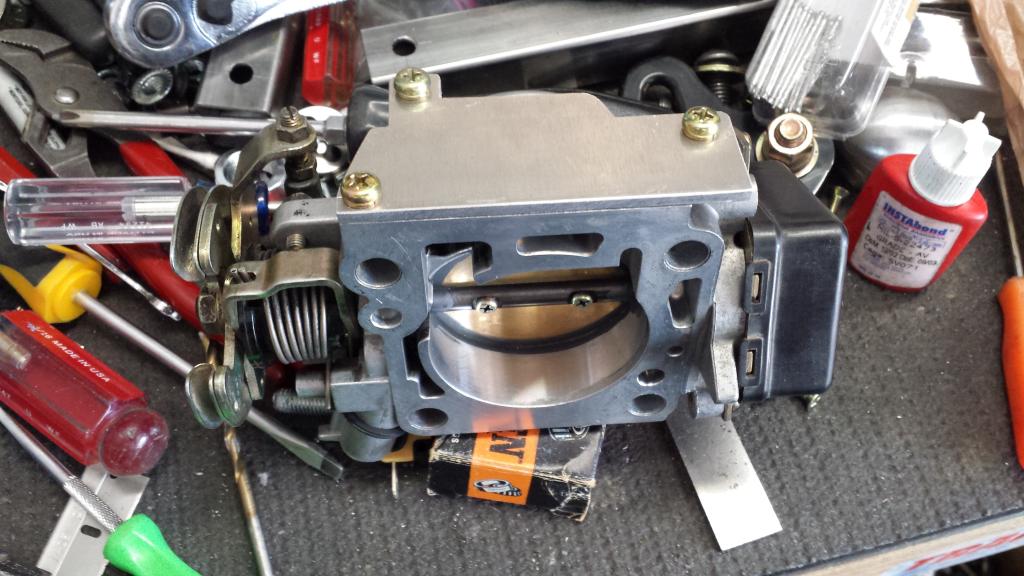
i gave the TB a bath and made a block off plate. you can see the assembled TPS attached
i removed the radio to make room for gauges and switches. i had some aluminum diamond plate laying around, which is to tacky for this car, so i used the smooth side; which was to reflective so i threw a shitty satin black on it.
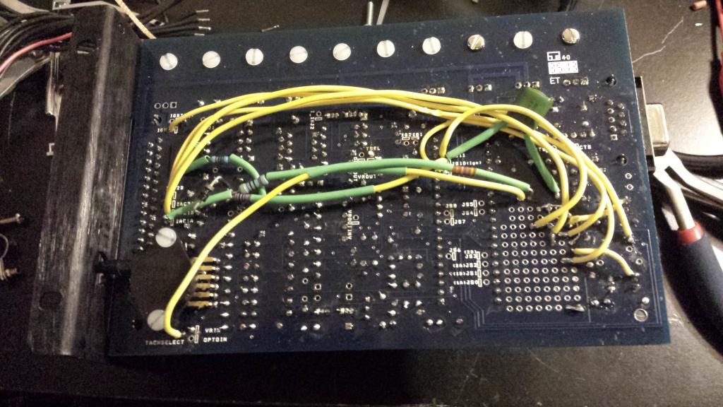
my boomslang angered me so i remade it. it was too short , no flexibility, it was **** work and i can do better.
i also decided to add some 2n2222 circuits because i have the spare outputs and wanted to redo the proto area and wiring anyhow. after more research, i realized i should have made a better EBC circuit as well using an an irfz44, so i did.
it did not work like this
more better
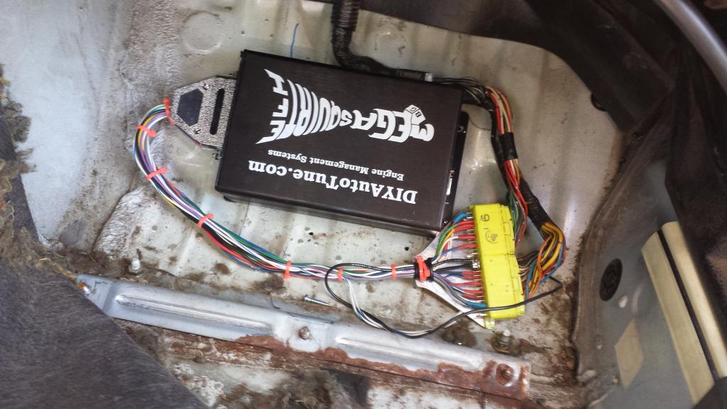
i beat the **** out of the ecu cover/foot holder with a hammer so it has a verified 1/4"+ gap above the MS
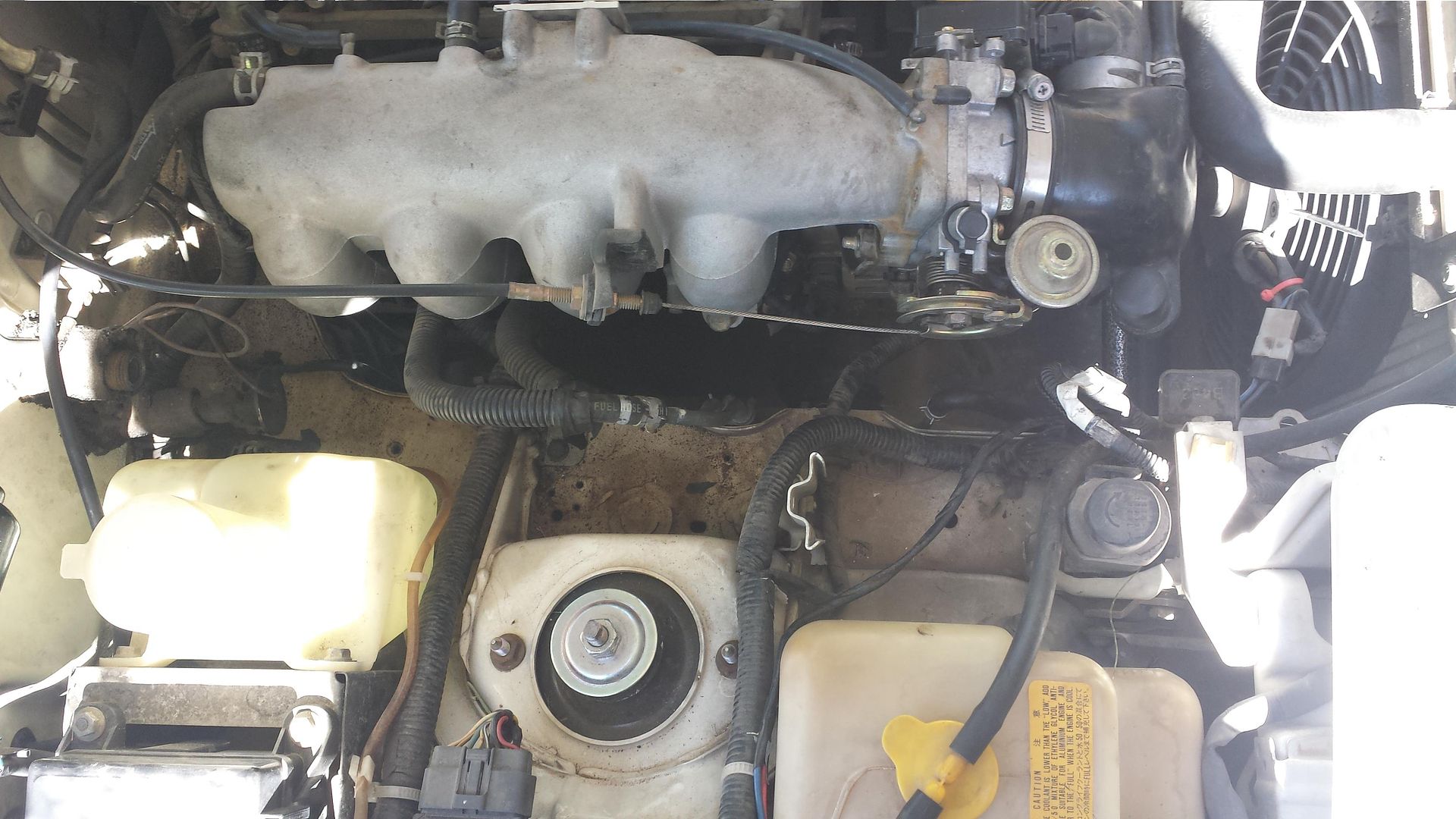
super awesome stealth TPS. the line right after the TB is the MAP line, would it be better to tee it off the FPR vacuum line?
i removed a few things
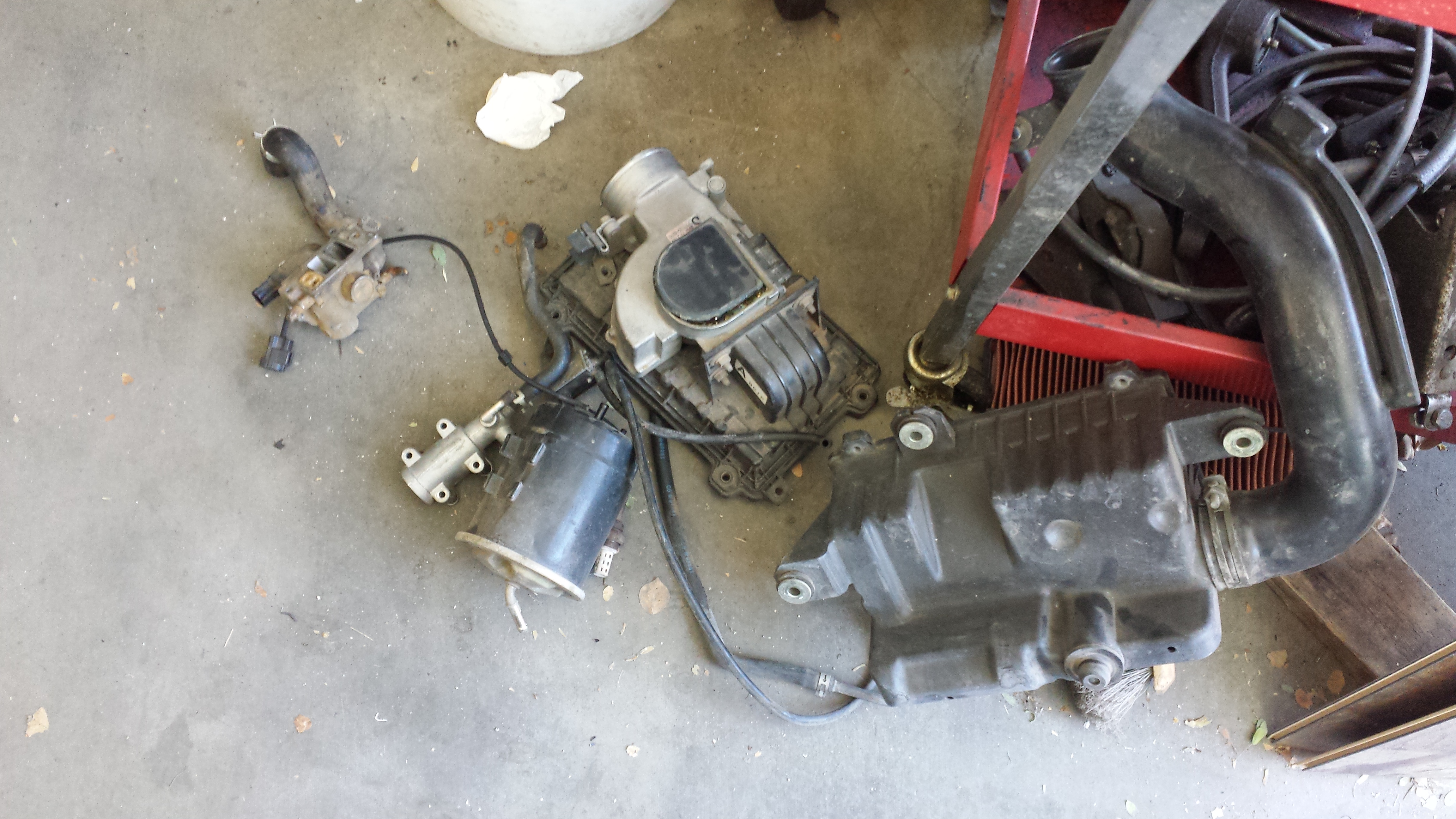
made a block off for the AV
it was also clogged solid as is the water inlet to the intake mani
i ran the map sensor line and the wideband harness. i just need to mount the gauge panel, wire up the wideband, and it should be ready to start
i should have enough wire left to put together a kit of say 10-12" lengths for you if interested
Reply
0
0


ugh, building all those circuits and running all those wires, should have just got an expander board, so much less work to do, worth the price and easily upgradeable from there.
if you had gone with the expander, all you need is 1 jumper wire on the bottom of the board to get it to work and you'd have EBC right now.
it also appears you were following old docs (or your own) why didnt you use the resources available to you at our expense?
the TB port is the worst place to source the map for the MS, tee off the FPR.
Reply
0
0


