When you click on links to various merchants on this site and make a purchase, this can result in this site earning a commission. Affiliate programs and affiliations include, but are not limited to, the eBay Partner Network.
nah, that engine needs rods and rings at a minimum before it goes back in to anything. I had blow by that caused oil to come past just about every seal, it drove me nuts. Plus, I have way too much invested in the 1.8 at this point to even think of going back temporarily.
I do wish I had left it in there for the last 9 or so months though. Ehh, water under the bridge.
I did just pick up another OA2076 that will serve nicely for parts to keep the other one alive, should I ever get it back on the road again. I am pretty sure that all-of-it on that setup would have resulted in ~250lbft at 3000 RPM.
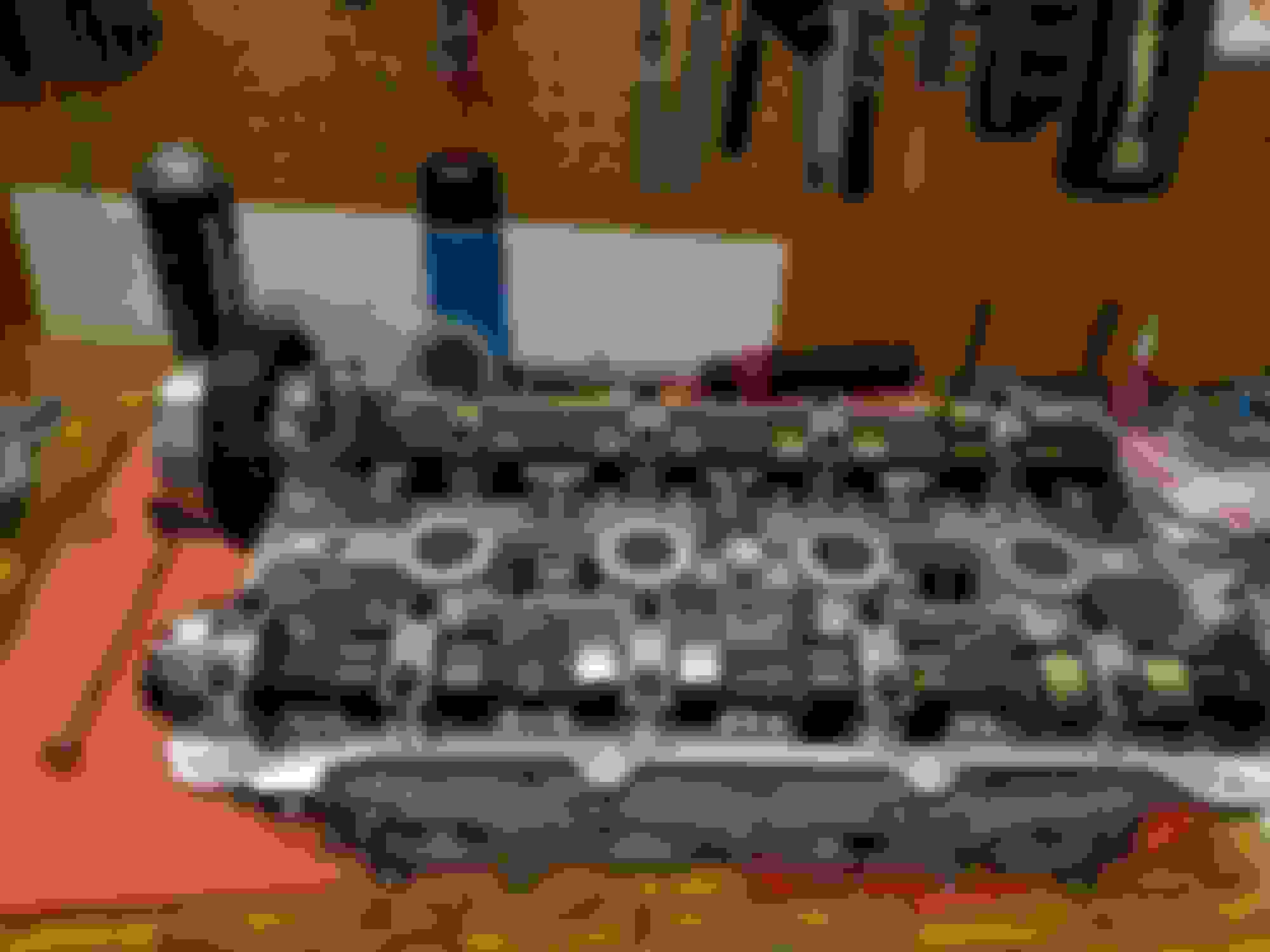
I finished the bulk of the head today. This represents a major milestone for me, as I can now start final assembly of the engine. I still have a bunch of misc. stuff to fab/build on the motor, a ton of electrical and a significant refactor of the charge cooling, but I am finding that I need to plan my activities more carefully so I don't run out of parts or materials needed for a specific task. The project feels much less open ended and daunting than it has for the last 9 months.
I think I literally have 100 hours into this head. I doubt that I will ever do this much work on a head again. I estimate that it would be ~$800-$1000 to get my machinist to do it. Stupid thing is that this is the second time I have done this :S
details on the head:
NB2 VVt with 1mm OS I/ex, inconel ex. ST SUBs, doubles with Ti retainers. Chamber polish, valve deshroud, minor bowl work. Miataroadster VVT rebuild kit and Mazda seals except the Valve seals.
Parts:
valves - ST MAEVI/MAIVN-1206
springs - ST SPRK-MM18S with SPR-3122
ST SUBs
Victor Reinz B45549 valve seals
Lot of detail work done, hoses, brackets and such. The oil drain became more of a project than I anticipated, but I M happy with the results.
Parts:
eBay aluminum -12AN weld bungs (2x)
eBay -10AN drain fitting with nipple cut off and drilled out to 0.7"
aluminum tube, ~0.7" id
earls AT806112ERL hose end
earls AT803112ERL hose end
earls PRO-LITE 350 -12AN hose
And now I bring you what I am sure is everybody's favorite topic, hoses and heat shields! If there was any question about my sanity, it should be cleared up now.
Is that an air intake tube to cool the exhaust manifold?
it is there actually to cool the shields I may or may not need it. If the aluminum is getting over say 850-900F, I will use it. There are actually flow channels inside the shields to encourage the air to go where I want.
it is there actually to cool the shields I may or may not need it. If the aluminum is getting over say 850-900F, I will use it. There are actually flow channels inside the shields to encourage the air to go where I want.
So I will be transitioning away from driveline hardware and into MS, electical, and control system land moving forward for the most part, but figured I would share a little story that nicely sums up why I abandoned setting calendar goals for my project. Only forward progress is the goal.
on a day where I had a couple of hours and hoped to knock 2 or 3 detail-ish tasks off the list....
I bring you the crank position sensor and mounting bracket.
nothing particularly interesting about this little guy. There are some interesting design features, such as the positioning boss and the interlock feature on the oil pump housing, made of steel, certain dimensions obviously intended to provide rigidity, and the ability to swap the sensor without removing the bracket.
and the problem:
The relocated alternator now causes the sensor and belt to occupy the same space.
solution: a new bracket that moves the sensor.
well, here is the oil pump mount on the mock-up
and here it is on the builder, which has a BE street-strip
the alignment feature is gone, and the mounting screw thread has been changed from a M4 to a M6.
the result
so a task that I had hoped would take less than an hour ended up consuming an entire work session.
Until next time, where I hope to present content on the thrilling topic of WG characterization and control.
Now I will begin more of the control system and electrical work for my project. I will begin by describing some of the activities relating to designing and implementing the boost control system. Anybody who has tried to tune the EBC on the Megasquirt knows that it sucks. Sorry, but it is true, be honest. Most people can fiddle with a slider, add some P, then add some I, then add some P, then a little D for good measure. They eventually get something that appears to work under the right conditions, but it doesn�t work �well� anywhere. The final system ends up being something like a pId (little p, BIG I, little d). This thing really should really be a Pi (BIG P, little i). We end up with little p BIG I because there are numerous non-linearities, and untracked dependencies. To name a few:
- Solenoid Voltage Dependence
- Solenoid dead time (turn-on, turn off)
- Solenoid Temperature
- Sensitivity variability due to valve differential pressure across solenoid
- Sensitivity variability due to valve differential pressure across flow valve
- Hysteresis in valve
- Sticky valve
In a single variable process controller, one can fudge in some coefficients that make up for a non-linear plant and get away with it. With a process that has two interacting variables, it simply doesn�t work. I implemented a boost control scheme based on the following diagram in the Gen1 prototype.
It actually worked surprisingly well, but doesn�t offer anywhere near the level of control I will be targeting for the second generation design. Specifically, I will be utilizing boost-by-gear, a valet/wife mode, potentially e85 based boost, and the other goodies that the MS3 offers and the MS2 didn�t. Conceptually, the �boost� (a terrible term, hate using it) from each stage as well as the composite is shown in the following figure.
Normally, I would simply build an external controller, but the Megasquirt has access to (most of) the control parameters, it does have a PID with feed-forward and a target look-up table in place. The objective will be to linearize the plant externally, as well as mixing the various compressor contributions. This will allow the Megasquirt to in essence control a linear process, which is what it really wants to do. There will be a couple of dependencies I will try to get away with not accounting for. Specifically, I will not be monitoring the solenoid temperatures. I will also most likely not be monitoring the differential pressures across the wastegates. The wastegate differential pressure does impact the system response with a square-root term, so hopefully I can get the I term to manage that.
The proposed Gen2 block diagram is shown below
The first installment will focus on the Solenoid itself. The following figure is a scope shot of the voltage and current waveforms of one of DIYautotune�s solenoids with an external driver. PWM is supplied via Arduino.


 0
0