
Twin charged mischief –a risky parochial build, predicated on twisted logic


Thread Starter
Junior Member
Joined: May 2007
Posts: 340
Total Cats: 98
From: Toronto Area, Ontario
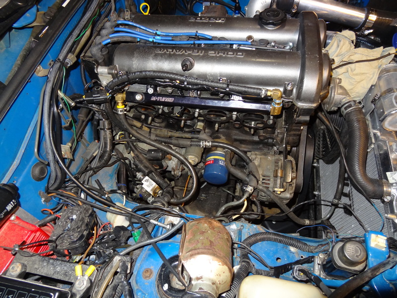
In order to get the supercharger to sit as close as possible to the engine, the front left mounting bolt would have to co-exist with my fuel system.
So, I re-routed the fuel lines, and fuel injector wires, to run on top of the fuel rail.
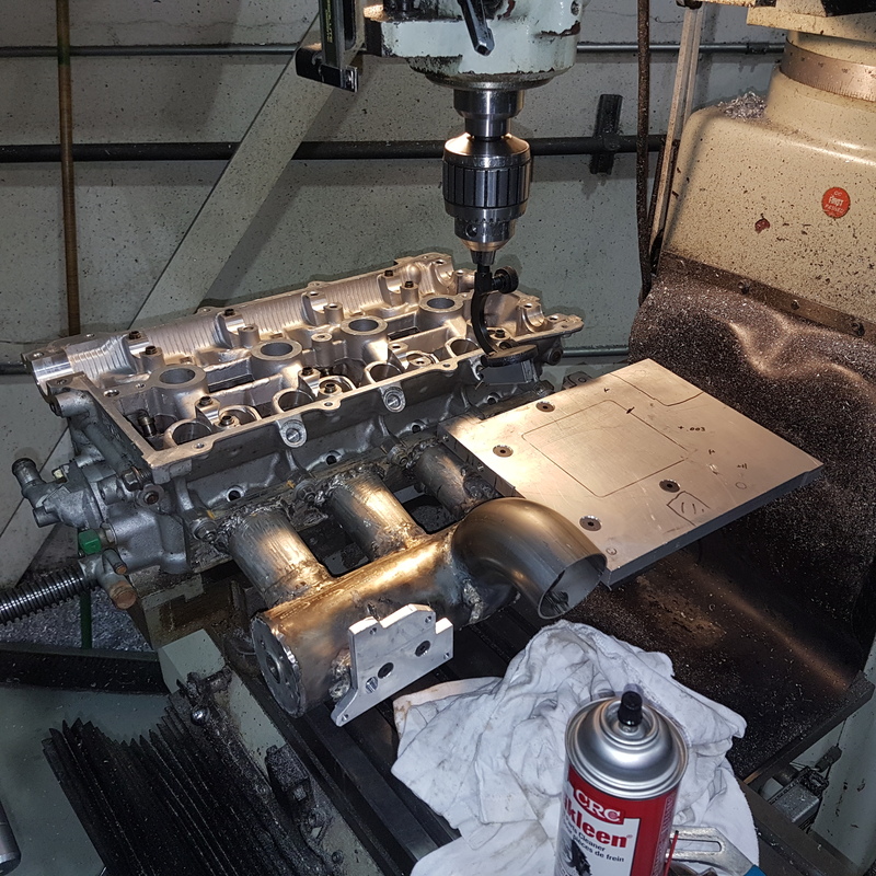
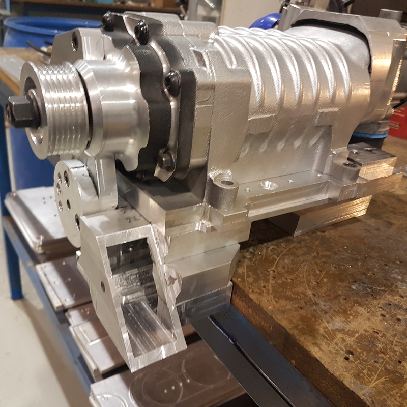
After welding the supports on the manifold, I cut the main supercharger plate, and then levelled it using a dial gauge on the mill.
I had problems in my last set up, getting the belt aligned, which I don’t want to repeat.
Initially, I was going to mount the supercharger on a 1” plate, but after I found I had clearance, and that I had very little for the outlet, I decided to add an additional ˝” to it.
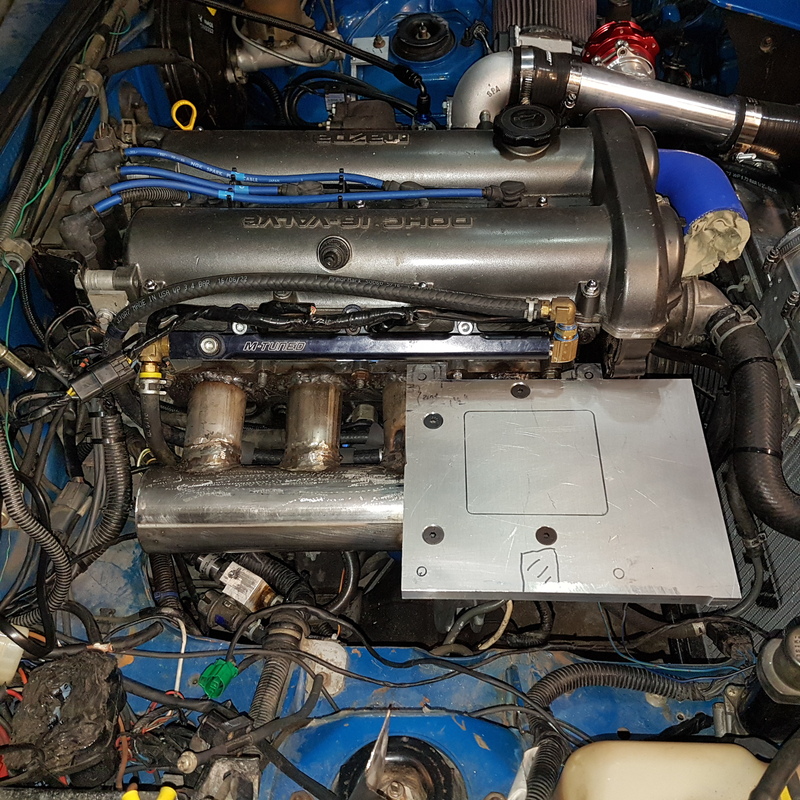
I went a little overboard, with the amount of fasteners holding the upper to lower plate.
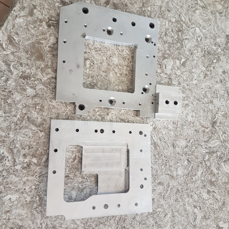
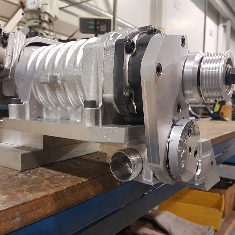
Since I don’t have an aluminum welder, and the pipe to connect the supercharger mounting plate to the outlet pipe would need to start off “L” shaped,
and avoid various pieces (manifold, alternater etc) I ended up getting 1” thick aluminum plates, and cutting them into the correct shape.
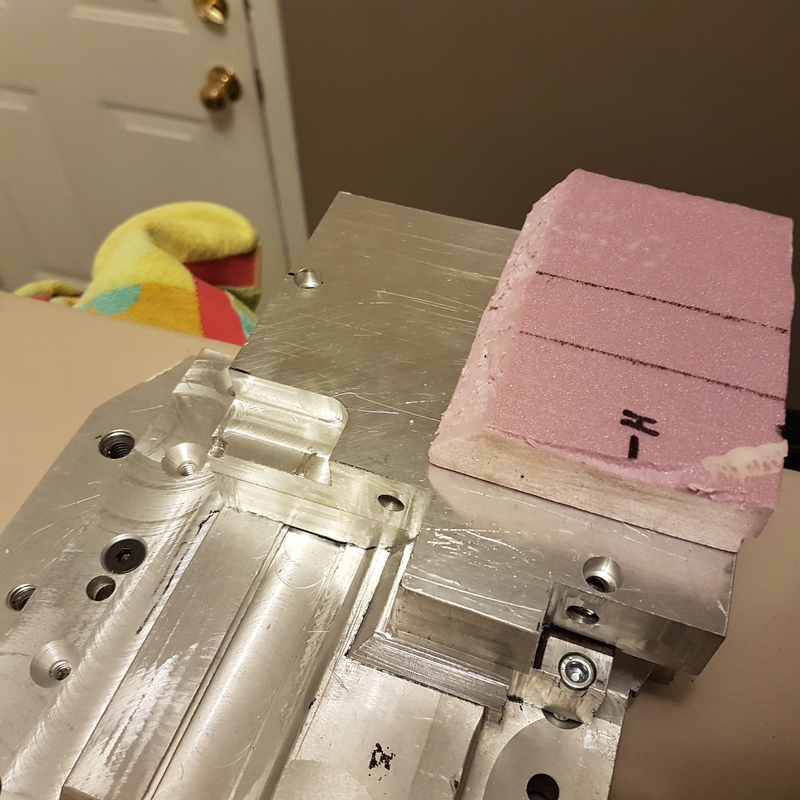
I used styrofoam, to get close to the correct shape and then duplicate it.
The plates are bolted one after another to each other.It worked out ok, but was a lot of work.
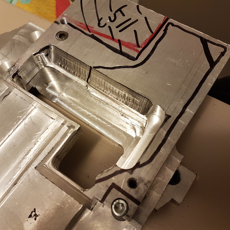
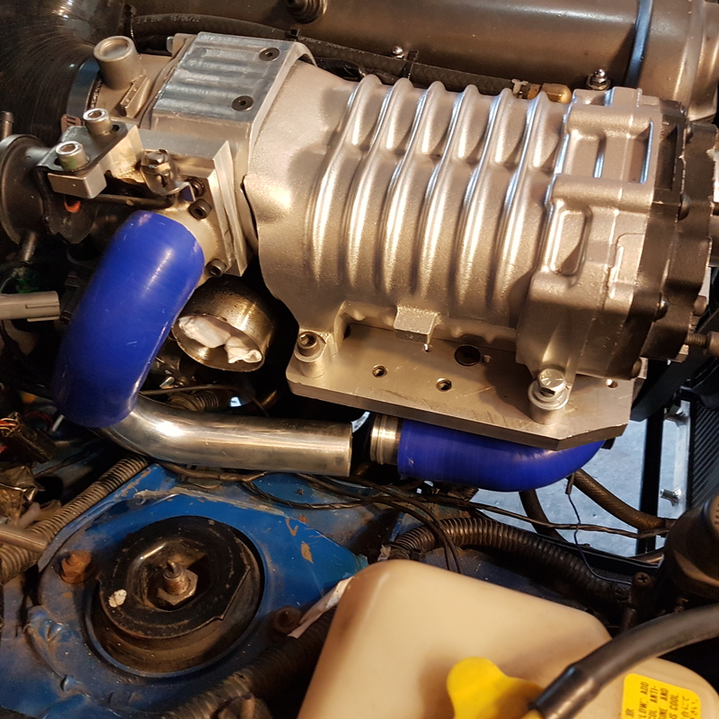
Not much space below the supercharger, to route the charge pipes.
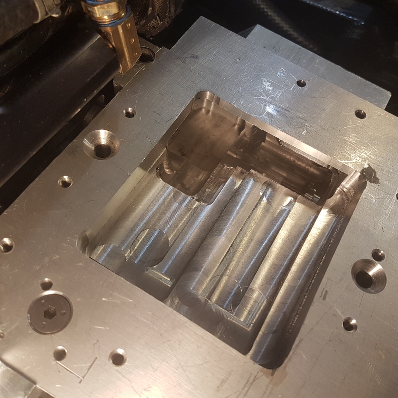
The outlet port is a weird shape, but I only have 1.6" between the supercharger belt, and front cover of the engine, so needed to get creative.
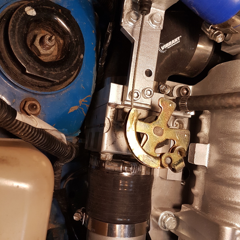
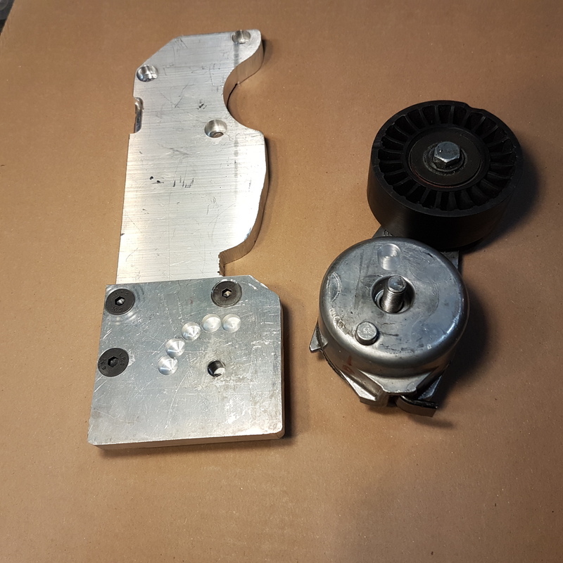
This location for the tensioner, was found to not work. I couldn't get a ratchet on the tensioner to install the belt.
Throttle body
Unfortunately, there was not enough space to mount the previously installed 70mm Honda throttle body.
I had to go with the stock unit, and had to machine the body down considerably.
Made a bracket, base plate and mounted it to the supercharger plate.
There was enough room to bring the 2.5” od piping right back to the intercooler.
Throttle body is pretty close to the engine bay walls, but I should have enough clearance there.
Bypass hoses nearly sorted out.
Exhaust system
With my previous supercharger system, I was running a custom header, and a 2.5” exhaust.
The exhaust consisted of a 200cell carsound cat, a magnaflow 4x22” round resonator and then a 5x11x22” magnaflow main muffler.
These were the largest well flowing components I could find, and were needed to get the car to be reasonable sounding.
When I put the turbo on,I installed a 3” down pipe, and 3” into the cat.The exhaust was incredibly quiet.Like a Buick.In fact, there was no exhaust note at all.
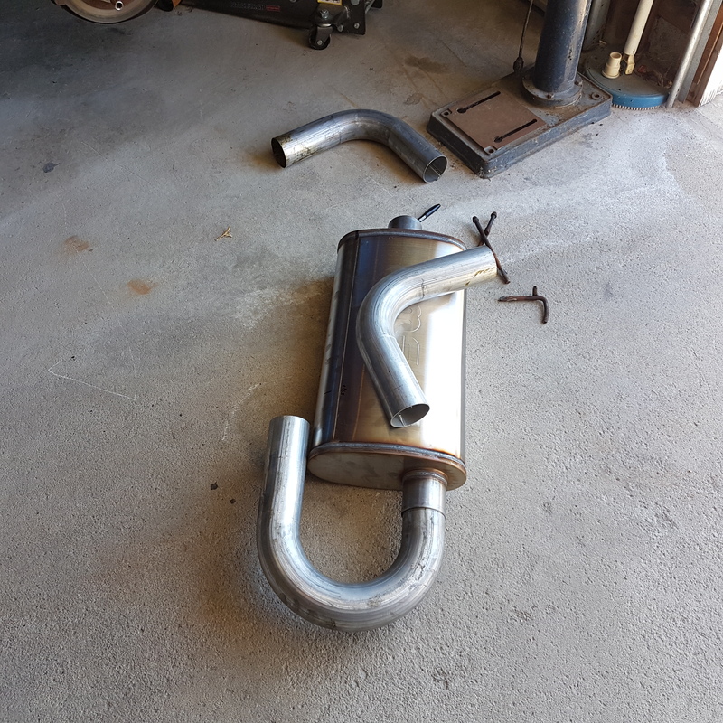
Since the 2.5” exhaust is hurting spool and flow, I decided topick up the same size magnaflow muffler in 3” and some mandrel bent tubing to connect things.
I had a left over 4x18” round resonator in 3” that I had installed at one point which I also installed.
So now I am running 3” front to back.I forgot how much I hate doing exhaust work.
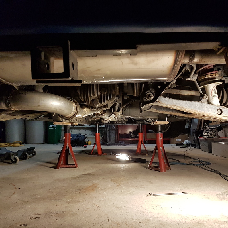
Tensioner bracket etc is now complete but sI till have quite a number of things to do. The 2 air cleaners is a temporary setup.
Currently I am implementing a single air cleaner solution.
Tensioner location
So, I re-routed the fuel lines, and fuel injector wires, to run on top of the fuel rail.

After welding the supports on the manifold, I cut the main supercharger plate, and then levelled it using a dial gauge on the mill.
I had problems in my last set up, getting the belt aligned, which I don’t want to repeat.
Initially, I was going to mount the supercharger on a 1” plate, but after I found I had clearance, and that I had very little for the outlet, I decided to add an additional ˝” to it.


I went a little overboard, with the amount of fasteners holding the upper to lower plate.

Since I don’t have an aluminum welder, and the pipe to connect the supercharger mounting plate to the outlet pipe would need to start off “L” shaped,
and avoid various pieces (manifold, alternater etc) I ended up getting 1” thick aluminum plates, and cutting them into the correct shape.
I used styrofoam, to get close to the correct shape and then duplicate it.
The plates are bolted one after another to each other.It worked out ok, but was a lot of work.


Not much space below the supercharger, to route the charge pipes.

The outlet port is a weird shape, but I only have 1.6" between the supercharger belt, and front cover of the engine, so needed to get creative.

This location for the tensioner, was found to not work. I couldn't get a ratchet on the tensioner to install the belt.

Throttle body
Unfortunately, there was not enough space to mount the previously installed 70mm Honda throttle body.
I had to go with the stock unit, and had to machine the body down considerably.
Made a bracket, base plate and mounted it to the supercharger plate.
There was enough room to bring the 2.5” od piping right back to the intercooler.

Throttle body is pretty close to the engine bay walls, but I should have enough clearance there.

Bypass hoses nearly sorted out.

Exhaust system
With my previous supercharger system, I was running a custom header, and a 2.5” exhaust.
The exhaust consisted of a 200cell carsound cat, a magnaflow 4x22” round resonator and then a 5x11x22” magnaflow main muffler.
These were the largest well flowing components I could find, and were needed to get the car to be reasonable sounding.
When I put the turbo on,I installed a 3” down pipe, and 3” into the cat.The exhaust was incredibly quiet.Like a Buick.In fact, there was no exhaust note at all.
Since the 2.5” exhaust is hurting spool and flow, I decided topick up the same size magnaflow muffler in 3” and some mandrel bent tubing to connect things.
I had a left over 4x18” round resonator in 3” that I had installed at one point which I also installed.
So now I am running 3” front to back.I forgot how much I hate doing exhaust work.


Tensioner bracket etc is now complete but sI till have quite a number of things to do. The 2 air cleaners is a temporary setup.
Currently I am implementing a single air cleaner solution.

Tensioner location

Reply
 8
8

8


It's an awesome build, I've been following it closely. I can't wait to see it finished, and see datalogs/dyno plots/time slips/ and driving impressions. This thing is gonna be sweet.
Reply
0
0
Thread Starter
Junior Member
Joined: May 2007
Posts: 340
Total Cats: 98
From: Toronto Area, Ontario
thanks, hopefully it will be worth the trouble.
thanks Pat. I am very interested in seeing how this thing works, and yes I will be fully transparent, good or bad.
Need some humor. Link to Australian deck stain commercial. (I doubt it's real)
Reply
1
1
Thread Starter
Junior Member
Joined: May 2007
Posts: 340
Total Cats: 98
From: Toronto Area, Ontario
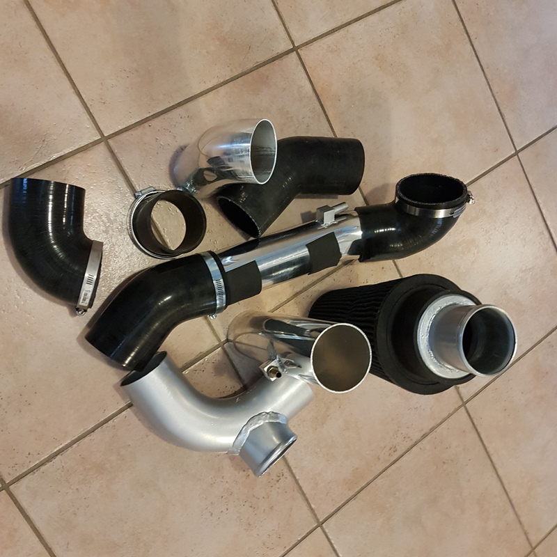
So I spent the last couple of days, finishing off the pipe from the supercharger to the turbo, as well as the piping for the single air cleaner.(ok,
and a bunch of little things)
The pipe leaving the supercharger is oval, since I have very little clearance between the front cover and the supercharger belt.
Even so, I ended up cutting half of the front cover off, to get more clearance.
This component is part of the supercharger mounting, so it needed an o-ring gasket to allow for easy installation of the outlet pipe.
I thought it would be difficult to machine this shape, but it was no problem really.
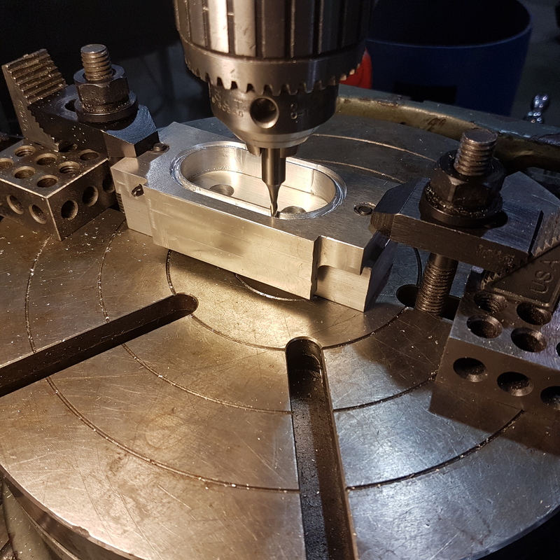
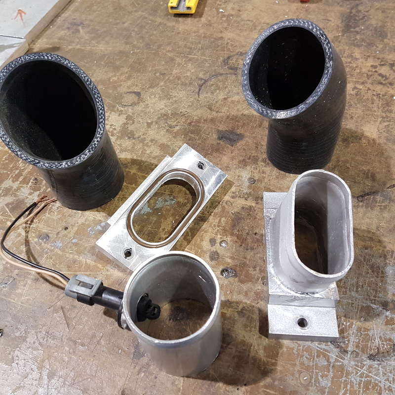
The part below with the brown o-ring, mounts to the supercharger mounting plate assembly.
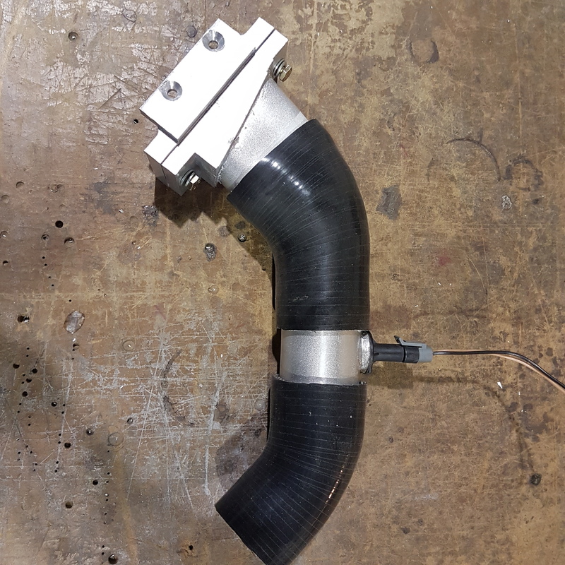
The other components connect the supercharger mounting plate, to the turbo inlet hose.
I am planning on measuring the temperature of the supercharger outlet, hence the sensor.
There may be an issue with intake noise.
When the turbo is fully spooling, the ETB2 opens which lets additional air in to the turbo inlet.
If you have ever had a silicone hose pop off on the pressurized side in a supercharged car, you know that the supercharger makes
a lot of noise when moving air. It can be loud and it's not a pleasing sound.
Not sure how bad this will be in this case, as all the air coming out of the supercharger is being gobbled up by the turbo. Maybe not that
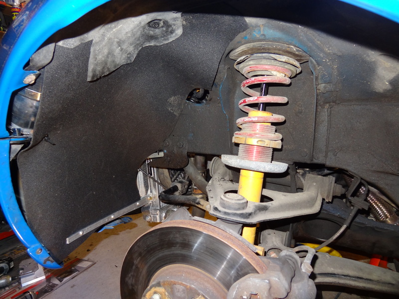
much sound will actually be coming out . Anyway, I decided to mount the air cleaner under the fender which will give me cool air
and move any noise further away from the cockpit.
Quite a collection of pipes and silicone couplers, not to mention lots and lots of hose clamps.
A look at under the fender.
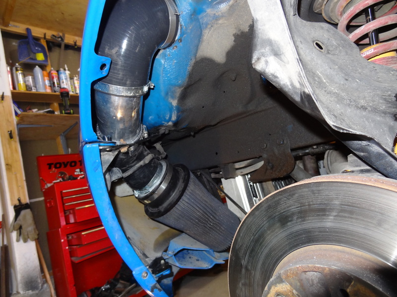
Not sure how long this cover up treatment will last.
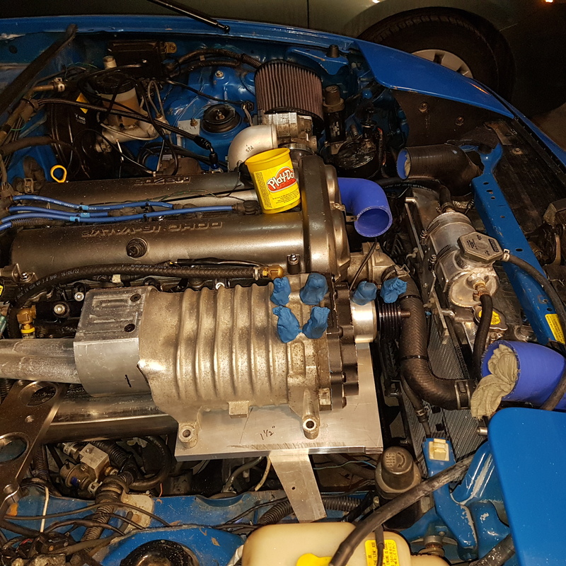
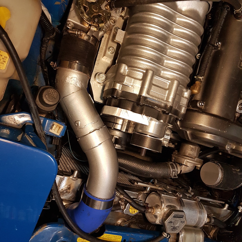
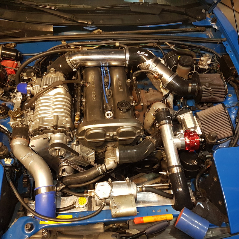
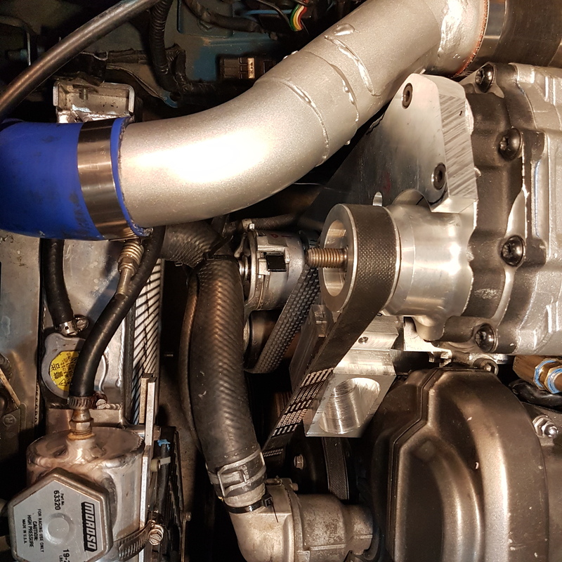
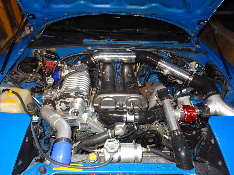
Current under hood shot. Honestly I am surprised at how easy this is to work on. There is room to access all the fasteners, and
I can remove individual components pretty easily. I am pretty happy with the way this is going from an install point of view.
I had a huge setback with the tensioner bracket.I lost it.
I was test fitting it with the tensioner, and after doing that, I removed the tensioner, but forgot to remove the bracket.
The bolts were on finger tight and the bracket violently fell off while I was testing boost control on the highway.
Spent a good amount of time looking for it, but it went off into the grass beside the highway so it’s gone.
I was hoping to go to an autocross tomorrow(turbo only), but the boost control is not working properly (I upgraded to a 4 way valve and now the boost is oscillating badly)
and I don’t feel confident in the car right now.Got some wiring, computer work and the tensioner bracket left to do. Getting closer....
and a bunch of little things)
The pipe leaving the supercharger is oval, since I have very little clearance between the front cover and the supercharger belt.
Even so, I ended up cutting half of the front cover off, to get more clearance.
This component is part of the supercharger mounting, so it needed an o-ring gasket to allow for easy installation of the outlet pipe.
I thought it would be difficult to machine this shape, but it was no problem really.

The part below with the brown o-ring, mounts to the supercharger mounting plate assembly.
The other components connect the supercharger mounting plate, to the turbo inlet hose.
I am planning on measuring the temperature of the supercharger outlet, hence the sensor.


There may be an issue with intake noise.
When the turbo is fully spooling, the ETB2 opens which lets additional air in to the turbo inlet.
If you have ever had a silicone hose pop off on the pressurized side in a supercharged car, you know that the supercharger makes
a lot of noise when moving air. It can be loud and it's not a pleasing sound.
Not sure how bad this will be in this case, as all the air coming out of the supercharger is being gobbled up by the turbo. Maybe not that
much sound will actually be coming out . Anyway, I decided to mount the air cleaner under the fender which will give me cool air
and move any noise further away from the cockpit.
Quite a collection of pipes and silicone couplers, not to mention lots and lots of hose clamps.

A look at under the fender.

Not sure how long this cover up treatment will last.

Current under hood shot. Honestly I am surprised at how easy this is to work on. There is room to access all the fasteners, and
I can remove individual components pretty easily. I am pretty happy with the way this is going from an install point of view.

I had a huge setback with the tensioner bracket.I lost it.
I was test fitting it with the tensioner, and after doing that, I removed the tensioner, but forgot to remove the bracket.
The bolts were on finger tight and the bracket violently fell off while I was testing boost control on the highway.
Spent a good amount of time looking for it, but it went off into the grass beside the highway so it’s gone.
I was hoping to go to an autocross tomorrow(turbo only), but the boost control is not working properly (I upgraded to a 4 way valve and now the boost is oscillating badly)
and I don’t feel confident in the car right now.Got some wiring, computer work and the tensioner bracket left to do. Getting closer....
Reply
4
4


Thread Starter
Junior Member
Joined: May 2007
Posts: 340
Total Cats: 98
From: Toronto Area, Ontario
Anyway, here is a video from the drags last year.
No traction, because the tires were picking up rubber. Should have done burnouts before each run.
Normally, I rarely get wheel spin in 3rd (unless the tires/temp are cold).
Reply
0
0
Thread Starter
Junior Member
Joined: May 2007
Posts: 340
Total Cats: 98
From: Toronto Area, Ontario
Ok, new tensioner, but maybe not as good as the last one.
When installing the belt, the belt seems to jam on the edges of the bracket. Once it's on, it's golden.
Now just have to wire in the additional temp sensor, and supercharger bypass valve and get the MS programmed for these 2 items.
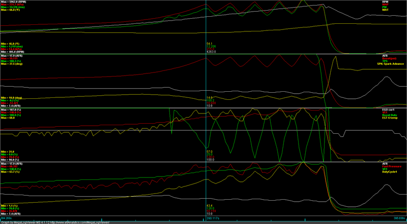
Before the supercharger belt gets installed, I need to fix boost control, which is now out of control. The target in the graph below, is 200kpa!
All with settings that worked fine last year.
When installing the belt, the belt seems to jam on the edges of the bracket. Once it's on, it's golden.

Now just have to wire in the additional temp sensor, and supercharger bypass valve and get the MS programmed for these 2 items.
Before the supercharger belt gets installed, I need to fix boost control, which is now out of control. The target in the graph below, is 200kpa!
All with settings that worked fine last year.

Reply
0
0
So I think you changed the exhaust, did you change anything else? It looks to me like you have closed loop activating before full spool and then too much P. I can maybe help you with this offline if you would like.
Reply
0
0

Thread Starter
Junior Member
Joined: May 2007
Posts: 340
Total Cats: 98
From: Toronto Area, Ontario
Thanks, posted.
Any suggestions are appreciated. You will note this tune is pretty rich. I added quite a lot of fuel after putting on the larger exhaust, and have not had a chance to pull any.
Reply
0
0


Changes were exhaust, and a change from a 3 to 4 way valve. Intake manifold changed too, but I am not sure that would have that much of an effect.
Thanks, posted.
Any suggestions are appreciated. You will note this tune is pretty rich. I added quite a lot of fuel after putting on the larger exhaust, and have not had a chance to pull any.
Thanks, posted.
Any suggestions are appreciated. You will note this tune is pretty rich. I added quite a lot of fuel after putting on the larger exhaust, and have not had a chance to pull any.
Reply
0
0
Thread Starter
Junior Member
Joined: May 2007
Posts: 340
Total Cats: 98
From: Toronto Area, Ontario
Man, I am so tired and sore. I need a day off to recover from the weekend!
I have heard from others who have twin charged their car, that boost control is a challenge. I don't quite understand why.
Pat -thanks for the file. I probably won't have the car back on the road till Wednesday for turbo only testing.
I need to make sure the electronics works perfectly out of the car first.
Reply
0
0
I don't think you will run into the same challenges with the architecture of your system. I regulate both the SC PR and the TC PR dynamically. ~I think~ your setup will allow for a set-it forget-it on the SC. Once the TC flow reaches a point where SC flow = TC flow you open your huge bypass (the TB) and then control with TC WG. The compound is pretty much handled automatically for you. I ~almost~ adopted this architecture with the version I am building now. Very compelling.
Reply
0
0
Thread Starter
Junior Member
Joined: May 2007
Posts: 340
Total Cats: 98
From: Toronto Area, Ontario
Got things back together tonight and loaded in these boost control setting. Logs attached.
With boost target set to 200KPI, boost runs straight up to 240KPA (4rth gear pull), which is the current over boost setting.
I also tried reducing the P with my previous set up, but probably reduced it too much (it overshot target by 20kpa, at which point I lifted). (didn't have much time, so need to hit this again tomorrow)
Ted
The people who told me boost control was a challenge when twin charging, were running the same set up as I am running.
I agree with you... Your setup is far more challenging which is one of the reasons I chose to go the simpler route.
Reply
0
0


