
TZ's build-a documentary of adequacy and hopes for more


Thread Starter
Elite Member
iTrader: (6)
Joined: May 2011
Posts: 1,656
Total Cats: 64
From: Albuquerque, NM
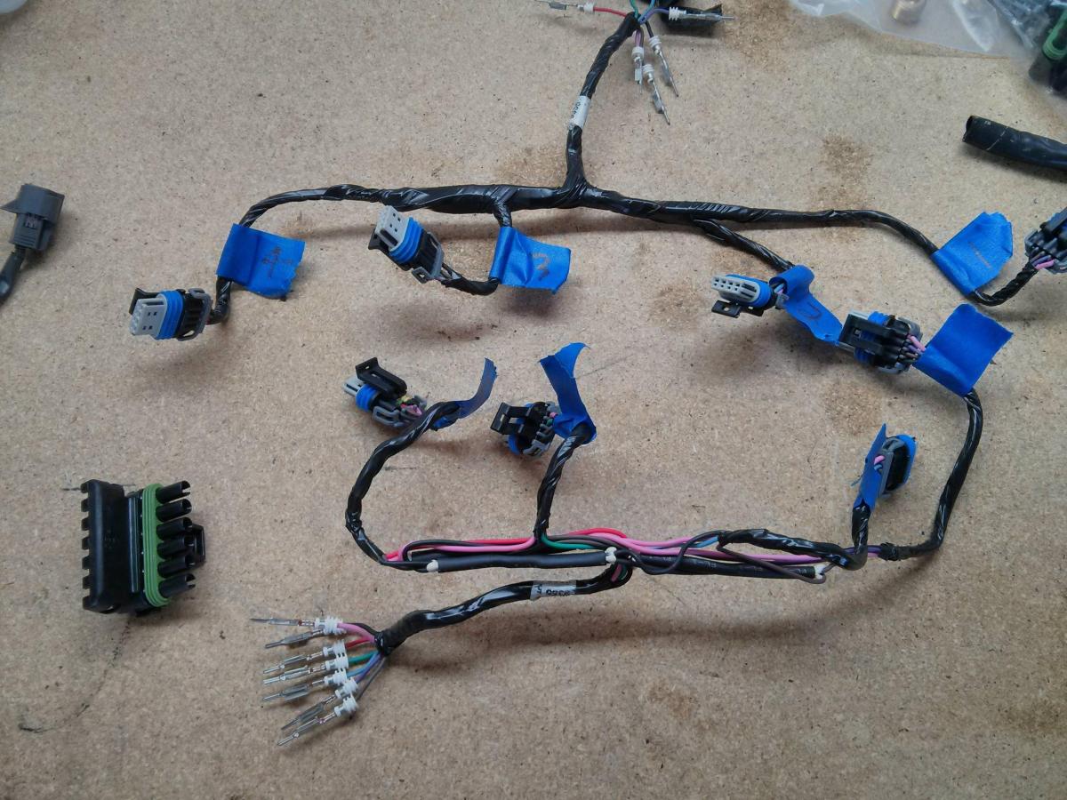
Messed with the ignition part of the harness a bit.
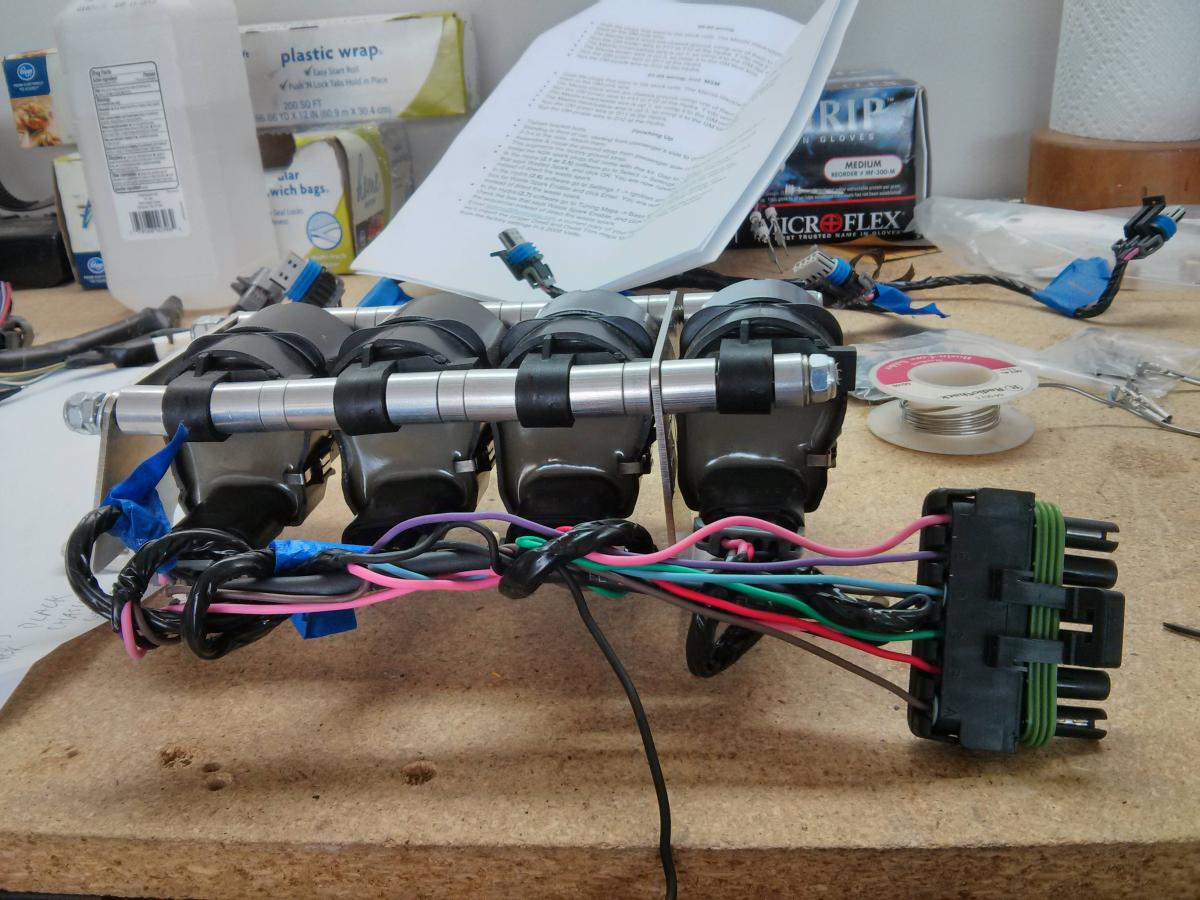
LS coil harness. Labeled what goes where and then clipped off the pins. Re-crimp on the weather pack connectors.
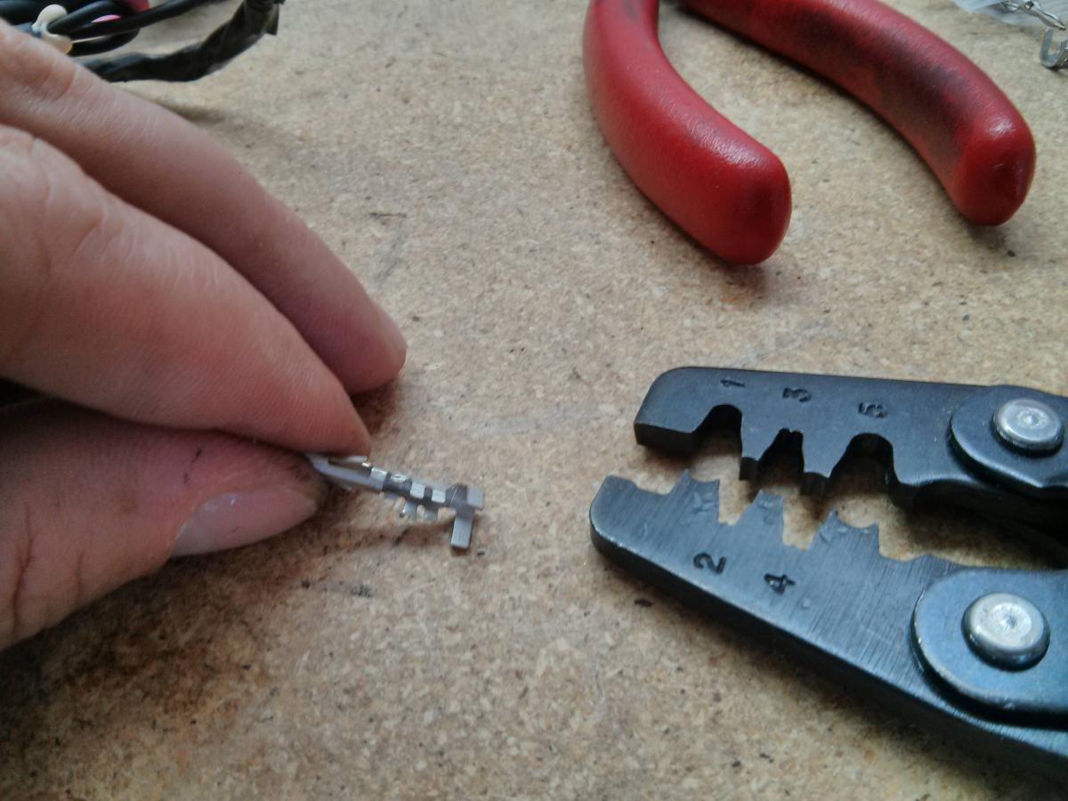
Make sure to only crimp the right spot. That first spot that looks like a mini crimp IS NOT a crimp. It keeps the pin from going all the way through the connector. If you crimp it the pin in the connector is sloppy like hooker. Ask me how I learned. For me it helps to U shape the weather pack crimps a bit. Out of the package they are more open like the top of a Y
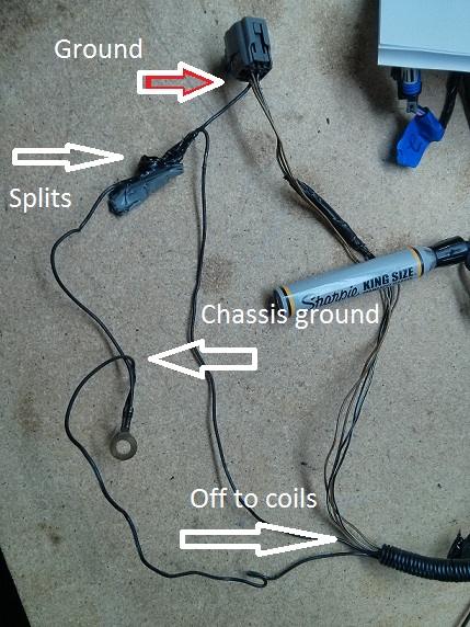
I need to redo the black wire to an eyelet. according to FM's wire directions the black is chassis ground. Brown is ECU ground. Not sure the difference. The factory I think uses the both together. Factory harness comes
--> through the connector --> chassis gounds itself --> then goes to coil
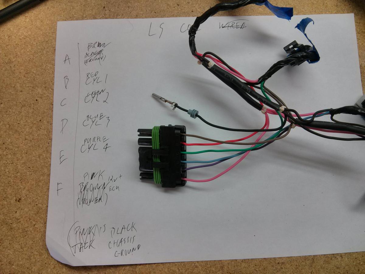
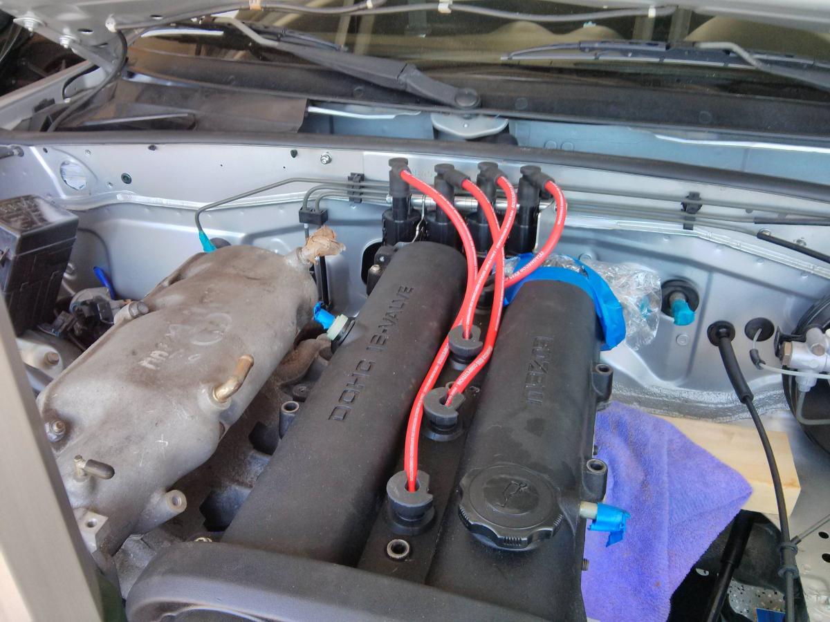
About where the connector sits
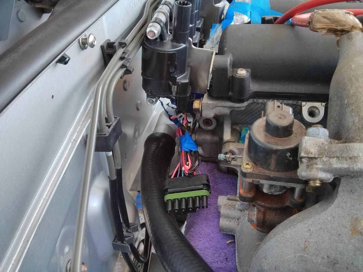
Ballpark of where wires and coils sit
Going to wrap it up later. Getting hot outside and need to figure out if I need to splice the Brown and Black wires to make a ground to ECU and chassis ground combined. Wiring Guru's Unite!
LS coil harness. Labeled what goes where and then clipped off the pins. Re-crimp on the weather pack connectors.
Make sure to only crimp the right spot. That first spot that looks like a mini crimp IS NOT a crimp. It keeps the pin from going all the way through the connector. If you crimp it the pin in the connector is sloppy like hooker. Ask me how I learned. For me it helps to U shape the weather pack crimps a bit. Out of the package they are more open like the top of a Y
I need to redo the black wire to an eyelet. according to FM's wire directions the black is chassis ground. Brown is ECU ground. Not sure the difference. The factory I think uses the both together. Factory harness comes
--> through the connector --> chassis gounds itself --> then goes to coil
About where the connector sits
Ballpark of where wires and coils sit
Going to wrap it up later. Getting hot outside and need to figure out if I need to splice the Brown and Black wires to make a ground to ECU and chassis ground combined. Wiring Guru's Unite!
Reply
 0
0

0

0-100 psi pressure 0-5V sensor I'm using as fuel pressure sender
Pressure Transducer or Sender 100 PSI for Oil Fuel Air | eBay
Pressure Transducer or Sender 100 PSI for Oil Fuel Air | eBay
Reply
0
0
Thread Starter
Elite Member
iTrader: (6)
Joined: May 2011
Posts: 1,656
Total Cats: 64
From: Albuquerque, NM
^thanks. I picked up a AEM oil one from the classifieds. I might get that for fuel. Not sure where to place it. I have FM's double rail. Maybe an inline -AN fitting at the Y spot.
Been going through wire diagrams. Trying to use the Mass Air wires for the oil temp. each have 3 wires and made sense.
MAF from left to right
white w/ red stripe----------------ECU ground
light green w/ black stripe---------ECU +12
black w/ blue stripe-----------------chassis ground

Coolant temp left to right
black w/red---------------ECU ground
purple w/white------------ECU +12
red w/blue----------------?????????

So shouldn't I wire it like so
Engine harness (MAF section)-------------Coolant temp (now oil temp)
light green w/black stripe-----------------purple w/white-------------ECU +12
white w/red------------------------------black w/red----------------ECU ground
black w/blue-----------------------------red w/blue-----------------stuff???????
These diagrams make me feel stupid. Miata Information and also found these https://www.miataturbo.net/engine-pe...ut-info-70052/
Been going through wire diagrams. Trying to use the Mass Air wires for the oil temp. each have 3 wires and made sense.
MAF from left to right
white w/ red stripe----------------ECU ground
light green w/ black stripe---------ECU +12
black w/ blue stripe-----------------chassis ground
Coolant temp left to right
black w/red---------------ECU ground
purple w/white------------ECU +12
red w/blue----------------?????????
So shouldn't I wire it like so
Engine harness (MAF section)-------------Coolant temp (now oil temp)
light green w/black stripe-----------------purple w/white-------------ECU +12
white w/red------------------------------black w/red----------------ECU ground
black w/blue-----------------------------red w/blue-----------------stuff???????
These diagrams make me feel stupid. Miata Information and also found these https://www.miataturbo.net/engine-pe...ut-info-70052/
Reply
0
0
MAF from left to right
white w/ red stripe - ECU +12
light green w/ black stripe - MAF signal
black w/ blue stripe - ECU ground
Coolant temp left to right
black w/red - ECU ground
purple w/white - Coolant gauge in cluster
red w/blue - Coolant temp signal
white w/ red stripe - ECU +12
light green w/ black stripe - MAF signal
black w/ blue stripe - ECU ground
Coolant temp left to right
black w/red - ECU ground
purple w/white - Coolant gauge in cluster
red w/blue - Coolant temp signal
Reply
0
0

Thread Starter
Elite Member
iTrader: (6)
Joined: May 2011
Posts: 1,656
Total Cats: 64
From: Albuquerque, NM
Yep. It's FM's LS coils bracket. For the LS3 coils they should all fit inside the side plates. These are LS2, to my knowledge (got sold the wrong thing), and are too wide to fit. Notice they are round. I used some stainless all thread to make two new rods. Then I had them send me the spacers for their big radiator fan panel. The big spacers on the rod are from the coil kit. The little ones are crossflow fan bracket spacers.
Also note that the bracket toward the middle of the head needs the bolt holed tab flipped 180deg. Not their faught. I Ebay'd the coils and ordered the bracket from FM. Ebay seller didn't make a decent add, +my ignorance on GM coils at the time, dumb crap ensued, and wasn't worth the hassle at the time.
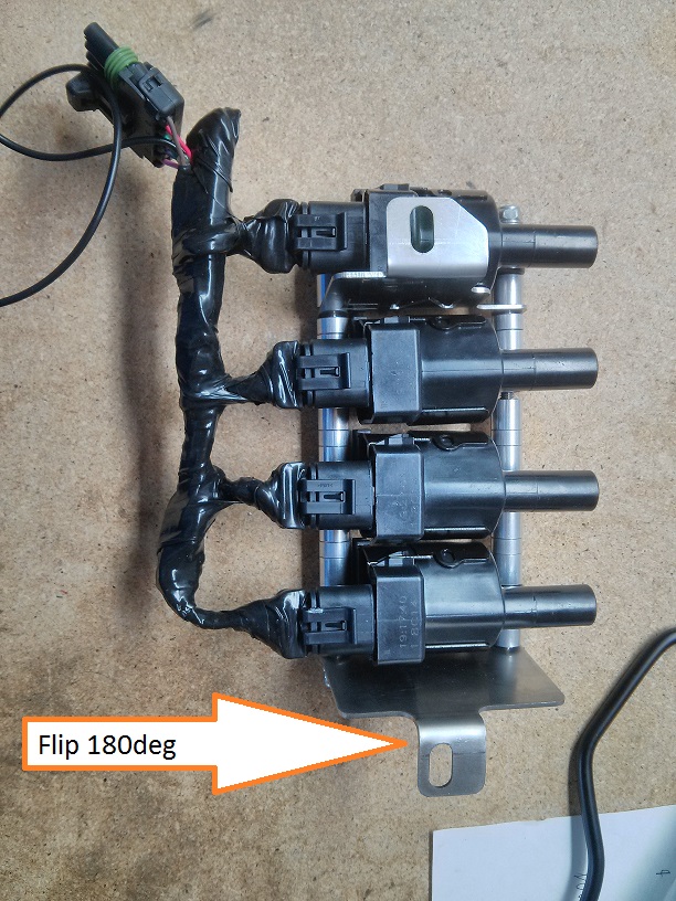
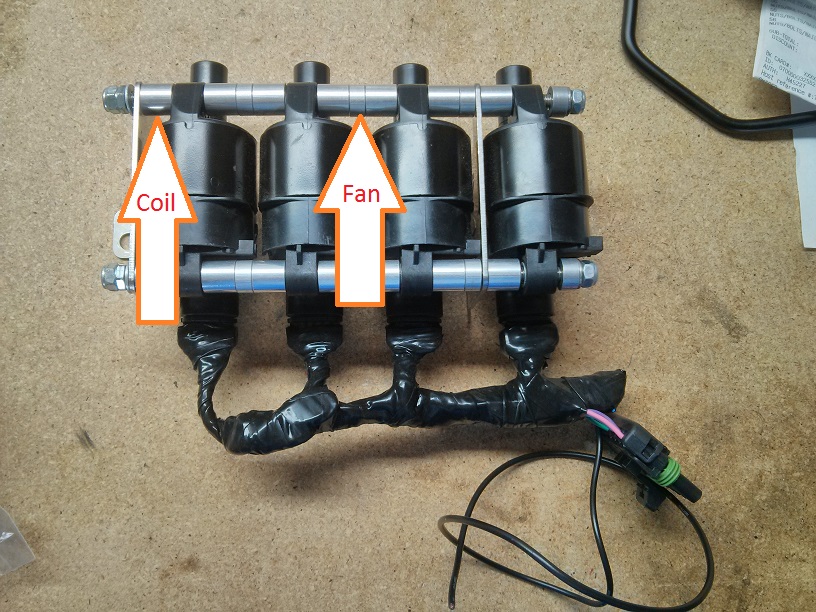
The silicon tape is awesome stuff as well.
Also note that the bracket toward the middle of the head needs the bolt holed tab flipped 180deg. Not their faught. I Ebay'd the coils and ordered the bracket from FM. Ebay seller didn't make a decent add, +my ignorance on GM coils at the time, dumb crap ensued, and wasn't worth the hassle at the time.
The silicon tape is awesome stuff as well.
Reply
1
1
Thread Starter
Elite Member
iTrader: (6)
Joined: May 2011
Posts: 1,656
Total Cats: 64
From: Albuquerque, NM
I just got my Rev build MS3 in today. The stock ECU spot under the column probably isn't going to happen. The thing is big. I'm thinking of sticking it behind the glove box similar to the FM Hydra setup.
It will fit here if I remove the rusty metal tab on the left. Mounting it is the next issue.
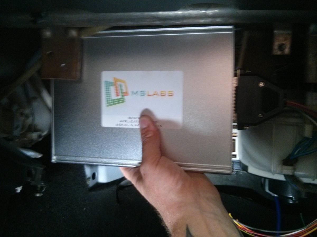
It will just fit between the A/C cross tube and the back of the glove box.
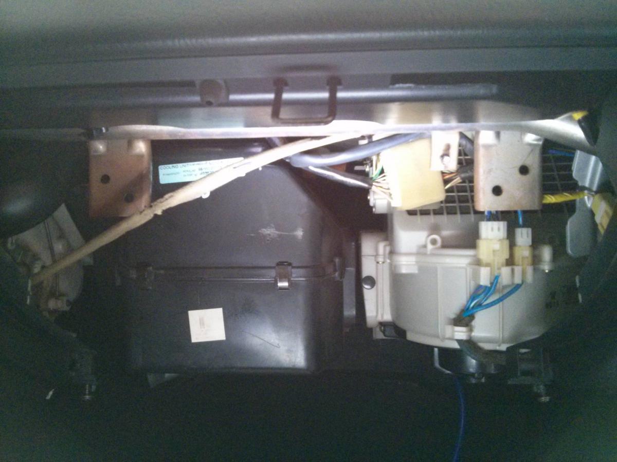
The issue is this connector will not reach. The factory engine harness, the left two connectors, will reach if pulled back through from behind the center dash it seems. Just the one connector that come from the chassis harness will never reach. Might call Boomslang and see what a 3ft extension would cost. The thing won't fit well under my seat unless you count sitting on the case okay. Thought behind the seat, but then I need an expensive harness extension and the MAP line will be run under the carpet, so that's a no go. Any other ideas welcome. Especially a way to mount it behind the glove box.
Also my modding the harness idea needs modified. I have no idea what I'm doing with MegaSquirt
It will fit here if I remove the rusty metal tab on the left. Mounting it is the next issue.
It will just fit between the A/C cross tube and the back of the glove box.
The issue is this connector will not reach. The factory engine harness, the left two connectors, will reach if pulled back through from behind the center dash it seems. Just the one connector that come from the chassis harness will never reach. Might call Boomslang and see what a 3ft extension would cost. The thing won't fit well under my seat unless you count sitting on the case okay. Thought behind the seat, but then I need an expensive harness extension and the MAP line will be run under the carpet, so that's a no go. Any other ideas welcome. Especially a way to mount it behind the glove box.
Also my modding the harness idea needs modified. I have no idea what I'm doing with MegaSquirt
Reply
0
0
I just got my Rev build MS3 in today. The stock ECU spot under the column probably isn't going to happen. The thing is big. I'm thinking of sticking it behind the glove box similar to the FM Hydra setup.
It will fit here if I remove the rusty metal tab on the left. Mounting it is the next issue.
It will just fit between the A/C cross tube and the back of the glove box.
The issue is this connector will not reach. The factory engine harness, the left two connectors, will reach if pulled back through from behind the center dash it seems. Just the one connector that come from the chassis harness will never reach. Might call Boomslang and see what a 3ft extension would cost. The thing won't fit well under my seat unless you count sitting on the case okay. Thought behind the seat, but then I need an expensive harness extension and the MAP line will be run under the carpet, so that's a no go. Any other ideas welcome. Especially a way to mount it behind the glove box.
Also my modding the harness idea needs modified. I have no idea what I'm doing with MegaSquirt
Reply
0
0
Thread Starter
Elite Member
iTrader: (6)
Joined: May 2011
Posts: 1,656
Total Cats: 64
From: Albuquerque, NM
I got a Boomslang extension for the one plug I need. FYI mine is 48in and could easily fit a 36in for others reference. I erred on the long side and 48 is really long. Safer than going to short.
Anyone see any issue with ziptying/velcroing the MS3 to the back of the glove box? Finding a hard mount to the dash bar may be beyond my fab skills. A welder would make life far easier. Curious if as long as the harness isn't getting pulled on would opening and closing the glove box hurt the ECU? Vibrations?
The other end is plugged in, then loomed behind everything in the dash, and there is tons of length. Sorry bad pick.
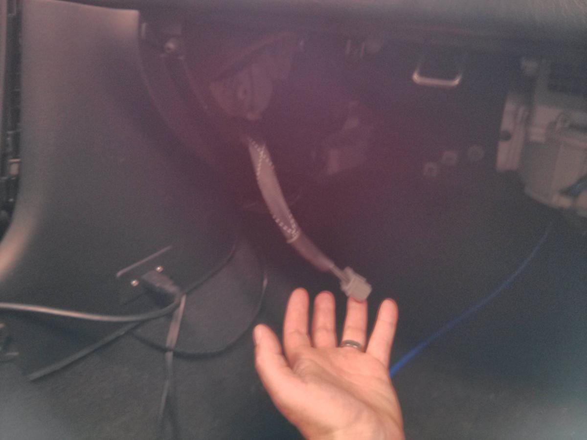
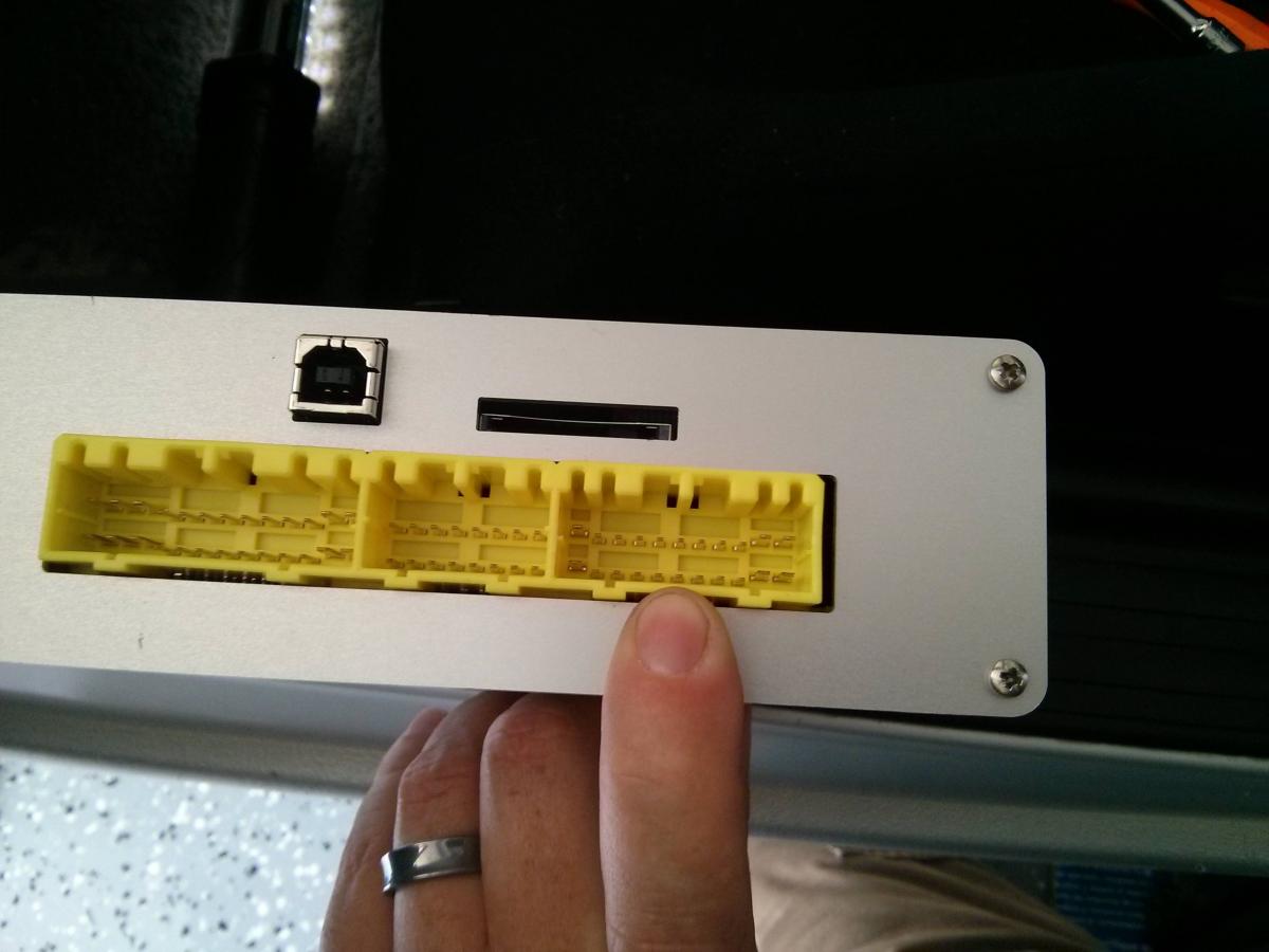
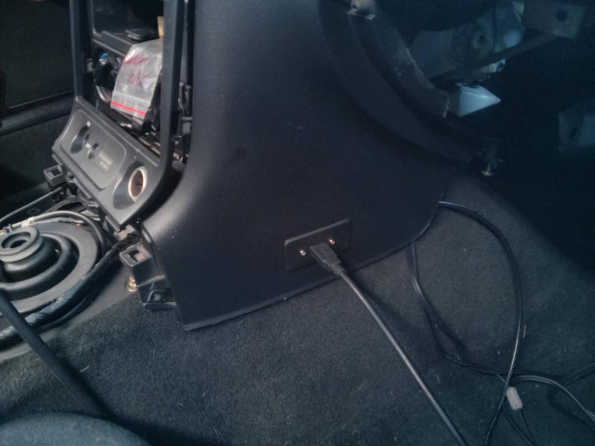
Decided I didn't want to dig around to plug into the ECU USB every time. So I found a USB to panel mount and placed it in the little removal panel by the passengers knee.
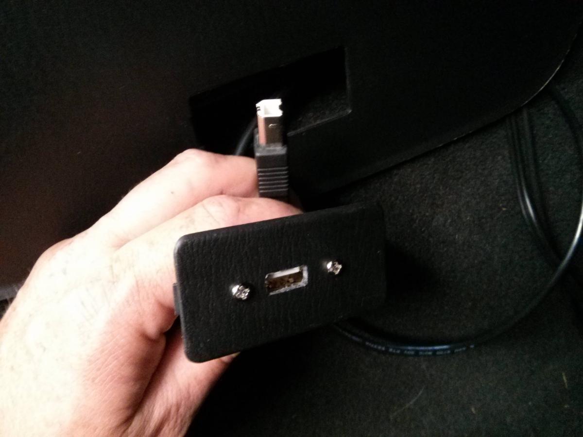
Might get a 90deg for it if it gets in the way. Plenty long and if it isn't than i can get longer leads.
Anyone see any issue with ziptying/velcroing the MS3 to the back of the glove box? Finding a hard mount to the dash bar may be beyond my fab skills. A welder would make life far easier. Curious if as long as the harness isn't getting pulled on would opening and closing the glove box hurt the ECU? Vibrations?
The other end is plugged in, then loomed behind everything in the dash, and there is tons of length. Sorry bad pick.
Decided I didn't want to dig around to plug into the ECU USB every time. So I found a USB to panel mount and placed it in the little removal panel by the passengers knee.
Might get a 90deg for it if it gets in the way. Plenty long and if it isn't than i can get longer leads.
Reply
1
1


Nice idea. I know they make 12v adapters and a lot of newer cars have usb ports for charging stations. I think I'd like to add a usb charging station to my console. Thanks for the simple but easily executable/useful idea.
I understand that's not what you're using it for but it sparked my light bulb. I bought the blue tooth adapter but if i hadn't. I'd probably be copying this. Like you said about getting a 90; I would have probably put that panel to the right of the shifter. That way it would be facing up and out of the way.
I understand that's not what you're using it for but it sparked my light bulb. I bought the blue tooth adapter but if i hadn't. I'd probably be copying this. Like you said about getting a 90; I would have probably put that panel to the right of the shifter. That way it would be facing up and out of the way.
Reply
0
0
Thread Starter
Elite Member
iTrader: (6)
Joined: May 2011
Posts: 1,656
Total Cats: 64
From: Albuquerque, NM
I threw it there cause it is a cheap easy panel to replace. Figured if I didn't like it it's easy to reverse, or swap a good plate in and move somewhere else. I'm already thinking I might move it to the center console cubby. I think I'm going to turn this build more toward fun, fast daily. Tablet in the dash with WiFi, Nav, hands free calling, etc. Actually starting to look into putting AC back in and cruise as well. Sorta curious if the cruise system out of my '97 M edition would work. Problem one is the Skunk throttle body doesn't have a spot for the extra cable.
Reply
0
0
Thread Starter
Elite Member
iTrader: (6)
Joined: May 2011
Posts: 1,656
Total Cats: 64
From: Albuquerque, NM
Semester started and project was tossed on hold. Also having some serious engine builder woes. I took a look at my wiring notes yesterday and I think I need to completely re imagine my idea. Keep in mind I have NO MS3 experience. I have the 30ish pin connector for the extra stuffs and the color coded notes from Rev. It looks like I would have to split the harness to that connector for some things. I was hoping I could just go into the "options" for the MS and tell it that the wires for the MAF are no longer that and tell it that MAF is now oil temp or pressure or ?. I though that since the factory harness was used the stuff like EGR could just be re purposed. Am I wrong? stupid? not looking at megatune right? I'm trying to minimize splices. I have another harness so it isn't a necessity to not hack it up, just want to minimize potential mistakes. I really wanted to have the other gauges displayed through the ECU itself. I feel the dumb.
Reply
0
0
Thread Starter
Elite Member
iTrader: (6)
Joined: May 2011
Posts: 1,656
Total Cats: 64
From: Albuquerque, NM
Well harness work is back on. Grabbed a spare scrap yard one to salvage wires from. I'm thinking of ordering a a small vdo temp gauge for oil temp. Also I see no reason to run two oil pressure sensors. Plans are to use this 150psi one I have (need to figure out exactly what it is) and sending the signal to both the gauge cluster and ecu. The gauge cluster doesn't have numbers on it so I don't care. I just want it to do something and drop when I have no pressure. Any suggestions for 12v 5amp switched power source? Need it for a few things and not super warm and fuzzy about using the same source for vvt, ebc, and others.
Reply
0
0
Thread Starter
Elite Member
iTrader: (6)
Joined: May 2011
Posts: 1,656
Total Cats: 64
From: Albuquerque, NM
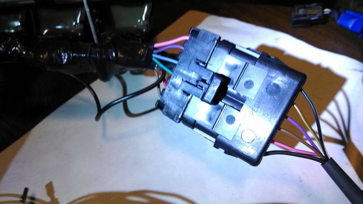
Got some time to work on the harness today. Ignition engine side is done. Trying to get the bay side done, leave pig tails ECU side for the DB connector, and then do the DB connector.
Here is the color chart I made. Should be relatively self explanatory.
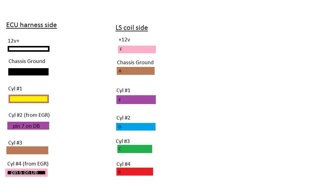
The connector. The light in my office is terrible, sorry for crap pics.
Here is the color chart I made. Should be relatively self explanatory.
The connector. The light in my office is terrible, sorry for crap pics.
Reply
0
0
Thread Starter
Elite Member
iTrader: (6)
Joined: May 2011
Posts: 1,656
Total Cats: 64
From: Albuquerque, NM
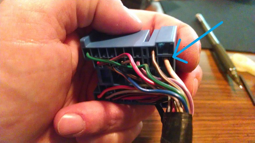
I need a +12volts source for the VVT, datalog start/stop, and EBC. I traced this white/red stripe wire from the MAF, VICS solenoid, and crank position sensor to a T-connection in the harness that goes to one wire and then to the blue connecter by the heater core. Am I safe to assume this is a +12v source I can use for VVT and EBC? Idea would be to hack off the MAF/VICS line and reroute to those.
Wires start here
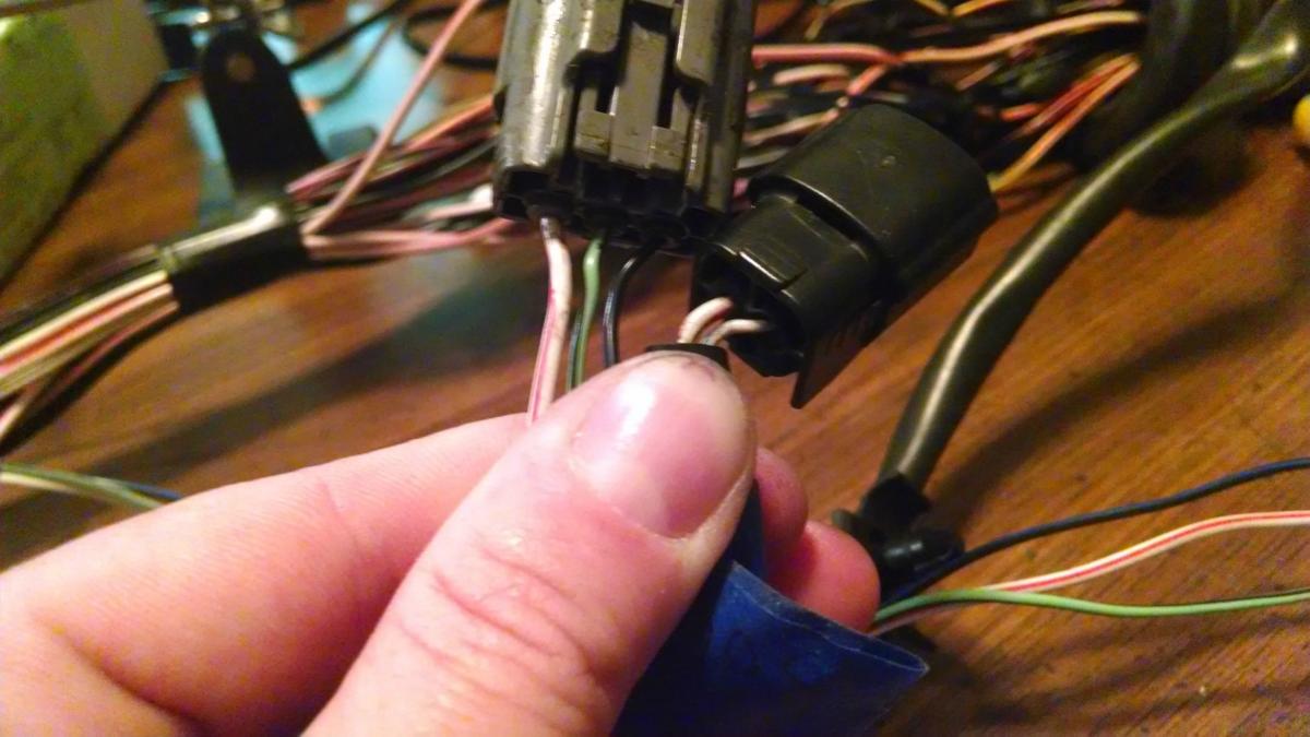
Merge together here under the dash somewhere.
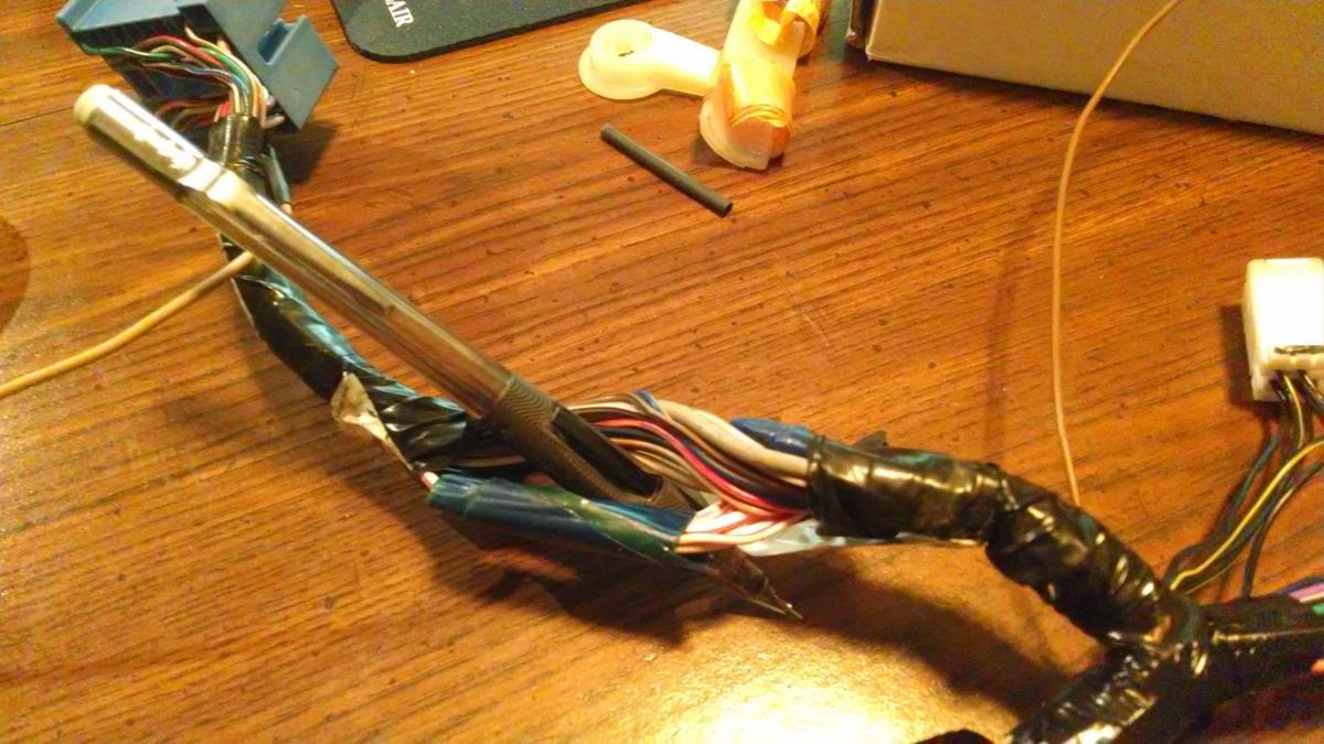
And then end here at he blue arrow
Wires start here
Merge together here under the dash somewhere.
And then end here at he blue arrow
Reply
0
0


