
ABSURDflow Turbo KLDE Mazda V6 Thread

Thread Starter

Joined: Jun 2006
Posts: 7,037
Total Cats: 425
From: Chesterfield, NJ
+Vs is +12VDC (well more like 14volts, whatever the alternator is making). When the gate is closed, no input signal from arduino, the Rc 1kohm allows the output signal to the pump to be 12vdc. When the input signal is given, the source and drain are connected and the output signal to the pump goes to ground. The Rc 1k resistor is so there is not a short to the +12V...?
And which is the source and drain on this diagram, or does it not matter? I assume B is the gate...
And the Rb 10kohm is so the MOSFET does not get too much current?
Reply
 0
0

0

Wait I think I get it. The bottom line is all ground, when I first looked at it I thought the input signal went to both circles at the left.
+Vs is +12VDC (well more like 14volts, whatever the alternator is making). When the gate is closed, no input signal from arduino, the Rc 1kohm allows the output signal to the pump to be 12vdc. When the input signal is given, the source and drain are connected and the output signal to the pump goes to ground. The Rc 1k resistor is so there is not a short to the +12V...?
And which is the source and drain on this diagram, or does it not matter? I assume B is the gate...
And the Rb 10kohm is so the MOSFET does not get too much current?
E= emitter, B = base, C= collector.
Reply
0
0
Thread Starter
Joined: Jun 2006
Posts: 7,037
Total Cats: 425
From: Chesterfield, NJ
You got right how it works, but what is used here is a standard transistor, not a MOSFET. Don't see why you should spend more money on a MOSFET, when a simple 2N2222or some such will do.
E= emitter, B = base, C= collector.
E= emitter, B = base, C= collector.

This one has a bunch of 2's in it's part number:
http://www.radioshack.com/product/in...ductId=2062608
Reply
0
0

they are in this pack:
http://www.radioshack.com/product/in...ductId=2062586
but what you psoted is close enough, just rated at 650mA vs 1A.
http://www.radioshack.com/product/in...ductId=2062586
but what you psoted is close enough, just rated at 650mA vs 1A.
Reply
1
1
Thread Starter
Joined: Jun 2006
Posts: 7,037
Total Cats: 425
From: Chesterfield, NJ
Wait, what? I can't have this ---- blow up. If the circuit fails, pump will turn off, engine will fail, life will fail.
I'll probably have a separate regular ol' relay that bypasses this Arduino signal with a 100%DC for maximum flow rate, triggered manually with a switch or the AEM based on CLT as a safety measure. hell, even the radiator fan power can trigger the relay if need be, but I'll probably have it triggered 5-10 deg higher. This pump supposedly flows a bunch, I doubt I'll ever need max flow rate.
I'll probably have a separate regular ol' relay that bypasses this Arduino signal with a 100%DC for maximum flow rate, triggered manually with a switch or the AEM based on CLT as a safety measure. hell, even the radiator fan power can trigger the relay if need be, but I'll probably have it triggered 5-10 deg higher. This pump supposedly flows a bunch, I doubt I'll ever need max flow rate.
Reply
0
0
Thread Starter
Joined: Jun 2006
Posts: 7,037
Total Cats: 425
From: Chesterfield, NJ
OK the resistor feeding the base of the 2N2222A should be 1kohm like Jason said or 10kohm like the diagram?
EDIT: little jobbies like this or do I need something more substantial?
http://www.radioshack.com/product/in...ductId=2062343
.25 wattmax @ 12v is .020 amps max, * 1000 ohms is 20volts max, so I should be cool with those I'd guess...?
EDIT AGAIN:
http://www.radioshack.com/product/in...ductId=2062323 these are local and 1/2 watt for the same price.
Reply
0
0
Thread Starter
Joined: Jun 2006
Posts: 7,037
Total Cats: 425
From: Chesterfield, NJ
http://www.radioshack.com/product/in...ductId=2062617
TIP120 is $2 at the local store, 125 isn't found. If the 120 is better than the 2N2222A, I'd go with that, $2 is not much.
TIP120 is $2 at the local store, 125 isn't found. If the 120 is better than the 2N2222A, I'd go with that, $2 is not much.
Reply
0
0
it's much better. can handle like 8A and dissapate 85watts vs. 600mA and 625mW of dissipation.
both NPN transistors. I used both in my megasquirts. the Pn2222 when just powering a relay of sorts, the tip120 when needing to control something PWM such as my idle valve or boost solenoid.
both NPN transistors. I used both in my megasquirts. the Pn2222 when just powering a relay of sorts, the tip120 when needing to control something PWM such as my idle valve or boost solenoid.
Reply
0
0
I'd go with the 1KOhm resistor for the base. The same for the pull-up, so you only need one value.
The blowing up of transistors usually happens when I try the circuits out and have a fail in the design. Once you have them working and nothing gets terribly hot, they usually don't blow up any more!
Remember, if you go with this circuit, your PWM will be reversed. When the output on the Arduino goes high, the output of your circuit goes low.
For the output, I would go with something like:
Base_minimum = 128 (for example, meaning you never go below 50% duty cycle)
P_value = (CLT_Value + Offset) * gain
IF P_value > Base_minimum THEN P_value = Base_minimum
Output value = Base_minimum - P_value
So the larger your P_value gets, the lower your Output_value gets.
Not sure how Arduino handles negative values when calculating bytes, so I added the safety with the "IF" clause. Your result should never be less than 0 this way.
CLT_value might need a minus, depending how the voltage measured changes with temperature (not sure if coolant sensors are NTC or PTC).
But none of this is verified, so please make sure that this makes sense before you blow up your engine because of it!
Arduinos are really quite safe btw, so I wouldn't worry about a safety override with the relay. Safe weight :-)
If you want a safety device, it would be better applied to the base of the transistor, where currents are small. If you apply 0V directly to the base of the transistor (by whatever means, even a simple switch, or an output from a Megasquirt), the transistor will go "open" and you'll have a 100% duty cycle at your pump, no matter what the Arduino says.
Reply
1
1
Thread Starter
Joined: Jun 2006
Posts: 7,037
Total Cats: 425
From: Chesterfield, NJ
If you apply 0V directly to the base of the transistor (by whatever means, even a simple switch, or an output from a Megasquirt), the transistor will go "open" and you'll have a 100% duty cycle at your pump, no matter what the Arduino says.
Reply
0
0
But almost postive when I build that in MS for the tachout it's a 1K on the input and a 1K pullup on the output.
I need to go back and read what signals you need, and what not, i havent followed this well.
Reply
0
0
Thread Starter
Joined: Jun 2006
Posts: 7,037
Total Cats: 425
From: Chesterfield, NJ
I picked up the circuit components at radio shack and have the LCD on order from amazon, $10 win. Thanks fellas!!!!!
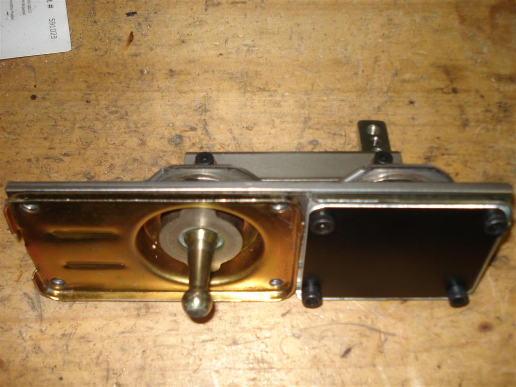
Paging thru MotoIQ's site I saw their LS3 RX7 build which I haven't seen yet. One of the title pictures is this sexy bitch. Looks sorta familar. Mine is much simpler & cheaper not having to worry about designing & buying the pivot *****, but if money & time were no object I'd do it like this.

Mine again:
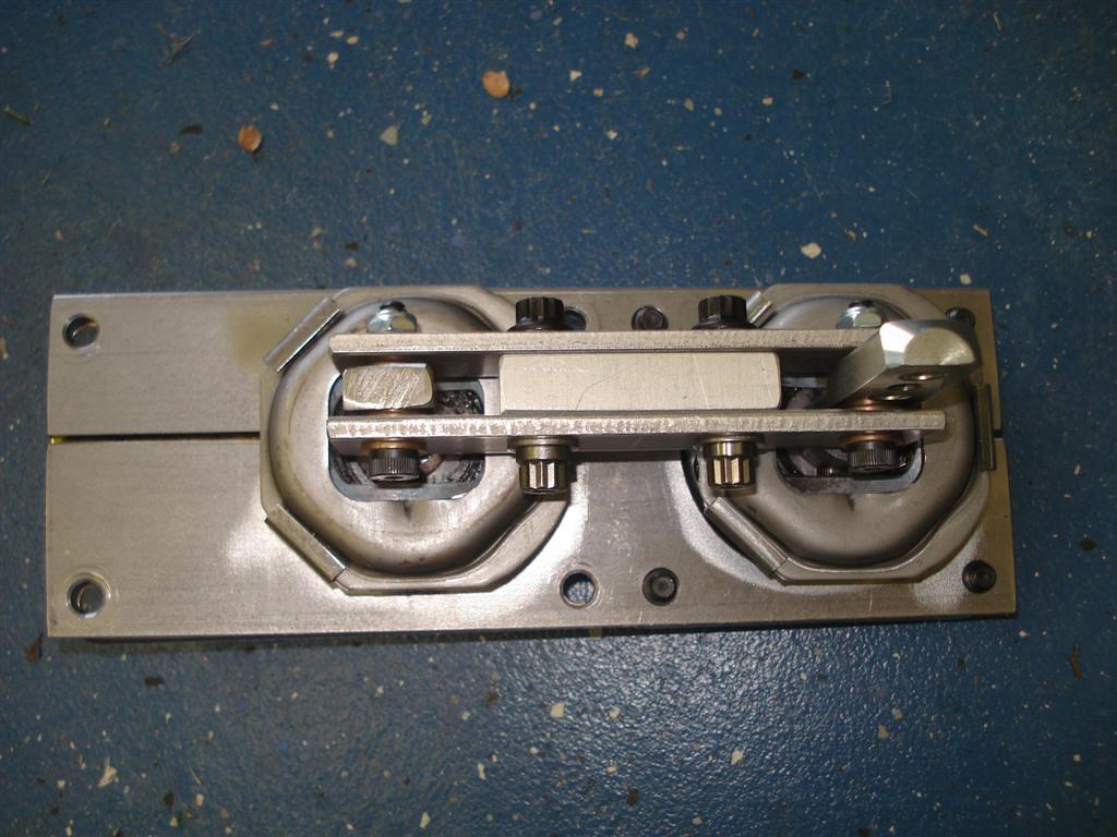
I finished the upper bolt-on shifter handle yesterday after welding the top portion of my original shifter onto a stalk I machined during lunch. Feels great, throw seems as short as the old raised-fulcrum short throw 5speed miata shifter. Actually, the springs that reset the shifter to center could be stiffer. I removed some of the spring from the front shifter figuring twice the spring would be bad, but with all the spring in the rear portion and half in the front (they are little leaf springs stacked up), it's softer than the old miata shifter. Oh well, not worth taking it all apart again. Pics eventually.
Paging thru MotoIQ's site I saw their LS3 RX7 build which I haven't seen yet. One of the title pictures is this sexy bitch. Looks sorta familar. Mine is much simpler & cheaper not having to worry about designing & buying the pivot *****, but if money & time were no object I'd do it like this.
Mine again:
I finished the upper bolt-on shifter handle yesterday after welding the top portion of my original shifter onto a stalk I machined during lunch. Feels great, throw seems as short as the old raised-fulcrum short throw 5speed miata shifter. Actually, the springs that reset the shifter to center could be stiffer. I removed some of the spring from the front shifter figuring twice the spring would be bad, but with all the spring in the rear portion and half in the front (they are little leaf springs stacked up), it's softer than the old miata shifter. Oh well, not worth taking it all apart again. Pics eventually.
Reply
0
0

Thread Starter
Joined: Jun 2006
Posts: 7,037
Total Cats: 425
From: Chesterfield, NJ
Yeah, two stock mustang shifters. One came with the transmission, the other was a take off from someone using a billet shifter. Some stainless bar I had lying around, graphite/bronze bushings and some shoulder bolts.
Reply
0
0

Thread Starter
Joined: Jun 2006
Posts: 7,037
Total Cats: 425
From: Chesterfield, NJ
Circuit guru's:
Can I get a schematic that shows how to hook up the OEM temperature sensor to an analog input on the Arduino? I assume it is a resistor that varys according to temperature. OEM has one wire going to ground, the other to the ECU. I will be using a dedicated sensor just for the Arduino. The Arduino wants to see varying voltage from 0-5volts. So I need a circuit that varys voltage from 0-5v when resistance changes.
I'm sure it's simple. Thanks
Reply
0
0

http://arduino.cc/playground/ComponentLib/Thermistor
There's the circuit and a nice explanation of how to use thermistors with arduino. The only kicker is, you need to swap that 10k resistor for something appropriate because I'm betting that the CLT sensor isn't a 10k thermistor. This page has helped me a lot. I'm currently trying to build an intercooler temp gauge with a GM IAT and an arduino, well.. Teensy 2.0, an off shoot based on arduino. So, in my project I measured the resistance of the sensor at room temperature and it was about 2.2k ohms, so I went with that resistor and it seems to put 80* ish F right around the middle of the ADC count in arduino.
There's the circuit and a nice explanation of how to use thermistors with arduino. The only kicker is, you need to swap that 10k resistor for something appropriate because I'm betting that the CLT sensor isn't a 10k thermistor. This page has helped me a lot. I'm currently trying to build an intercooler temp gauge with a GM IAT and an arduino, well.. Teensy 2.0, an off shoot based on arduino. So, in my project I measured the resistance of the sensor at room temperature and it was about 2.2k ohms, so I went with that resistor and it seems to put 80* ish F right around the middle of the ADC count in arduino.
Reply
0
0


