When you click on links to various merchants on this site and make a purchase, this can result in this site earning a commission. Affiliate programs and affiliations include, but are not limited to, the eBay Partner Network.
Got some Kraken goodies for my build yesterday and was able to hang the turbo for the first time! Got the full 3” option from him, absolutely top notch
Next is getting my oil and coolant lines ran, I am still waiting for my skunk2 intake to refund from TCSAutomotive as they closed and haven’t shipped my item ordered Dec 4th, but hopefully can order from somewhere else and finish the intake side and put it back in the car!
About the car, I’ve had it since Dec 2016 and got with 25k on the clock already turboed with a journal t25 and an MS1 setup
currently with 34k on the clock and a full built engine, last thing I need is to source my MS3 when funds allow
Very excited to almost be ready to go back in the car! A couple small things to figure out from here, but we are getting there
trying to figure out my EFR clocking location, last setup the t25 outlet was pointing straight down and massaged the shelf to for it and the EFR looks to be close to the same location, but I’ve seen a couple setups where it was clocked towards the block 25 degrees or so with a silicon 45 at the outlet... anyone have any pictures of their kraken efr setup?
This is nearly an exact copy of what I've been working on, minus your ATI damper, I'm not that baller. I pointed the housing towards the fender, and used a 2.5" hole saw to put the charge pipe behind the fender. I can post some pictures later, it leaves lots of room for any PS/AC you might have.
Also, do yourself a favor and put in a new front crank seal in the boundary pump, if you haven't already. I've so far seen 100% failure rate with the seals they send with the pump on the ~2 dozen pumps I've installed.
Nice! By the looks of it you put a new oil pump. Did you change the piston rings and crank bearings as well?
Oh yes, had a local machine shop do rods, pistons, rings, polish the crank (needed it), new ACL bearings, balance the assembly, and assemble the bottom end. I am somewhat mechanically inclined, but I recognize my limitations and bearing clearances fall well within my "not confident" zone. Assembled with ARP hardware throughout, had the BP4W head rebuilt with volvo springs, new guides, a light port and polish.
Curly:
"This is nearly an exact copy of what I've been working on, minus your ATI damper, I'm not that baller. I pointed the housing towards the fender, and used a 2.5" hole saw to put the charge pipe behind the fender. I can post some pictures later, it leaves lots of room for any PS/AC you might have.
Also, do yourself a favor and put in a new front crank seal in the boundary pump, if you haven't already. I've so far seen 100% failure rate with the seals they send with the pump on the ~2 dozen pumps I've installed."
Yes somebody cued me into the front seal issue before it was too late, so I put a Mazda OE one in before I did the damper (thankfully! I would have been so disappointed to find a leak up there once its running)
As far as the piping, I wont go through the fender mostly because I am trying to reuse as much of my intercooler setup before as possible, which utilize the FM silicon piping with the outlet facing directly down... I am hoping this setup will be somewhat close to the same location to make that piece work, even if I have to get creative. No AC but keeping PS
Haven't installed the EFR yet, but sounds like we have nearly identical builds. I'd recommend giving soviet's build thread a read. He's' one of the first guys to run EFR and lots of great info on there + I've laughed a few times reading it.
Once the turbo and intercooler piping is in place you'll be able to see how the compressor housing should be clocked. I had the same manifold but with a garrett turbo and it was pointing down slightly toward the engine block (7 o'clock).
Haven't installed the EFR yet, but sounds like we have nearly identical builds. I'd recommend giving soviet's build thread a read. He's' one of the first guys to run EFR and lots of great info on there + I've laughed a few times reading it.
Awesome, I have seen a bunch of Soviets posts and youtube dyno runs, but had actually never went through his full build thread.... definitely something to do on a slow day at work today! Would love to see 4xx on the dyno, though I think I would keep it in the 350s range just for a margin of safety on the rest of the drive line. Do I have that much self-control? IDK hahah. I talk about emotional regulation, rationality, and exercising self-control as a psychologist all day long, but totally recognize my limits in those areas when we starting talking about boost, more boost, and all-of-it
Originally Posted by Pepovr
Once the turbo and intercooler piping is in place you'll be able to see how the compressor housing should be clocked. I had the same manifold but with a garrett turbo and it was pointing down slightly toward the engine block (7 o'clock).
So thats kind of what I had seen, the EFR clocked at about 7 o'clock and then a 45degree silicone adapter should put it *about* in the same area as the silicone charge pipe I already have. I hope I can get my intake soon and get the block back in the car to see for sure -- the question is really whether it will clear where I already massaged the engine bay to fit the other turbo or not. I havent seen any other top mount EFR setups in this orientation, so I would guess not... but I am still going to try. I will post pictures when I get there as reference for others in the same boat in the future
Identical plans here minus the consideration of self-control.
For my IC routing, I did what curly was suggesting. no going back after cutting, but imo it's the best routing option. I believe hornetball was one of the first guys to put up pics of it. https://www.miataturbo.net/build-thr...0/#post1252898
Familiar with that setup; it certainly works but I disagree on it being “best”, my other setup and what I am trying to run here is less piping, no hole cutting, and I already have most of the materials. Not knocking your setup, it most certainly works and is a good option for many, but 100% not the route I’m taking.
I look forward to seeing what kind of numbers the setups put down and how they compare... you know, for science...
Take my "best" with a grain of salt. I mainly say that due to a smooth airflow (45 is my biggest bend) and only marginally longer routing but I really don't see it making any noticable difference over your routing. Realistically as long as your piping gets from A to B without going through the trunk and looking like a Japanese touge run, you're golden. If that downwards routing clears fine, I might actually switch for asthetics
Made some progress today and finally got my skunk2 manifold - my wife had ordered one from TCSAutomotive back in December and they closed and never shipped it so had to file a dispute; anyways finally got it today and slapped it on
and also had my friend Stefan from Napp Motorsports (lots of Miata related YouTube stuff, 7163 k24 Miata coming together) come help with some custom AN oil drain and coolant supply hoses and I’m so happy with how they came out... final oil supply and coolant return will be decided once the engine goes back into the car, which should be pretty soon!!
I still need to figure out some of my fuel stuff, but will get there once it’s back in. The skunk intake makes that stuff fairly accessible 👍🏻
what’s funny is that whoever did the old setup ran the oil feed from a T off the oil pressure sender and both ports on the exhaust size were unused
This is what happened to me too. I just installed a turbo setup on my car and tan my oil feed off the mishimoto sandwich plate, and as I’m installing the stuff I see the oil feed port by the dip stick. Thanks to tons of misinformation on the interwebs. I would change it but this car is getting a VVT engine in a few months so I might as well just leave it as is and reuse these parts on that engine
Stefan from Napp Motorsports and my other friend with a really clean rotrex build came and got the engine back in the car! Gives me lots of little things to get figured out, hoping to get the trans in next weekend. Had to trim a little of the ledge to clear the EFR and I have to rotate the power steering right at the banjo bolt ever so slightly, but overall an easy process with the chain-fall coming straight down
This is nearly an exact copy of what I've been working on, minus your ATI damper, I'm not that baller. I pointed the housing towards the fender, and used a 2.5" hole saw to put the charge pipe behind the fender. I can post some pictures later, it leaves lots of room for any PS/AC you might have.
Also, do yourself a favor and put in a new front crank seal in the boundary pump, if you haven't already. I've so far seen 100% failure rate with the seals they send with the pump on the ~2 dozen pumps I've installed.
This quite literally JUST happened to me. Very frustrating given the price of the pumps, should've done more research I suppose.
Originally Posted by Dr.Sep
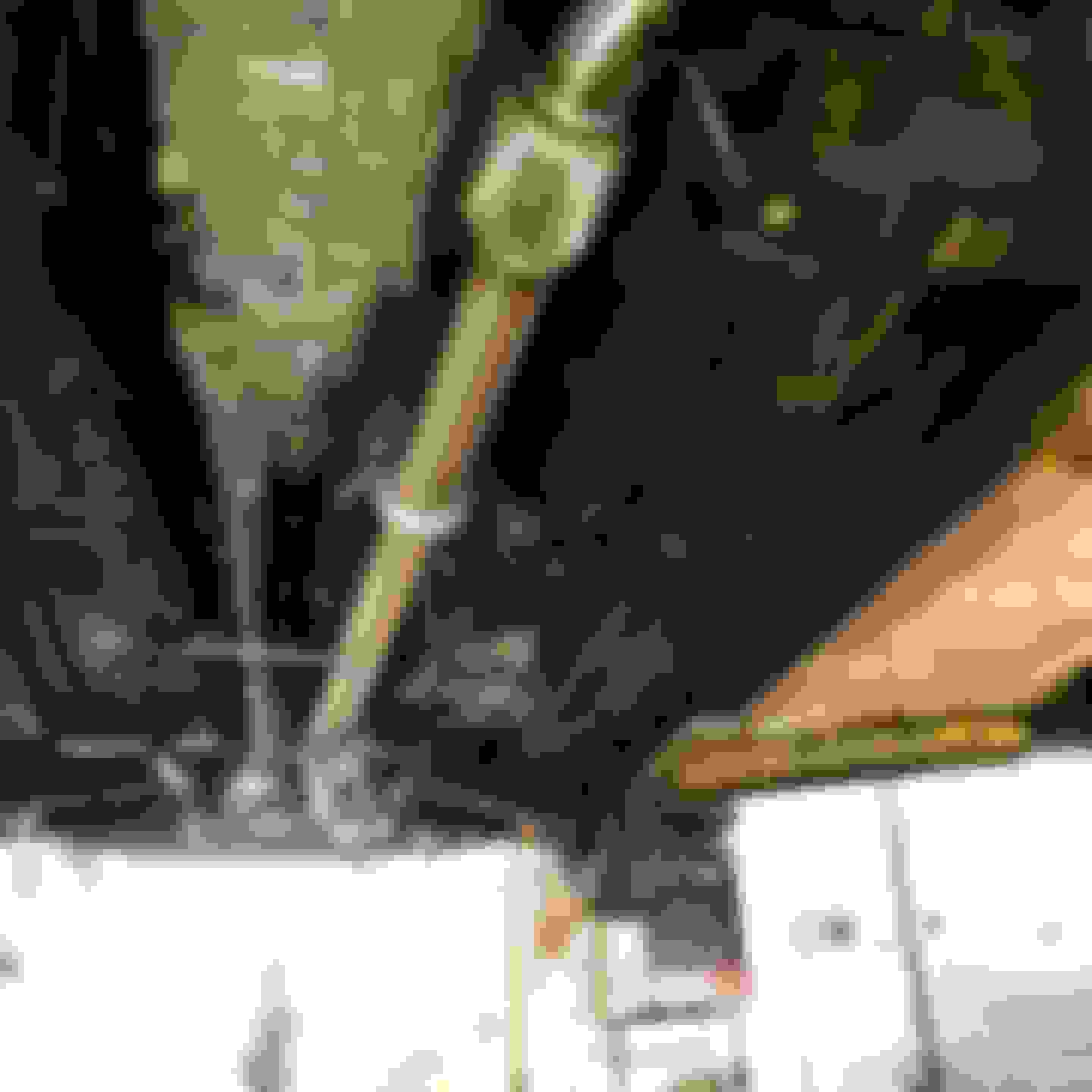
Better shot of the lines, though the turbo feed isn’t finalized - just got the right fitting for the top tonight, so I will get that closer tomorrow
I also take it that the black braided line from the block is a coolant feed? I had no idea they had one there although I did take advantage of the oil feed in that spot on my 95. Curious because I am planning on switching to an EFR as soon as funds allow and have been debating on where to pull coolant from since I've deleted the front coolant neck like you. Pretty sweet build though, pretty much either exactly what I have or exactly what I want.
This quite literally JUST happened to me. Very frustrating given the price of the pumps, should've done more research I suppose.
I also take it that the black braided line from the block is a coolant feed? I had no idea they had one there although I did take advantage of the oil feed in that spot on my 95. Curious because I am planning on switching to an EFR as soon as funds allow and have been debating on where to pull coolant from since I've deleted the front coolant neck like you. Pretty sweet build though, pretty much either exactly what I have or exactly what I want.
Yep, super convenient coolant feed! And since I deleted the front water neck, I am using that port off the coolant mixing neck as my turbo coolant return. Thank you though, I’m super stoked on the build and can see the light at the end of the tunnel... and spring is coming quick!
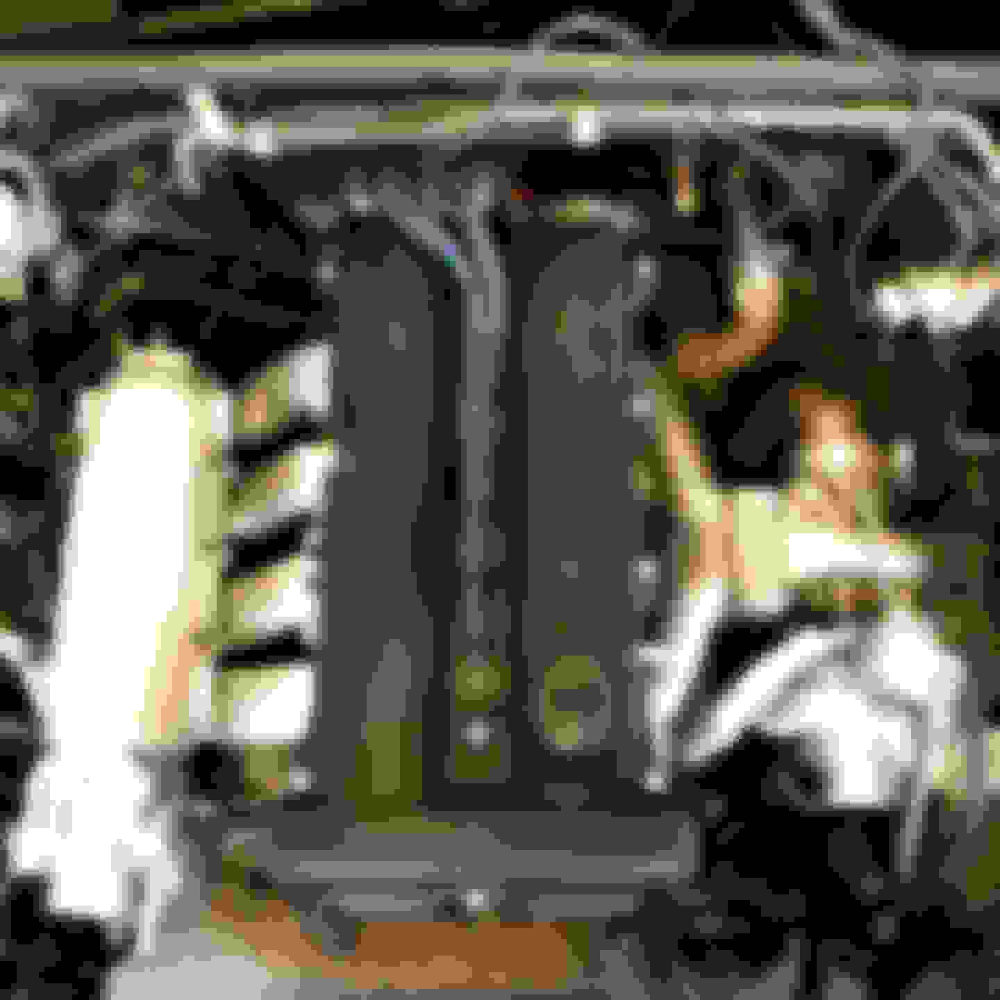
Whew, what a view ACT 6 puck and xtreme pressure plate (had to find my own m8-1.00x20mm and washers for the pressure plate this week) 6 speed, driveshaft, and the beautiful kraken 3” stainless exhaust hung Mint. Got a heat sheath for my oil feed, shouldddd be enough clearance but might make a bracket to hold it away from the manifold a little more No clearance issues, shelf unmodified
The Kraken stuff is absolutely amazing, really great kit that fit perfectly and looks outstanding.
Getting closer! Got a radium rail this week so going to start figuring my fuel side out
but a lot of stuff I can start putting back together now, and have a week off of work coming up, so hoping to get a lot done!
 01-19-2021, 06:14 AM


 3
3