When you click on links to various merchants on this site and make a purchase, this can result in this site earning a commission. Affiliate programs and affiliations include, but are not limited to, the eBay Partner Network.
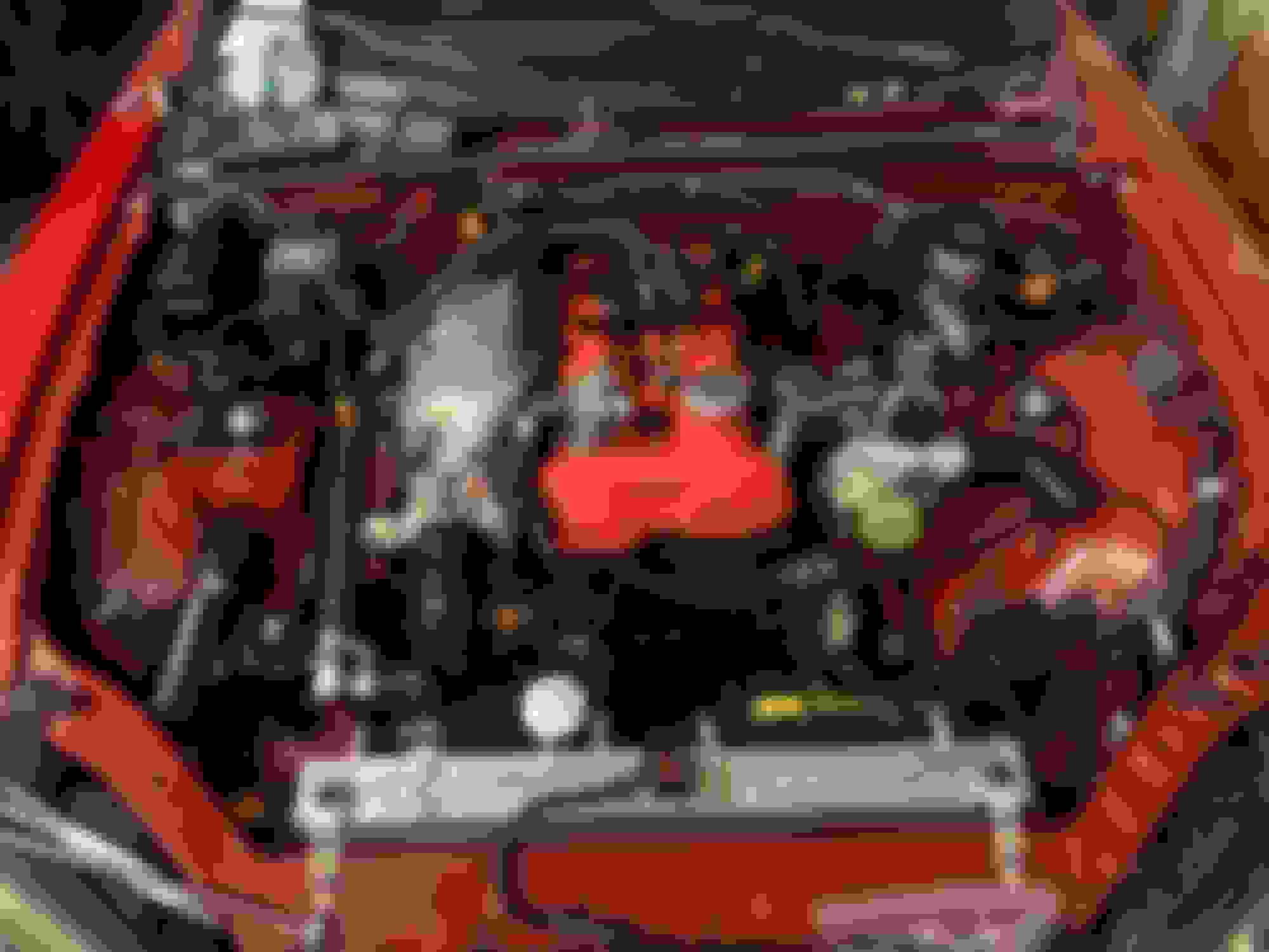
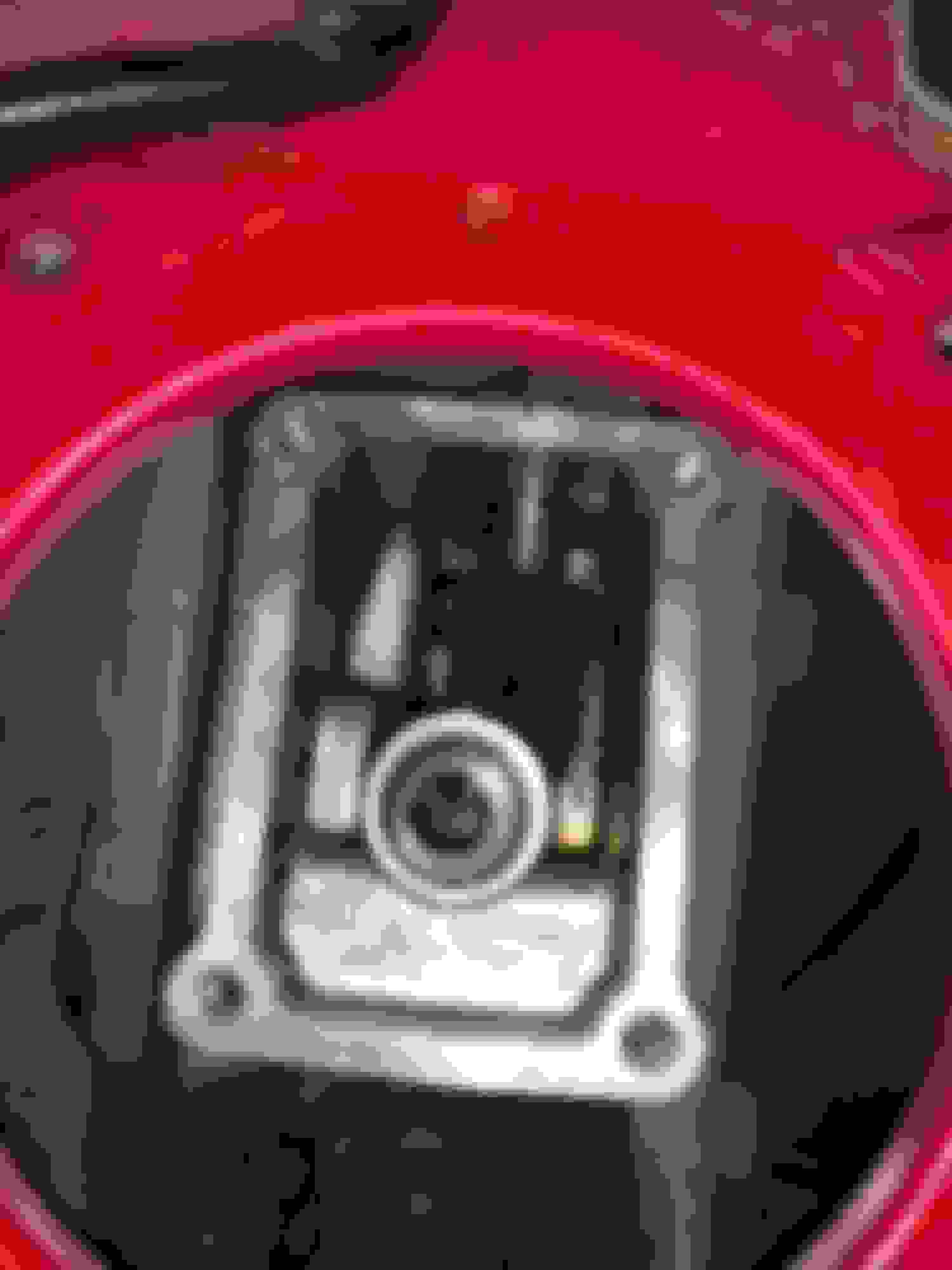
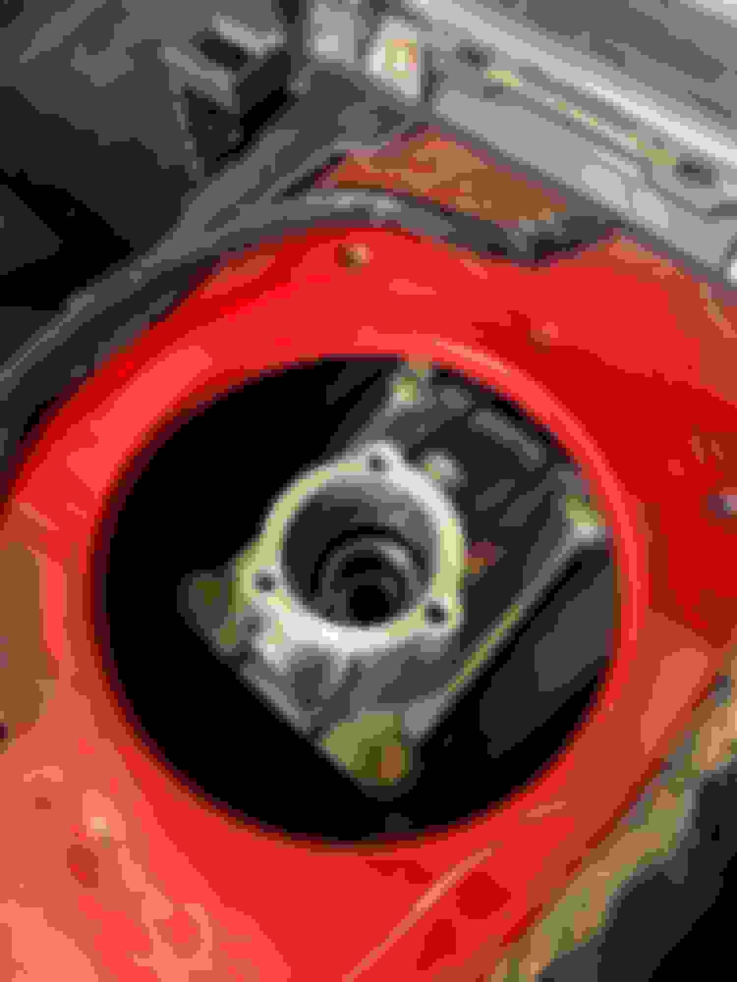
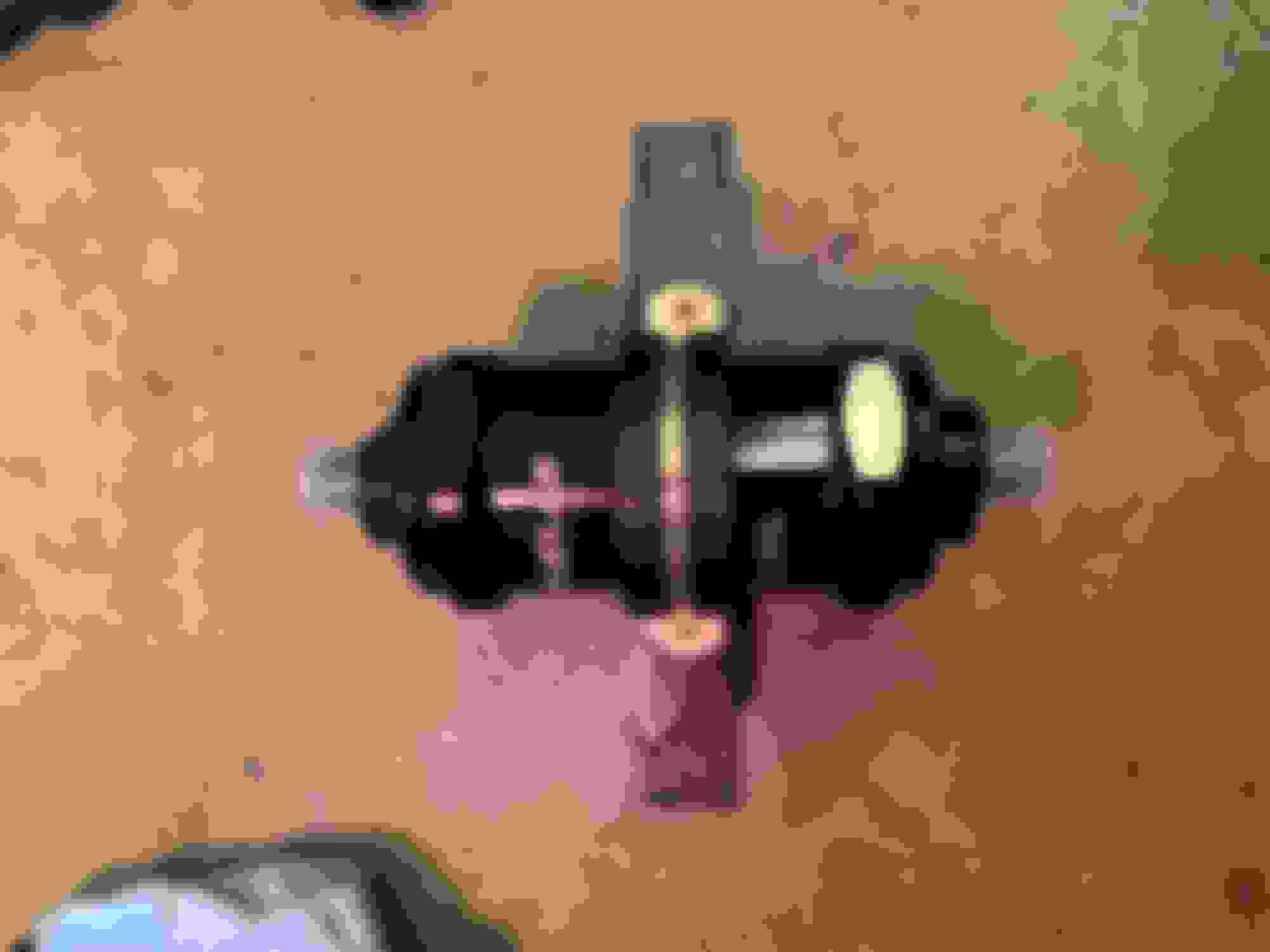
I imagine thats exactly what my shop did too. Looks like One side is the press fit plug and one was tapped (first pic). I'll call to confirm they cleaned the galley or if I'll pull them back out and clean and replace. I imagine the tapped one will just unscrew now, which would make it easy to get out.
Yeah Curly, I had purchased two Mazda press plugs but looks like I won't need them. I just spoke with the shop, they cleaned the galleys and replaced the oil plugs (pictured above). I'm not going to bother to replace the freeze plugs, seems excessive for a car that rarely sees single-digit temps and isn't run with water only.
The pressure on the expansion plugs is determined by the radiator cap and most of us are running higher pressure 20lb caps. They might be fine, but I have seen some in older cores that needed to be replaced. The aftermarket plugs are hit or miss. The made in china plugs were not a good fit and don't use the brass plugs. The oil galley plugs look like they were reused and sealed with RTV. I have done this before without any issues, but its less than ideal. New units sealed with red loctite is preferred. The block was not decked so it might not be necessary to remove the restrictor. I don't believe these are readily available and that is why most shops don't remove them.
Any way to tell if the expansion plugs need replaced visually? My brain is saying I'd rather have the radiator cap blow than the block plugs since the rad cap would be far easier to repair/replace.
The rad caps are spring loaded and can release any excessive pressure without any damage to the cap. It functions this way after most warmups. I would remove one plug for inspection. If it's not excessively rusty, then the rest are most likely ok.
Haven't looked back so may be there - what is the history of this engine - has it been running plain water, or anti-freeze or.other additives that contain corrosion inhibitors? If no/don't know, I'd pull them all, it only takes one to spoil your day.
I am assuming that when opened up or pulled, there was no flood of rusty water ... that would be enough for me to do them all.
Hey Gee, no idea on the history but when I pulled everything off it looked like the inside was in very good condition. The overheating ruined the head and the block was fine, didn't even need decked. After some headaches on the head (crappy ones ordered and refunded) I just got my good one back from being built! I may just do those freeze plugs after all for peace of mind while its out and easy.
Updates:
-Spoke with my machine shop and finally got all the specs and clearances, I'll post those in a couple days when I can get back into the garage.
-They replaced both oil galley plugs after cleaning the galley so we're good there and I'm gonna send it.
-Head is built with spec sheet (can also post that later)
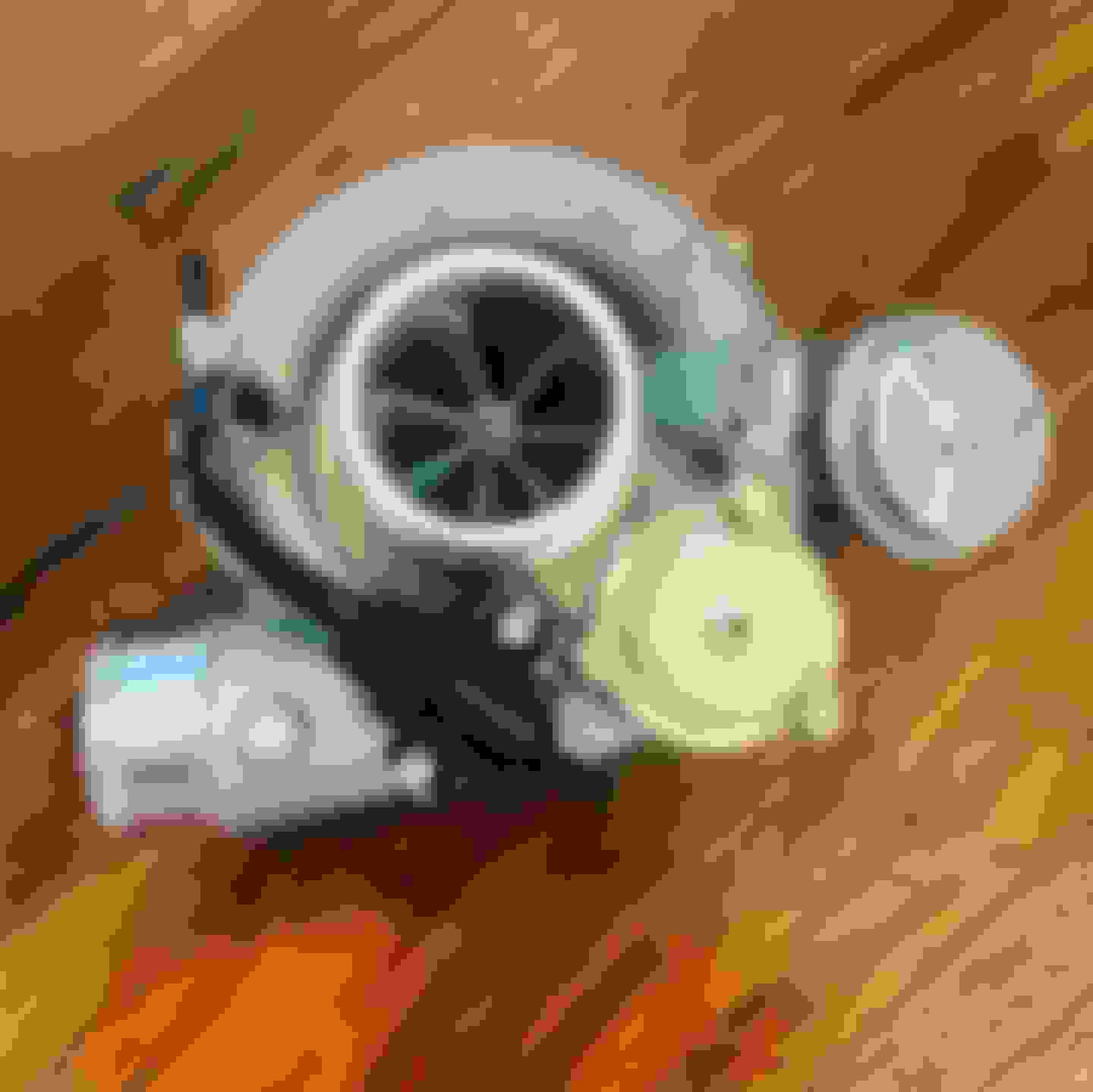
-Turbo arrived
-Fuel Rail and AN fittings for that arrived
To Do this weekend:
-Build a sketchy DIY heat tank to clean the valve cover and then modify it by drilling out the PCV and breather for AN10 fittings to a catch can. Just following what Carpassionchannel did after reading the catch can thread on here.
-Help fix a buddies Tacoma
Random Stuff:
-Sadfab no longer is making their ignition kits. I was looking at the fab9 and FlowForce kits but it seems users here have good write-ups and have had not great experiences with those. So I think I will be going with the kit from DIYAutoTune. I'm not saavy enough to troubleshoot spark issues so I'll just suck it up and get a knwon good kit out the gate. https://www.diyautotune.com/product/...-miata-tuning/
-I still need to look up how to wire up a fuel pump
-Also need to learn how to wire the oil temp and sensors, Mishimoto oil filter sandwich plate is enroute
-Learn about and order flex fuel sensor
I changed out the trans and diff fluid. I'm not sure if the diff had ever been serviced before and its at 140k miles. Yikes.
The EFR6758 snail is here!
The BP6D head is also here! Finished being build with the new I/E valves and springs
So, a couple weeks ago I couldn't get into 1st or 2nd driving home. I made it home on 3rd (thanks short ratios) from stop lights but it was sketchy. I pulled open the turret since the gears sounded fine when they did randomly engage. I found that bolt in the selector was almost falling out it had backed out so far. So I tightened it with red loctite, cleaned up the turret, reesaled it with some Right Stuff rtv and then changed the fluid. And now it feels amazing, absolutely night and day difference from what it was before. Should've done this so much earlier.
a little bonus pic from a cool sunset the other weekend on the test drive with new fluids!
Its been a while since I updated and I have updates, woo!
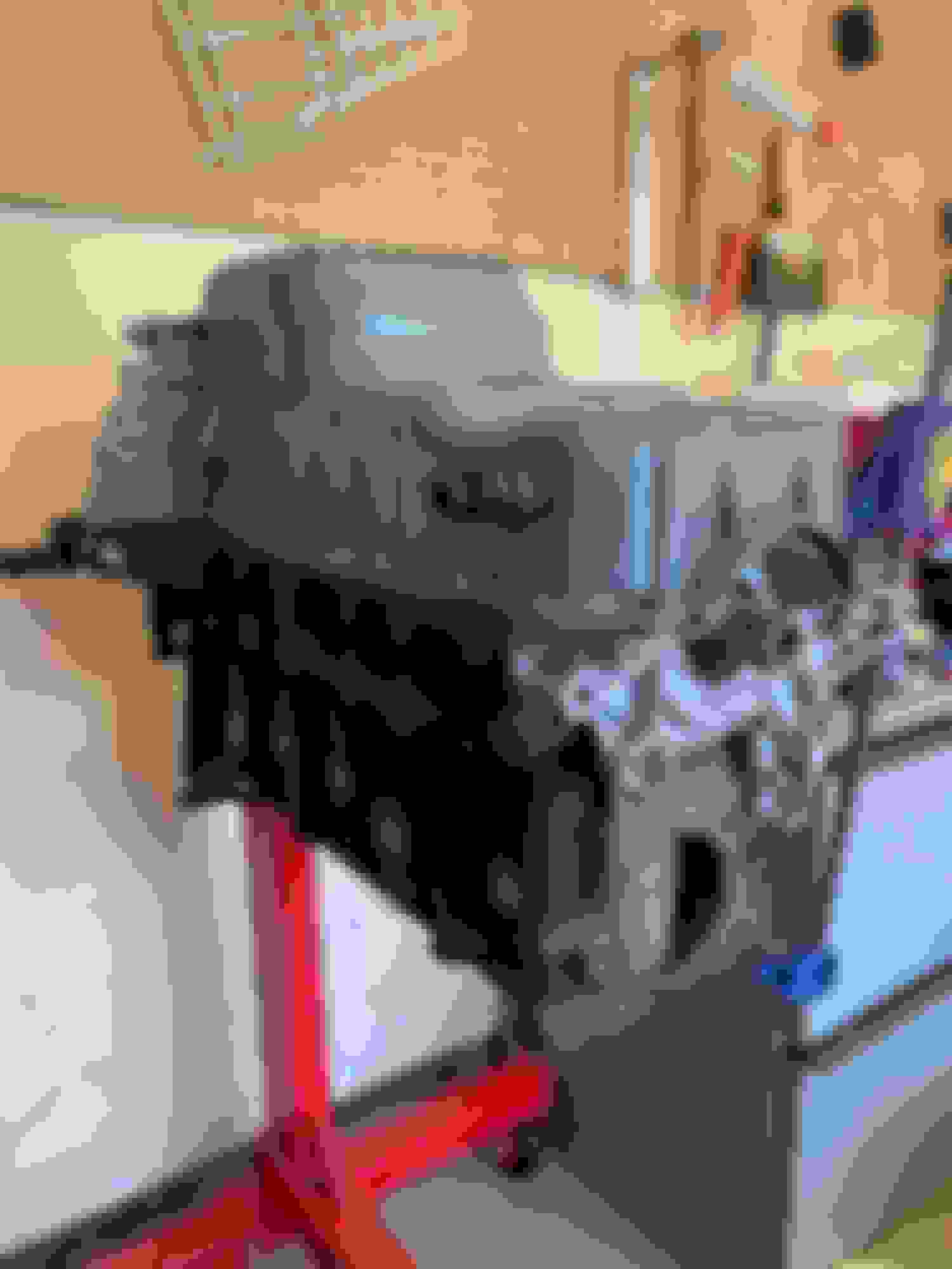
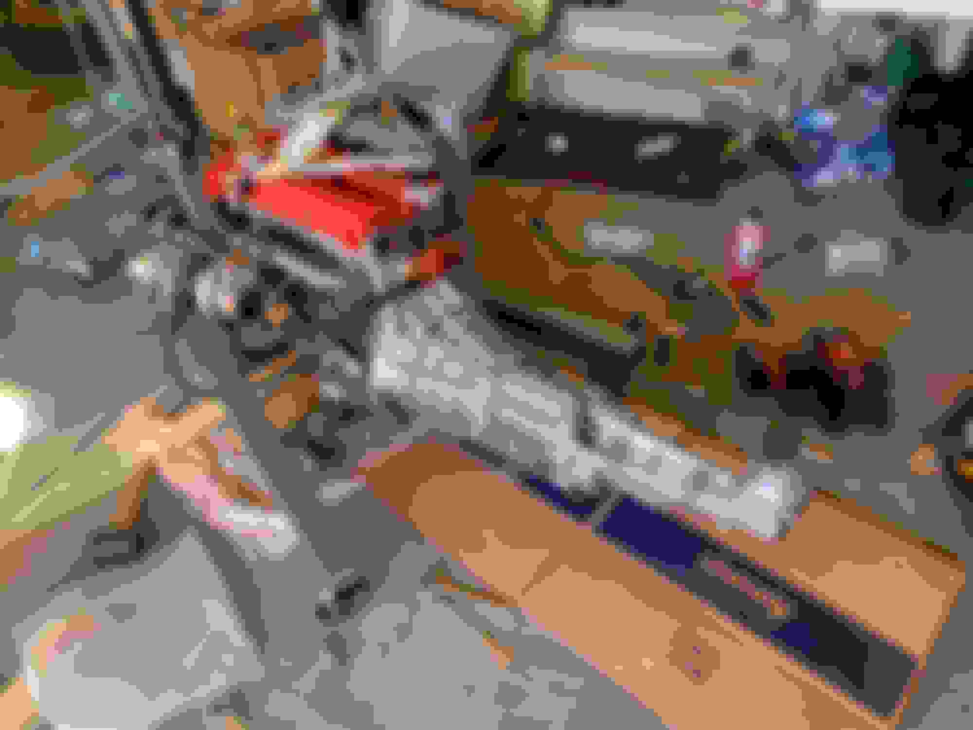
I started assembling the engine. Progress is slow but I'm taking my time and making sure I don't make mistakes. Rotating assembly, then the rods and pistons.
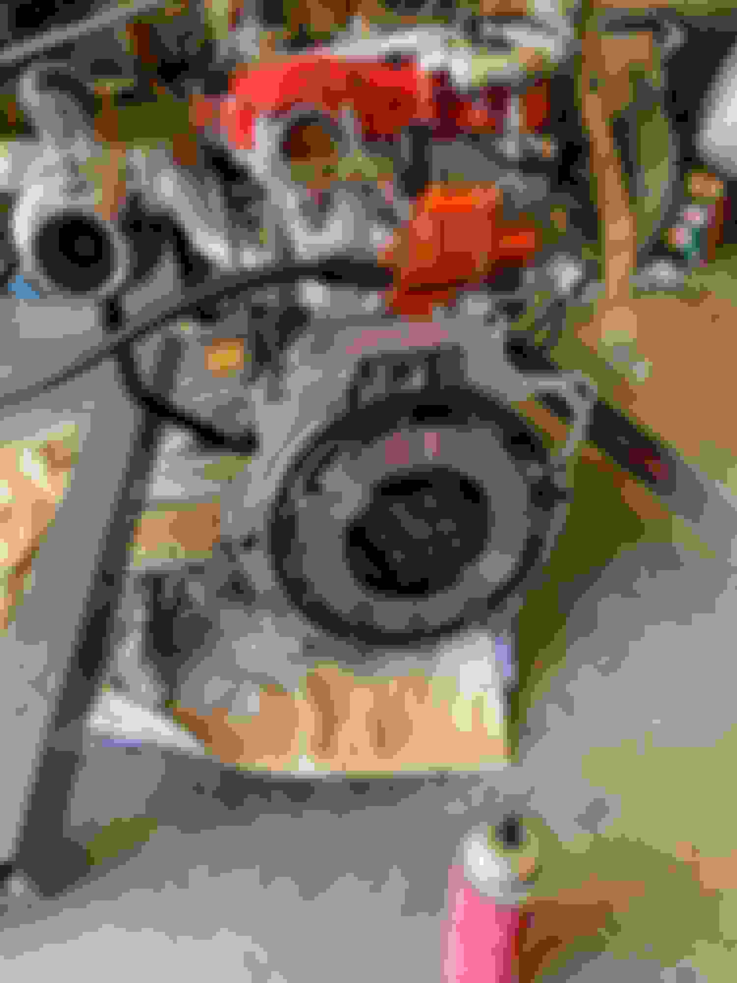
I made my first mistake by sealing the oil pan without putting the MBSP bolts onto the main caps. So I had to pull it off and clean off all the rtv, that was fun.... I also broke an oil pan bolt, hence the wood clamp. So while I cleaned everything, I ordered a new set of oil pan bolts and kept the torque a little lower the second time around.
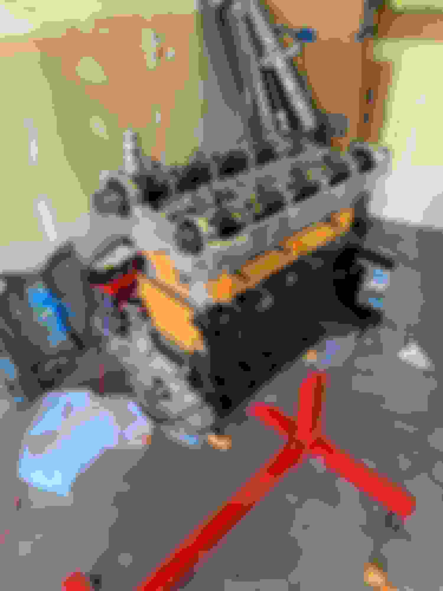
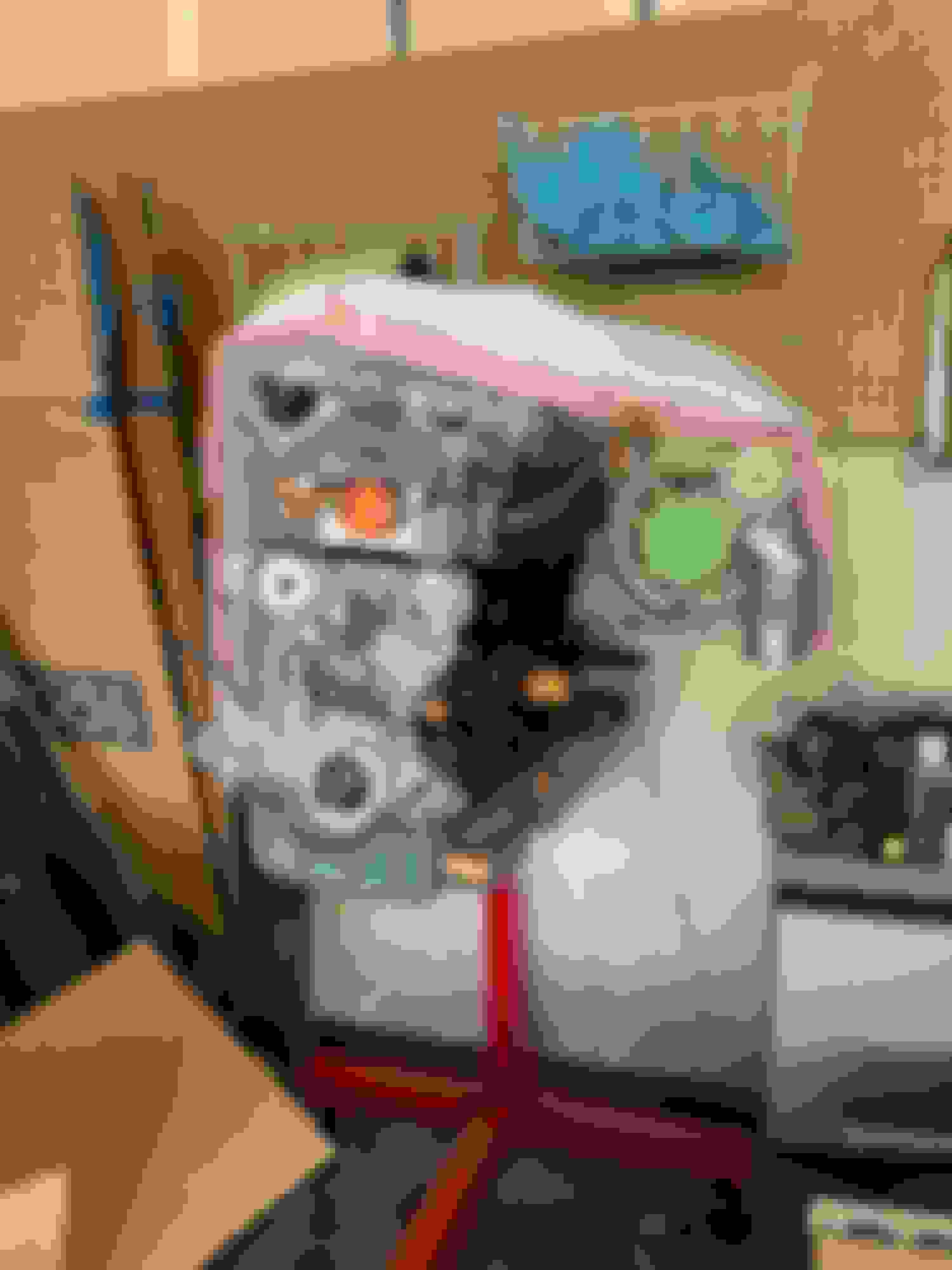
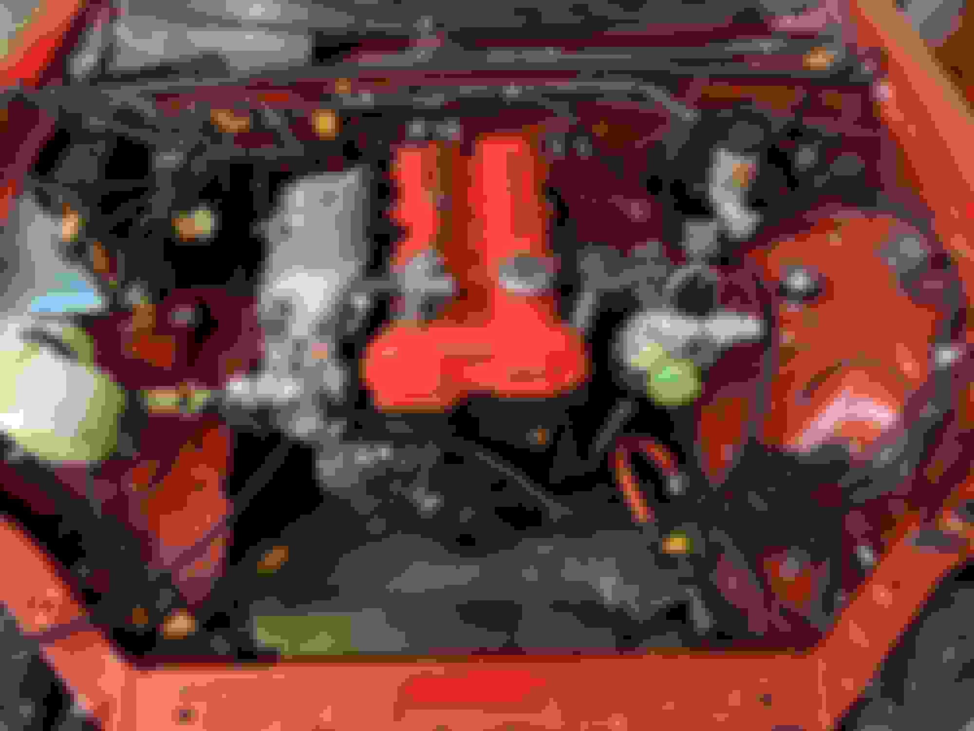
Got the head on and then mocked up the turbo. I had to take it off to clock it differently. Plus my stage 8 iconel studs and locking nuts are on the car's current engine right now so I won't mount it until later. Modified the mixing manifold by pulling out the barb in the front that went to the old thermostat neck (also removed) and put an AN4 fitting in for the water drain. I decided to remove that coolant line and the one going to the throttle body since I won't be driving in icing conditions anyways. Also no pics in this post but I did get the reroute installed on the back, which looks pretty cool.
I had my co-mechanic, Ascari, helping me figure out some things in the engine bay. Going to remove the charcoal filter, EGR stuff and try to figure out what some of these wires and harnesses are for to move them and make room for my intercooler piping.
In the meantime I got a new CX-50! Its pretty cool but has a little too much tech in it for my taste haha.
Next is re-mocking the turbo and getting all of the AN lines fitted for the turbo and the fuel rail. Then its time to pull the motor out of the car so I can steal lots of parts off that motor. I need the crank balancer, intake manifold, injectors, turbo studs/nuts and of course that sick Mazdaspeed oil fill cap.
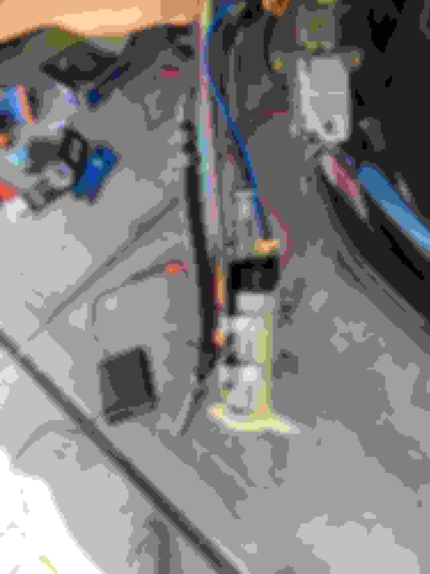
Feeling pretty accomplished, this was my first ever motor pull and I did it all by myself. It went very smooth, only issue was stripped bolt on the downpipe and then figuring out what height to have the car at to give the crane enough room to pull it. I ended up clearing it by 2" after measurements and adjustments to the crane and chains. you can see in the pics I got everything as close together as possible.
All of these inprogress pics of it coming out are overkill, but I am a visual learner and hopefully someone can notice something that helps them in their project if its their first time too.
I also did my first real electrical project, I installed a 240v heater (7500W) so that I don't have an excuse to not get out there even when its cold out
Most of the Air Conditioning stuff is removed, just gotta undo the firewall lines and then remove the guts of the box under the glovebox. Seems doable without removing the dash again.
Other topics of discussion:
1. I caved and bought some ID 1050x injectors, so I have some FlowForce 725ccs that were hardly used for sale!
2. I need to figure out where to relocate the relays to make room for the bigger intercooler piping. Open to suggestions/ideas!
3. I'm a bit confused on my EFR6758 and if I need to hook up the internal diverter valve to anything. My understanding was connecting my 3port MAC, 1 to the IWG, and 1 to the compressor housing, and just leave the diverter venting to atmo, I guess.
4. This being a Mazdaspeed...I think the trans will hold more than the other 6 speeds but I'm not sure how much. Probably gonna grab a getrag 260 locally and prepare for a future trans swap if I blow this one. And use the Kmiata swap kit. Not trilled on losing my speedometer tho :(
Now that the motor is out, its time to clean the trans and start swapping over parts! Being winter here in CO, I spend lots of my days off snowboarding, which is why progress on this is so slow. But I do hope to be on the Dyno with most issues ironed out come early summer.
It is of course a hard wired one, super difficult to find this wattage with 240v plugs. But honestly it was super easy, hardest part was figuring out how to route the conduit through the outside to the inside.
I've had it a couple weeks and turned it on twice so far. Seems like it does a good job. My garage is about 500 sq ft and it got it up from about 35F to 55ish F in 2 hours. Jury is still out on how much its going to cost to run lol, gotta wait for the next electricity bill.
Feeling pretty accomplished, this was my first ever motor pull and I did it all by myself. It went very smooth, only issue was stripped bolt on the downpipe and then figuring out what height to have the car at to give the crane enough room to pull it. I ended up clearing it by 2" after measurements and adjustments to the crane and chains. you can see in the pics I got everything as close together as possible.
Other topics of discussion:
1. I caved and bought some ID 1050x injectors, so I have some FlowForce 725ccs that were hardly used for sale!
2. I need to figure out where to relocate the relays to make room for the bigger intercooler piping. Open to suggestions/ideas! 3. I'm a bit confused on my EFR6758 and if I need to hook up the internal diverter valve to anything. My understanding was connecting my 3port MAC, 1 to the IWG, and 1 to the compressor housing, and just leave the diverter venting to atmo, I guess.
4. This being a Mazdaspeed...I think the trans will hold more than the other 6 speeds but I'm not sure how much. Probably gonna grab a getrag 260 locally and prepare for a future trans swap if I blow this one. And use the Kmiata swap kit. Not trilled on losing my speedometer tho :(
Now that the motor is out, its time to clean the trans and start swapping over parts! Being winter here in CO, I spend lots of my days off snowboarding, which is why progress on this is so slow. But I do hope to be on the Dyno with most issues ironed out come early summer.
THE PORT ON THE CRV (RECIRCULATION) VALVE COVER MUST BE CONNECTED TO A PRESSURE SOURCE. THIS HOSE NIPPLE MUST SEE BOOST PRESSURE WHEN THE ENGINE IS UNDER BOOST, AND MUST SEE VACUUM (OR LACK OF BOOST) IN ORDER FOR THE VALVE TO OPEN. IN OTHER WORDS, CONNECT THE CRV PORT TO THE INTAKE MANIFOLD.
THE PORT ON THE CRV (RECIRCULATION) VALVE COVER MUST BE CONNECTED TO A PRESSURE SOURCE. THIS HOSE NIPPLE MUST SEE BOOST PRESSURE WHEN THE ENGINE IS UNDER BOOST, AND MUST SEE VACUUM (OR LACK OF BOOST) IN ORDER FOR THE VALVE TO OPEN. IN OTHER WORDS, CONNECT THE CRV PORT TO THE INTAKE MANIFOLD.
Wow thank you!!! I read through all of Borg Warner's documentation and didn't find any definitive answer like that.
:
Other topics of discussion:
1. I caved and bought some ID 1050x injectors, so I have some FlowForce 725ccs that were hardly used for sale!
2. I need to figure out where to relocate the relays to make room for the bigger intercooler piping. Open to suggestions/ideas!
3. I'm a bit confused on my EFR6758 and if I need to hook up the internal diverter valve to anything. My understanding was connecting my 3port MAC, 1 to the IWG, and 1 to the compressor housing, and just leave the diverter venting to atmo, I guess.
4. This being a Mazdaspeed...I think the trans will hold more than the other 6 speeds but I'm not sure how much. Probably gonna grab a getrag 260 locally and prepare for a future trans swap if I blow this one. And use the Kmiata swap kit. Not trilled on losing my speedometer tho :(
Now that the motor is out, its time to clean the trans and start swapping over parts! Being winter here in CO, I spend lots of my days off snowboarding, which is why progress on this is so slow. But I do hope to be on the Dyno with most issues ironed out come early summer.
:
1. I did something similar, already had ID1000cc injectors but bought ID1050x injectors since I have to re-tune anyway and "all the cool kids are doing it" so looking at other people's tunes that use them is helpful in determining if mine is screwed up.
2. Mount the relays outside/inside your Cold Air Box, there's enough wire length to do so without cutting them (see pictures below).
4. "This being a Mazdaspeed...", DON'T assume that the gearbox is any better than other NB8B/C 6-speed gearboxes, Mazda did as LITTLE as possible to make a turbo-charged car (they didn't even fit a boost gauge) and with the small amount of additional power it provided, there was NO need to upgrade the gearbox.
DIY Cold Air Box:
I tried to keep my Cold Air Box small. There's enough room in mine to mount 2x relays inside the box but NOT 3.
Not a problem for me since I now only have one BIG-*** fan on my TSE radiator so the 3rd relay isn't needed.
If you still need both fans, make a bigger air box.
FYI:
* Roof bolts on top using 6mm bolts to rivnuts mounted on cold air box side wall
* Hot-side foglight vent used to duct cold air into airbox from underneath, using MSM's shelf OEM intercooler hole
* Turbo intercooler ducting now goes underneath shelf, not across and down through it
1. I did something similar, already had ID1000cc injectors but bought ID1050x injectors since I have to re-tune anyway and "all the cool kids are doing it" so looking at other people's tunes that use them is helpful in determining if mine is screwed up.
2. Mount the relays outside/inside your Cold Air Box, there's enough wire length to do so without cutting them (see pictures below).
4. "This being a Mazdaspeed...", DON'T assume that the gearbox is any better than other NB8B/C 6-speed gearboxes, Mazda did as LITTLE as possible to make a turbo-charged car (they didn't even fit a boost gauge) and with the small amount of additional power it provided, there was NO need to upgrade the gearbox.
2. That a very nice looking box! You're much more skilled than I with fabricating. Thank you for sharing, its a great idea. I'm not sure I can emulate but I'll see what I can come up with.
4. I'm having a hard time finding it now but on the 'speed forums someone did find there was a part difference in the transmissions and that the MS 6-speeds had shot-peened gears. So maybe a tad bit stronger but I'm not going to expect it. Stage 1 is getting this thing running around 250-300whp (babying those 3-4 shifts) and then swapping the trans and maybe even diff/axles down the road.
Been pretty bad about updates on here, but here's whats been going on!
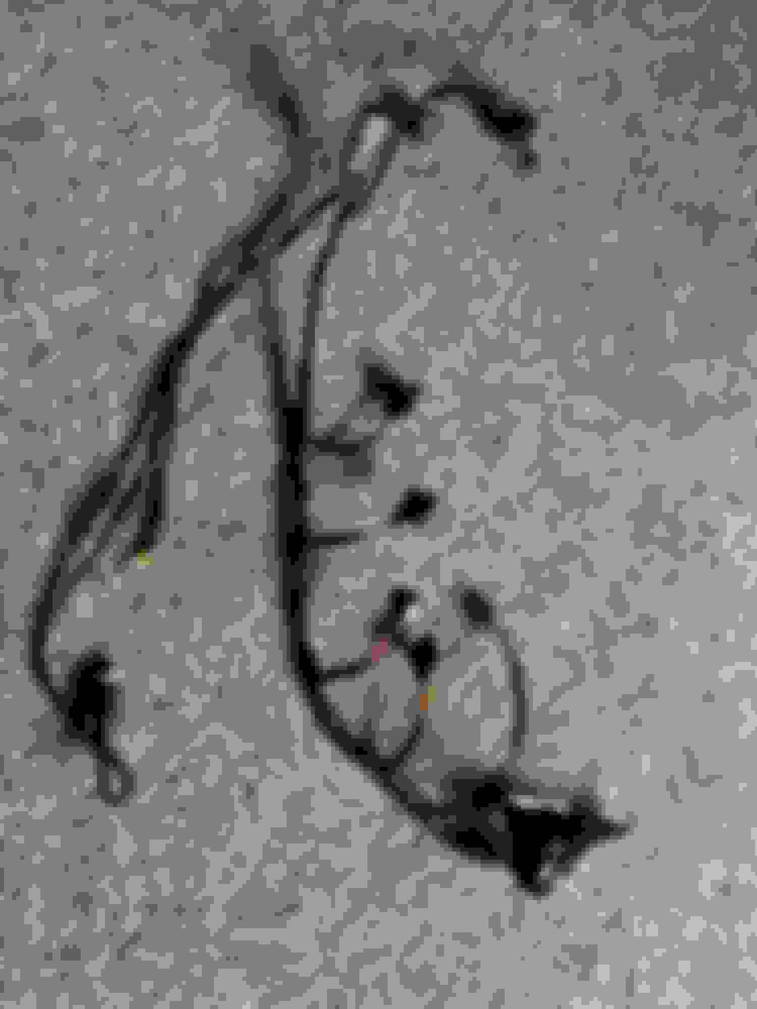
I chopped up the OEM sub-harness for the injectors/CLT and made a new harness for my 1050x's and added the oil temp, pressure and VVT wires. I was pretty nervous to just cut up the factory harness but it worked out quite well. The silver plug is a generic Deustch style connector with the power, ground and signal for the oil pressure sender, the signal wire for the oil temp sensor and the VVT signal wire. I combined the VVT power wire into the same power wire for the injectors since its the same voltage. It was pretty interesting learning experience calibrating the oil sensors. I used an Apple USB block and a crappy old USB charging cable that I cut open and used that to power the pressure sensor. The sensors are generic off Amazon with no voltage or ohms curves so I had to do that myself with my multimeter.
Next on the list was repairing some peeling paint in the engine bay right under the brake booster. I think some brake fluid leaked down there and just ate up the paint since it was basically flaking off. 600 grit sandpaper, a quick soapy wipe down then I sprayed some color matched paint and followed it up with the only clear I found in my garage. It was a high heat ceramic clear, which is why its so shiny. But that should help with the heat repellant and hopefully keeping any spilled fluids off the paint back there. First pic is one I took after cleaning up the grime off the sub frame and steering rack (threw a little black paint on it to cover some bare metal spots), second is after I sanded down the paint then third is how it looks now. Not perfect of course, but so much better in my opinion.
Then was the last big project before I put the new engine in....I think haha. I decided I wanted a return style fuel system given I was going to use an e85 sensor and a fuel pressure regulator so it just made sense. The "return" hard line for the US NB's is slightly smaller, maybe 4/16" than the feed line of 5/16" and I wasn't sure if that diameter would restrict the entire system or not and I wasn't going to do all the fluid dynamics math to figure it out! So I used a 5/16" hardline to AN6 adapter and put them on the two hardlines straight out of the fuel pump. Then I had to find a new spot for the fuel filter, since the stock bracket wasn't seating the aftermarket filter properly. I decided to use aluminum since its easy to manipulate and went to the local hardware store. Found a 3ft long box shaped "tube" and used an angle grinder, a Dremel and some random black paint to get something that I could affix the fuel filter bracket to. Then it was just a matter of running the lines and making the AN fittings for the PTFE hose from Vibrant Performance. Great quality lines, btw. You can see the return line is hooked up to the flex sensor and I purposefully left the feed line long so I can run it directly to the fuel rail, once the engine is back in. Wasn't sure how far it would need to go. Needless to say, I still need to blow out the lines from all the little shavings after I make the last cut.
I tired to do my best to show the filter placement. Note, I am removing ALL of the emissions equipment in the back passenger wheel well area. The fat rubber line is the gas tank vent, I'll just throw some sort of filter on it and call it a day.
Next up is small things like throttle body onto intake manifold, final checks, transmission seals, bolt up the clutch and stuff then its time to drop the engine into the bay!!!
A couple weeks ago, I got the engine in!! Being my first build and swap, I am very excited. My 16 year old self would so proud and happy that I'm finally doing what I've always wanted to do since I knew what a car was!
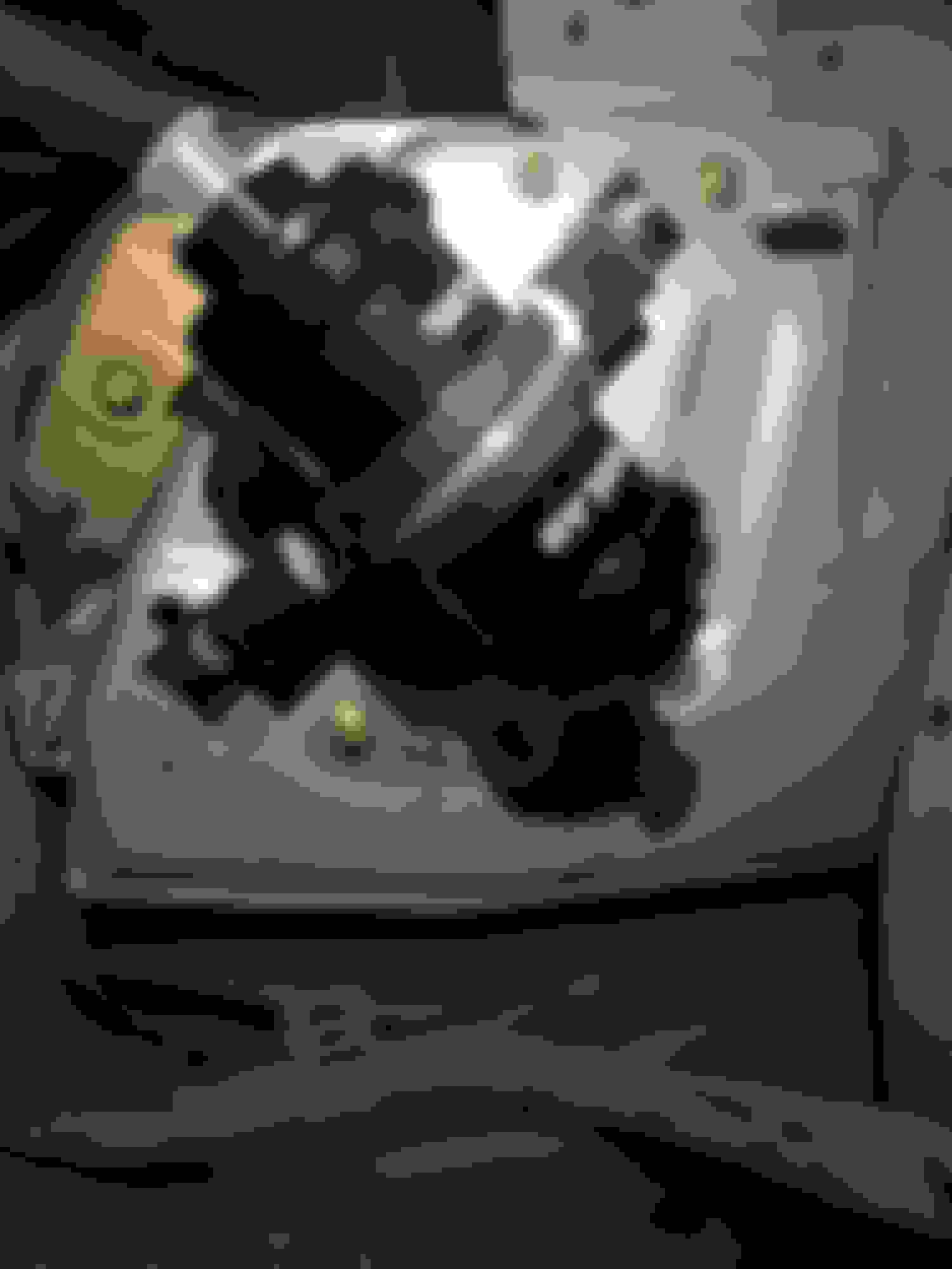
Flyin Miata Happy Meal Kit with the 350hp rated clutch, lightened flywheel. Not pictured is the throw-out bearing or all the work I did to clean out the bell housing from old clutch dust. Had to get creative with some long wrenches to hold the flywheel while I torqued it, sure would be nice to have 3 or even 4 hands sometimes, ha!
With the 6 speed bolted on and a bunch of random miscellaneous things tightened that would've been hard to reach, it was time to throw it in the car. No pics since I was under the car with the trans while my neighbor manned the hoist and guided the top half. Took about an hour with fiddling with the mounts and PPF stuff but we got it!
I also got to work on my DW400 fuel pump. I made lots of mistakes here but I'm not going to hide them since this is all a learning process. For one, you can see some RTV, that is because I initially had the posts too close to the edge and the pump assembly wouldn't seat back on the tank. After much cursing and a break, I moved them but then ran into the issue of not being able to get the bolt through to create the bulkhead connector. I tried both ways but it was contacting the brace/holder for the fuel level assembly. So I got out the dremel and made some room and then threw an extra shrink wrap on there to make sure there was no metal to metal contact. You can also see I cut off the fuel pressure regulator that is in the NB's and then made the return hose just a tad longer to keep the frothing and bubbles down. I still need to do the wiring relay as well.
Now it was time for all of the little custom things to do in the engine bay to get this beast closer to being ready! I'll try to remember them all but if you see anything weird in a picture and have a question, please feel free!
I got some quotes for custom intercooler piping but it was far more expensive than I realized. So I'm gonna do the kit route, I went to silicone intake systems and have the pieces to put this together. Everything is still in progress. but I got the T right before the throttle body to put my BOV at. Initially this was a recirc BOV before i went to a standalone. I threw a filter on there to vent to atmo since its now just running on MAP instead of MAF. From what I read, if you're running MAF, you need to recirc since the ecu is expecting that much air and doesn't expect it to just disappear. Whereas on MAP, the engine doesn't care how much air, just the pressure of it. Plus I love a good blow off noise, sue me .
You can also see on this next pic, I pulled the studs out of the flat top IM and used Skunks bolts since they looked so much nicer and I don't think a nut would've been able to get on the top studs with the shape of the inlet.
I also wasn't keen on the radiator reroute tube contacting my silicone for the TB so I looked around and came up with this solution, I'm very happy with how it turned out and this should help with any theoretical heat soak from the coolant on the air temp. Its a 90 silicone, that I trimmed down to get as close to the rad as possible then a 90 degree aluminum piece from Jegs then just trim the reroute hose to fit.
This part I'm pretty proud of, my first real custom bracket. 3mm aluminum that I heated and bent into a 90 degree and mounted with one bolt that held something else in before. I put a few aluminum washers so it would be flat with the slight raise on the frame rail and then drilled two screws into the frame rail to hold it firmly in place. You can read the gauge easily and this should allow for very easy access and to check/diagnose anything regarding fuel pressure. The fuel return line is coming off the back of the radium rail parallel to the coolant reroute hose and the dropping down the bottom with a 90 degree fitting to the flex sensor mounted on the side of the passenger frame rail as previously shown.
The catch can isn't mounted yet but I'm trying to devise a way to put it there since I'm kind of out of any other option at this point, its just too tall to mount straight up and down. I can't put it in the back on the firewall like most people since I have so much back there already.
You may also notice I got some aluminum rad mounts, the fit is perfect and any weight saving sis good in my book.
Now those eagle eyed viewers might have already noticed I have a LOT of room on the passenger side of the radiator. I decided to cut out one of the rad fans. I know its probably not the best idea but I have lots of cooling mods planned for the future and I don't plan on hardcore tracking. I also needed the room where the OEM coolant resevoir sat for my catch can. So I found this syle of resevoir and made a little bracket and bolted it to my radiator. It was off amazon, if you want the link let me know. I will need to run a rubber hose to the bottom where it fills up. Technically its below the radiator so I am a bit concerned this will even work from a physics standpoint but I'm just gonna have to send er bud.
Next up was getting the wiring sorted. Since I removed AC, I have the two holes on the passenger side firewall and chose to run all my wires through there after a failed attempt on the driver side firewall. The wire include my oil pressure, oil temp, VVT, flex fuel sensor, additional sequential spark wires from the diyautotune max spark kit and then power/grounds. I also wrapped a ton of random wires in the heat protectant looming since my wires are getting pretty beat up.
So this is how she is sitting today, literally lol. Lots of stuff in progress or unfinished. I still need to crimp on the connectors and route my wiring under the dash and pin into megasquirt. I need to do the intercooler piping, spark kit, the exhaust, the turbo blanket, heat wrap, heat shield, fuel pump relay and catch can. Theres probably more but thats just what I can remember right now. Been making a ton of progress and cannot wait!
If anyone has questions, suggestions, comments, I would love them! If you read all of this post, you must really enjoy Miatas or watching noobs make mistakes haha, happy Sunday!!!
Oh, I also just realized two things, number 1 the radiator coolant hose is bent weird in the last pic since I was tightening the fuel lines and needed it out of the way, it won't sit like that normally.
And two, my power steering line is literally touching the compressor housing and I never noticed. Any ideas on that? I'll try to bend it but it would be nice to just change out or turn it around if possible.


 0
0


 . I also broke an oil pan bolt, hence the wood clamp. So while I cleaned everything, I ordered a new set of oil pan bolts and kept the torque a little lower the second time around.


 .
.