DIY Port and Polish
 09-22-2008, 09:33 AM
#1
Junior Member
Thread Starter

Join Date: Aug 2005
Location: Iowa
Posts: 338
Total Cats: 0
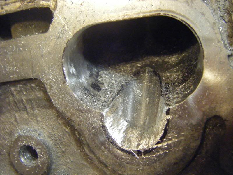
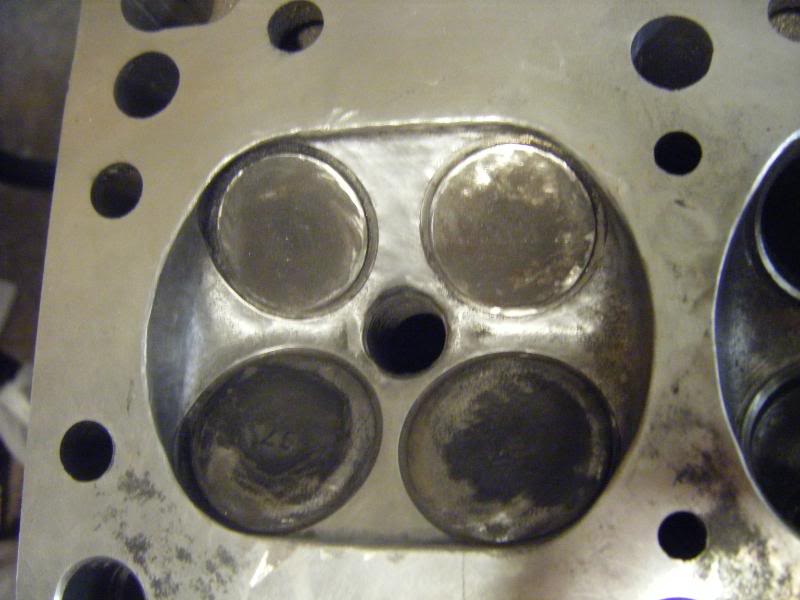
i put the gasket on the intake side of the cylinder head and
outlined the inside part with a sharpie marker to use as a reference point.
I then used my dremmel with several tips to get this ported...
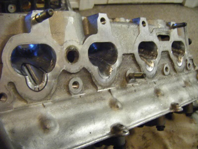
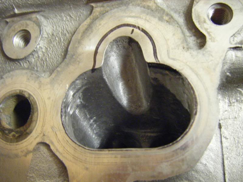
here's a different picture...
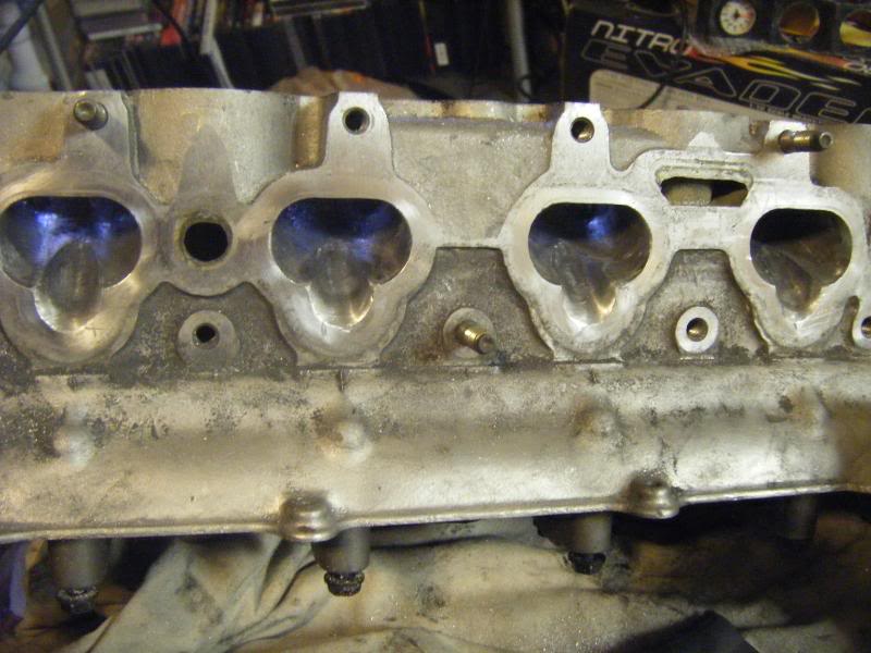
a mild polish...
and the final pic before i take it back to the machine shop today...
outlined the inside part with a sharpie marker to use as a reference point.
I then used my dremmel with several tips to get this ported...
here's a different picture...
a mild polish...
and the final pic before i take it back to the machine shop today...

Reply
 0
0

0

 09-22-2008, 10:05 AM
#3
Meh, I wouldn't have done it like that. Your efforts could have been better spend doing other things. The "port matching" you did is not necessarily an improvement and could actually make it worse. Better, you would have spent your time ushrouding the combustion chambers and blending the combustion chambers into the seats and the seats into the throat. You need to get a book on cylinder head modifications.
Reply
0
0


 09-22-2008, 01:58 PM
#6
Junior Member
Thread Starter
Join Date: Aug 2005
Location: Iowa
Posts: 338
Total Cats: 0
the old valves were in place as i was sanding, i have the FM valves going
in so i'm not too worried about scratching the old ones...
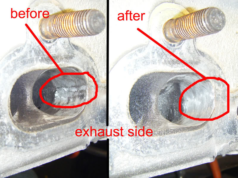
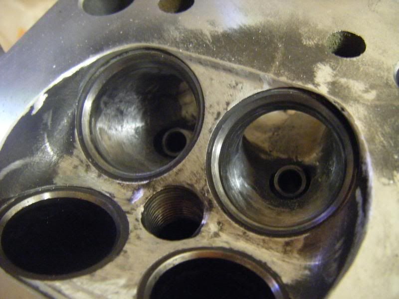
yeah thats one thing i worked on alot
but there were also alot of rough areas that needed to be smoothed
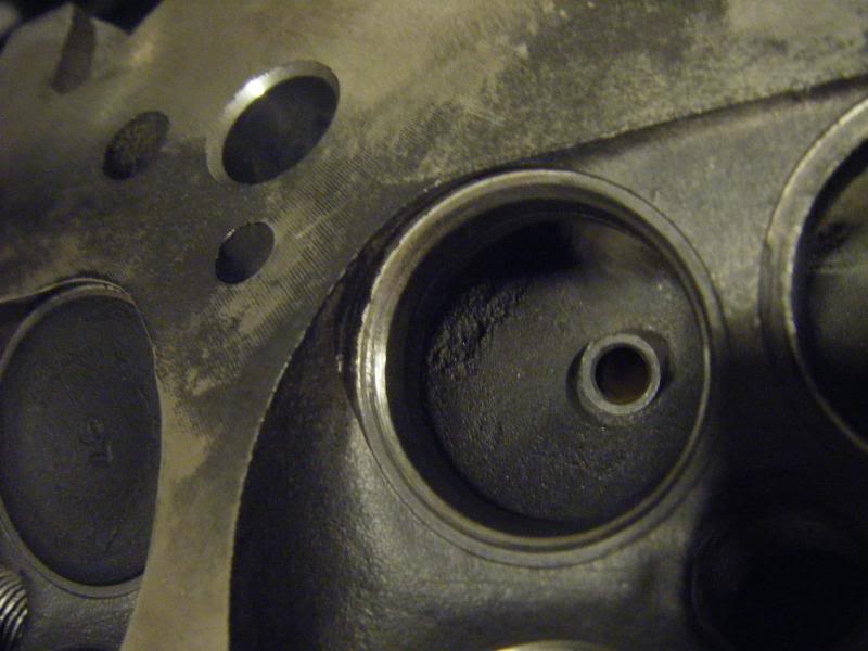
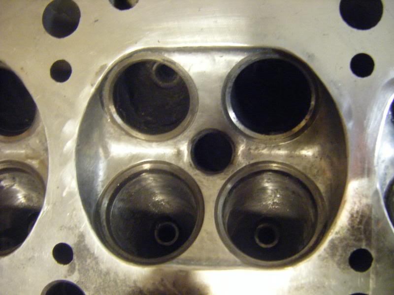
and here is the valve seats for the new FM valves
in so i'm not too worried about scratching the old ones...
but there were also alot of rough areas that needed to be smoothed
Reply
0
0


 09-23-2008, 09:22 AM
#12
Junior Member

Join Date: Aug 2007
Posts: 115
Total Cats: 0
I did this exact same thing this weekend to my head while my engine is apart. I used a die grinder and some sandpaper cartridge rolls. Seem to work well for me. I cleaned up the casting marks mainly, didn't really enlarge the passages or ports. Then I went back over it with some polishing compound.
They look real good, but we'll see how they perform when I get the engine back together.
Also BTW reassembling the valve train sucks. Once you get the hang of getting the retainers to seat on the valve its not to bad though. Grease is your friend.
They look real good, but we'll see how they perform when I get the engine back together.
Also BTW reassembling the valve train sucks. Once you get the hang of getting the retainers to seat on the valve its not to bad though. Grease is your friend.
Reply
0
0
09-23-2008, 11:26 PM
#13
Junior Member
Join Date: Aug 2007
Posts: 115
Total Cats: 0
I don't have a factory service manual, but I need some torque specs for the head. Could someone enlighten me as to what I should torque the camshaft cap bolts to? I'm thinking that since its going into aluminum the torques should be similar to that of the spark plugs???
Also could someone tell me the torque pattern for the head bolts. I've searched the forums and the intarwebs and have not come up with good answers to these questions.
Also could someone tell me the torque pattern for the head bolts. I've searched the forums and the intarwebs and have not come up with good answers to these questions.
Reply
0
0
09-23-2008, 11:36 PM
#14
I don't have a factory service manual, but I need some torque specs for the head. Could someone enlighten me as to what I should torque the camshaft cap bolts to? I'm thinking that since its going into aluminum the torques should be similar to that of the spark plugs???
Also could someone tell me the torque pattern for the head bolts. I've searched the forums and the intarwebs and have not come up with good answers to these questions.
Also could someone tell me the torque pattern for the head bolts. I've searched the forums and the intarwebs and have not come up with good answers to these questions.
Reply
0
0

Thread
Thread Starter
Forum
Replies
Last Post
Zaphod
MEGAsquirt
47
10-26-2018 11:00 PM
stoves
Suspension, Brakes, Drivetrain
5
04-21-2016 03:00 PM


