Another Electronic Det Can Example
 01-23-2012, 09:53 AM
#22
Elite Member
Thread Starter
iTrader: (4)

Join Date: Mar 2008
Location: Granbury, TX
Posts: 6,301
Total Cats: 696
I think so. Can't think of a downside to J.B. Weld. It is also much more solid, so it should transfer vibration better.
I'm about to build another set of these using a battery lug for permanent attachment to the block. I drive around with the battery clamp version, but I always worry that it might come off the car -- it's probably better suited for dyno use and use as an electronic stethoscope. I think I'll use J.B. Weld on the next set. Will let everyone know how it works. I would expect that a battery lug version with J.B. Weld would yield even better audio.
I'm about to build another set of these using a battery lug for permanent attachment to the block. I drive around with the battery clamp version, but I always worry that it might come off the car -- it's probably better suited for dyno use and use as an electronic stethoscope. I think I'll use J.B. Weld on the next set. Will let everyone know how it works. I would expect that a battery lug version with J.B. Weld would yield even better audio.

Reply
 0
0

0
02-19-2012, 02:05 PM
#23
Junior Member

Join Date: Nov 2009
Location: Dumfries, VA
Posts: 109
Total Cats: 2
I've found the following to make things a bit easier when using this setup:
1. Enable sound during recording in Audacity by going to Transport - > Software Playthrough. Make sure there is a check mark on the left.
2. A really good example of what to expect with knock:
1. Enable sound during recording in Audacity by going to Transport - > Software Playthrough. Make sure there is a check mark on the left.
2. A really good example of what to expect with knock:
Reply
2
2
03-04-2012, 05:14 PM
#24
Elite Member
Thread Starter
iTrader: (4)
Join Date: Mar 2008
Location: Granbury, TX
Posts: 6,301
Total Cats: 696
So, I've been using my battery clip det cans for tuning, and they work well. However, there's always a risk that something could come off the car at high speed with these. It's probably just a mental risk (it hasn't ever happened), but I'm still paranoid.
Early in the thread, Curly suggested that rigging this up with some kind of eyebolt setup for permanent installation would work well. Then MD323 suggested a copper lug. Both suggestions sounded good to me, so this is what I built today:
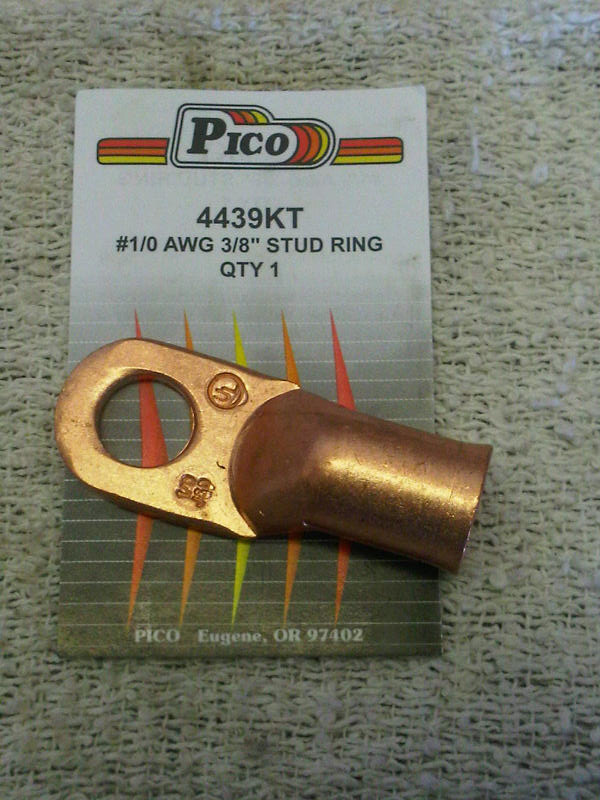
All of the materials are the same as before with the exception that I'm using a #1/0 AWG 3/8" Copper stud ring:
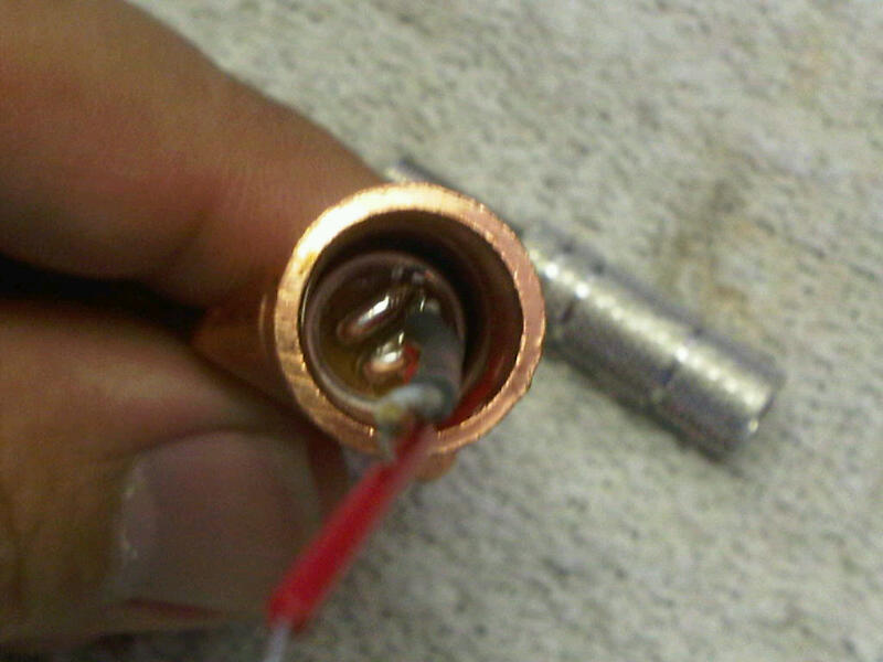
The microphone element fits perfectly into the lug. Get it in all the way and secure it with JB Weld, high-temp RTV or similar (see post #31):
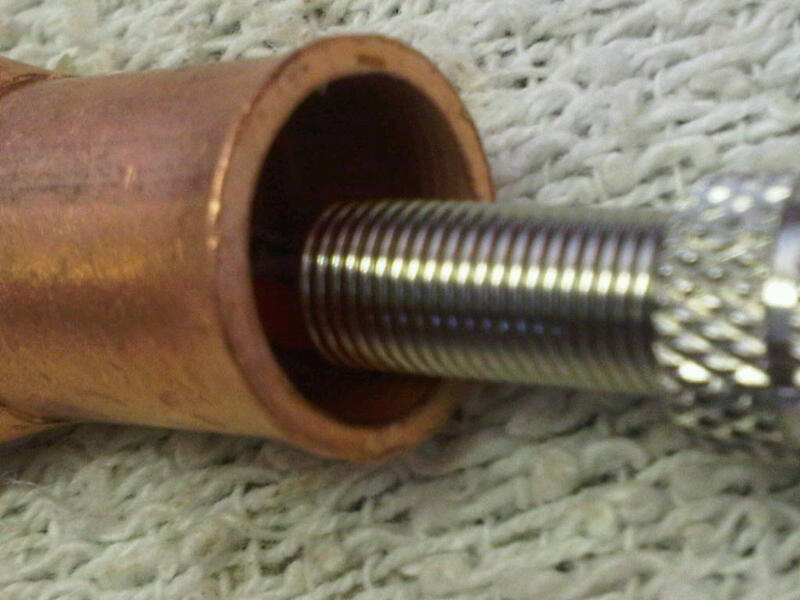
Put the plug shields over the microphone wire. You want it to be inside the lug just a bit as we're going to crimp the lug over the shield:
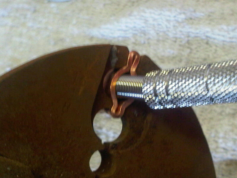
Crimping away. Crimp enough, but not too much. The wires running within the shield are delicate.The crimp also secures the microphone element within the lug This theory didn't stand the test of time -- make sure the microphone element has been secured within the lug with JB Weld, high-temp RTV or similar -- see post #31:
Finished assembly with heat shrink tubing making things weather and dirt-proof(I didn't use any other type of sealant or epoxy):

So, now I have two det can microphones -- one I can move around to troubleshoot car noises, and the other will be permanently mounted for tuning duty:

3/8" hole works perfectly with the 14mm engine mount bolt:
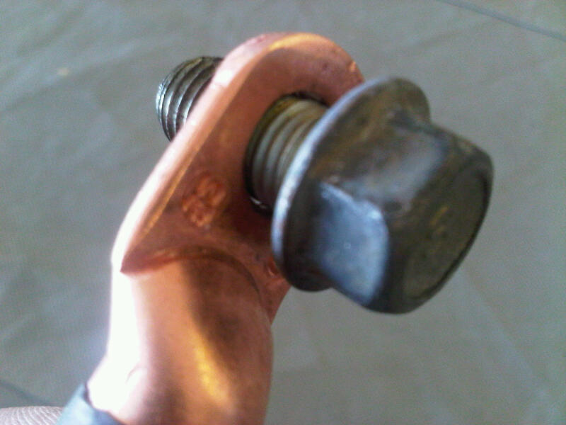
Here's the assembly in its new permanent home:

Really happy with this. The sound quality from the clip-on det can microphone was pretty good, but this is WAY better. I wasn't expecting a sound quality improvement -- but I'll take it.
YMMV.
Early in the thread, Curly suggested that rigging this up with some kind of eyebolt setup for permanent installation would work well. Then MD323 suggested a copper lug. Both suggestions sounded good to me, so this is what I built today:
All of the materials are the same as before with the exception that I'm using a #1/0 AWG 3/8" Copper stud ring:
The microphone element fits perfectly into the lug. Get it in all the way and secure it with JB Weld, high-temp RTV or similar (see post #31):
Put the plug shields over the microphone wire. You want it to be inside the lug just a bit as we're going to crimp the lug over the shield:
Crimping away. Crimp enough, but not too much. The wires running within the shield are delicate.
Finished assembly with heat shrink tubing making things weather and dirt-proof
So, now I have two det can microphones -- one I can move around to troubleshoot car noises, and the other will be permanently mounted for tuning duty:
3/8" hole works perfectly with the 14mm engine mount bolt:
Here's the assembly in its new permanent home:
Really happy with this. The sound quality from the clip-on det can microphone was pretty good, but this is WAY better. I wasn't expecting a sound quality improvement -- but I'll take it.
YMMV.
Last edited by hornetball; 03-09-2012 at 08:53 AM.
Reply
1
1
03-06-2012, 07:21 PM
#25
Junior Member
Join Date: Nov 2009
Location: Dumfries, VA
Posts: 109
Total Cats: 2
That looks pretty good. Wondering if you get any better results with the copper lug? You didn't say either way, so I imagine not. I get really nasty high frequency noise and I used all of the exact same materials from the original setup. Anyone else have this problem or any recommended fixes? Is there a way to suppress noise with Audacity realtime? I played around with it for a while and found nothing for realtime noise filtering. Any help would be appreciated.
Reply
0
0
03-06-2012, 07:35 PM
#26
Elite Member
Thread Starter
iTrader: (4)
Join Date: Mar 2008
Location: Granbury, TX
Posts: 6,301
Total Cats: 696
Yes, the sound from the copper lug is better.
High frequency noise is usually related to electronic interference. Your alternator is an especially effective generator of this type of noise (as are your coils, injectors, etc.). Make sure that the cable you use between the det can microphone and your computer is a high-quality shielded type, and try to route away from the alternator. The use of a shielded plug and good electrical contact between the plug shield and engine ground is really important.
High frequency noise is usually related to electronic interference. Your alternator is an especially effective generator of this type of noise (as are your coils, injectors, etc.). Make sure that the cable you use between the det can microphone and your computer is a high-quality shielded type, and try to route away from the alternator. The use of a shielded plug and good electrical contact between the plug shield and engine ground is really important.
Reply
0
0
03-06-2012, 10:42 PM
#27
Elite Member
Thread Starter
iTrader: (4)
Join Date: Mar 2008
Location: Granbury, TX
Posts: 6,301
Total Cats: 696
Drove home with the det can. I'm definitely picking up alternator whine like sccaax mentioned. The whine is in the shield, not in the signal, which means I can turn the volume up and have a decent S/N (probably why I never really noticed it before). I think if there was a way to ground the shield at the computer end it would help.
Reply
0
0
03-07-2012, 08:22 AM
#29
Newb

Join Date: Jun 2011
Location: So. MD
Posts: 2
Total Cats: 0
I'm working on rigging up an electronic Stand-Alone type today. If all goes well I'll be finished before work but hopefully I'll have pictures up between this afternoon and Monday. This should be perfect to monitor my 1.6 pre and post-turbo, and should work better for me since I feel more comfortable listening actively through headphones rather than through my computer or a recording. This has been a very inspiring thread so far (I hate working on electronics/wiring yet I'm doing this anyway)
Reply
0
0
03-07-2012, 08:24 AM
#30
Elite Member
Thread Starter
iTrader: (4)
Join Date: Mar 2008
Location: Granbury, TX
Posts: 6,301
Total Cats: 696
I'm going by the Shack today to pick up some Ferrite Clamps and see if I can cut down on the alternator whine in the cable shield. Will let you know if that works. Any EE's out there have any advice for the alternator whine?
Reply
0
0
03-09-2012, 02:14 AM
#31
Elite Member
Thread Starter
iTrader: (4)
Join Date: Mar 2008
Location: Granbury, TX
Posts: 6,301
Total Cats: 696
Fail #1, Alternator and Ignition Noise:
Scaax has this bad. I definitely had some too. Investigating, I tried the following:
1. Ferrite clamps: Made no difference at all.
2. Plugging the laptop into the cigarette lighter to give it a ground. Made things a LOT worse. I think I actually set up a ground loop that exacerbated the noise.
3. Ditched the Radio Shack "shielded" cable and fabbed my own. WIN -- no noise whatsoever -- problem solved.
Let's look at why #3 fixed the problem. The Radio Shack cable is two conductors with a shield. The shield acts like an antenna and picks up RF energy from the environment (mainly the alternator). The shield also doubles as the ground wire for the microphone assembly and is terminated at both ends (i.e., that alternator noise goes directly into your computer audio card ground plane). What we need to do is route the alternator whine into the engine block and keep it away from the computer audio card.
To accomplish this, I sourced cable that had three conductors and a shield. The three conductors are terminated to a 1/8" stereo jack (Radio Shack P/N 274-274) on the engine block end and a 1/8" stereo plug (same as the plug used for the microphone assembly) on the computer end. The shield is joined to the ground conductor ONLY ON THE ENGINE BLOCK END. DO NOT TERMINATE THE SHIELD ON THE COMPUTER END. I had some really high-quality aircraft signal cable laying around and used it to build my new cable. This cable had three twisted conductors, a full-length braided shield and Tefzel covering. Overkill, but it worked great.
So, to summarize, build your own cable, terminate the shield of your cable ONLY AT THE ENGINE END, and make sure you don't power your computer from the car's electrical system (have it run off of its internal battery). Do this, and you will not hear unwanted noise.
Fail #2:
I'm pretty sure my microphone is loose and rattling a tiny bit inside the copper lug. I get some noise that sounds like static or an overdriven speaker when I sit in the garage and rev the engine. This wasn't happening when I first built the lug microphone, but it has developed over the last few days as I've driven the car. Unfortunately, the noise sounds a bit like det, so it is definitely something that needs to be addressed. I'm wishing I had secured the microphone with JB Weld or high-temp RTV. Looks like I get to build another lug microphone . . . practice makes perfect?
Reply
1
1
03-09-2012, 07:24 PM
#32
Junior Member
Join Date: Nov 2009
Location: Dumfries, VA
Posts: 109
Total Cats: 2
I had my suspicions about that cable when I bought it. But I guess it breaks down to how it's used. Would this work? - Get another male plug and a female plug and solder the first two rings together for the plugs on the computer end leaving the shield unconnected at the computer. That way, I can reuse the cable I've got and its a bit cheaper as well.
I would recommend Gorilla glue as a higher temperature long-term solution. Working really well for my battery clamp so far. It bubbled like crazy. Someone recommended baking the air out, but I didn't want to risk damaging the mic. I don't see a problem with the bubbles. Heck, they're a great insulator and nobody ever sees it anyways. I do like the copper lug idea.
I would recommend Gorilla glue as a higher temperature long-term solution. Working really well for my battery clamp so far. It bubbled like crazy. Someone recommended baking the air out, but I didn't want to risk damaging the mic. I don't see a problem with the bubbles. Heck, they're a great insulator and nobody ever sees it anyways. I do like the copper lug idea.
Reply
0
0
03-09-2012, 07:39 PM
#33
Elite Member
Thread Starter
iTrader: (4)
Join Date: Mar 2008
Location: Granbury, TX
Posts: 6,301
Total Cats: 696
I don't think that will work because you still need a ground wire to interconnect the ground plane of the computer's sound card and the (-) end of the microphone.
Here's a link with some info:
http://www.hobby-hour.com/electronic...microphone.php
Building a cable isn't much more money than you're talking about anyways. All I did was get a length of 3 conductor shielded cable, a male plug and a female jack.
Also, if you're still using the battery clamp version, take a look at how I connected it in the original write-up. You'll notice the cable's initial routing was down and away from the alternator. There is less noise if you do it that way and try to use engine structure to block the alternator. Better cable is the right solution though.
Reply
0
0
03-10-2012, 04:23 PM
#34
Elite Member

iTrader: (2)
Join Date: May 2008
Location: Portland, Oregon
Posts: 3,468
Total Cats: 365
More good info. Thanks guys. Do you just run the cable into the cabin through an open window?
Edit: Just ordered some of that cable from Aircraft Spruce since it's not terribly expensive.
Edit: Just ordered some of that cable from Aircraft Spruce since it's not terribly expensive.
Last edited by Mobius; 03-10-2012 at 04:40 PM.
Reply
0
0
03-10-2012, 07:13 PM
#35
Junior Member
Join Date: Nov 2009
Location: Dumfries, VA
Posts: 109
Total Cats: 2
You can actually run it over the seal between the firewall and hood and just under the quarter panel and through the door near the hinge. That's what I'm doing for a temp setup. A few less looks from the bacon.
Reply
0
0
03-10-2012, 07:18 PM
#36
Junior Member
Join Date: Nov 2009
Location: Dumfries, VA
Posts: 109
Total Cats: 2
Hornet, I thought I understood what you were doing but now I'm more confused. The - from the mic goes to #3, then how are you talking about grounding the shield any differently? Can you sketch up something quick in paint? The link doesn't help about the shield bit. Is the shield essentially another path on the wire? How does it interface physically on the connector(s)?
Reply
0
0
03-10-2012, 07:47 PM
#37
Junior Member
Join Date: Nov 2009
Location: Dumfries, VA
Posts: 109
Total Cats: 2
Ah, I think I get it now: The radioshack shielded cable is really 2 conductor and the shield and neg are both carried on the jacket and at Pin 3 on both ends. With that said, couldn't you just make sure the neg/ground doesn't touch the lug or battery clamp and rely on the neg on the audio card end? I would think that this gets rid of any possibility of completing the loop by taking the same ground as the alternator and any other non-solid-state component out of the mix. Provided the ground at the PC isn't too noisy? This is an ME talking not EE. Help me out.
Reply
0
0
03-11-2012, 01:41 AM
#38
Elite Member
Thread Starter
iTrader: (4)
Join Date: Mar 2008
Location: Granbury, TX
Posts: 6,301
Total Cats: 696
Ah, I think I get it now: The radioshack shielded cable is really 2 conductor and the shield and neg are both carried on the jacket and at Pin 3 on both ends. With that said, couldn't you just make sure the neg/ground doesn't touch the lug or battery clamp and rely on the neg on the audio card end? I would think that this gets rid of any possibility of completing the loop by taking the same ground as the alternator and any other non-solid-state component out of the mix. Provided the ground at the PC isn't too noisy? This is an ME talking not EE. Help me out.
The RF from the alternator is powerful and has to go somewhere. It's not a ground loop issue. You've got to give that energy an outlet, and the proper outlet is into your engine block. If you let it into your computer, you'll hear it. You'll notice that the alternator noise is constant -- it doesn't change volume with the slider. In fact, you can move your slider all the way to the minimum position, and the alternator whine will still be loud and clear. That's a dead giveaway.
So, to summarize:
Three conductors and a shield, let's call them:
1. MIC+
2. MIC-
3. MIC Bias (3-5VDC from your sound card)
4. Shield.
On the jack at the det can end, wire as follows:
1. MIC+ to tip.
2. MIC- to base.
3. MIC Bias to ring.
4. Shield to base.
On the plug at the computer end, wire as follows:
1. MIC+ to tip.
2. MIC- to base.
3. MIC Bias to ring.
4. Shield is NOT terminated.
While it is true that at the jack, Shield and MIC- are wired together, the alternator whine will seek the easy exit through the engine block rather than follow a smallish 22-gauge wire for several feet into your computer. That's why this works.
Profit.
Reply
2
2
06-21-2012, 11:53 PM
#39

Just built one of these. Thank you hornetball for the awesome write-up. I potted mine in JB weld and used all the parts mentioned in this thread except for the 3/8 lug, since the mic element wouldn't fit in the lug I bought at walmart. Since I was working on this at midnight and I was desperate to get it done, I found out that the EGR pipe from a 95 motor is the perfect inner diameter for the mic element lol. Crushed one end flat and drilled a 10mm hole in it, and will be bolting it up to the stock knock sensor location on my 2001 block.
Note to anyone else doing this... I wasn't thinking the first time around, and forgot that a microphone works because of a moving diaphragm. I just had in my mind that fully surrounding it with JB weld would give it rigid contact at all points, allowing it to pick up more sound. If you fully surround the mic element with JB weld, though, you can potentially limit the movement of the diaphragm and get really shitty results. This happened on my first attempt. Thankfully I tested the wired-up mic element before potting it, otherwise I wouldn't have realized how much the noise level decreased after potting.
For the first one, I put some JB weld in the tube, inserted the mic, and then filled it up the rest of the way with JB. It worked, but the sound was ---- compared to before potting. For the second one, I just inserted the mic element into the empty tube, gave it a light press with a dental tool to be sure it was at the bottom of the hole, and then filled the rest of the tube with JB weld, leaving the front face of the mic element exposed. I've just bench tested it so far, but sound is MUCH better on the second version. At least as good as the bare mic element, if not better. Bolting it up to the motor tonight, hopefully doing some tuning this weekend.
Reply
2
2
06-27-2012, 12:12 AM
#40
Having an issue with mine. I can get great sound for a second or two, but what usually happens is that when I hit the listen/record button, I get a super loud blaring sound for a couple seconds, then a couple seconds of perfect engine noise, and then it fades down through a few different sounds until I get nothing, or sometimes very faint engine noise. Basically, the sound level continually decreases from the time I turn it on until nothing.
I've tried the standard windows 7 microphone listener, the Dell sound controller on my laptop, and Audacity, and all give slightly different but similar results. Audacity gives me a useable recording if I just let it keep recording after the volume in my headphones drops off while listening live, but that still doesn't let me listen in real time.
Ideas? Software or hardware? Starting to seem like hardware to me...
Reply
0
0


