
gonna try to install my ms2 on nb


Thread Starter
Senior Member
iTrader: (3)
Joined: Nov 2009
Posts: 725
Total Cats: 5
From: Royal Palm Beach, FL
So i finally have some time to try installing this. I have this write up brain gave to me but curious up to what step i need to do.
http://www.boostedmiata.com/MS/msq/i...uctions_TS.pdf
do i need to stop after the map sensor? Im not gona install my wibeband or ait sensor yet because i will stay stock for a few weeks until i can fab up my ic pipes and figure out a few other things. ( only car so i have to do things all at once )
If i only need to do up nto the map sensor then my install should be prety fast just needing to splice wires and tap 12v for my alt.
Reply
 0
0

0


what would you be splicing for your alt.? ( i can't remember if I built you reg. circuit or not)
I suggest your install the WB at the same time, I should have given you I/Os to wire it into the MS box through the db15.
AIT ain't but a thing.
I suggest your install the WB at the same time, I should have given you I/Os to wire it into the MS box through the db15.
AIT ain't but a thing.
Reply
0
0
Thread Starter
Senior Member
iTrader: (3)
Joined: Nov 2009
Posts: 725
Total Cats: 5
From: Royal Palm Beach, FL
there are 3 wires total i have to cut, aaron sent me a write up and diagram, 1 to a 12v source the other two i cut and put them together.
" I should have given you I/Os to wire it into the MS box through the db15." what does that mean?
" I should have given you I/Os to wire it into the MS box through the db15." what does that mean?
Reply
0
0

Brain, you talking about the Wideband 'input wire' into the MS?
OP is referring to what wiring changes he needs to do after he puts in an NA alternator. (which I sent him pics of what I did on my setup)
Clos/Brain... did his DIYPNP have a voltage regulating circuit built into it?
OP is referring to what wiring changes he needs to do after he puts in an NA alternator. (which I sent him pics of what I did on my setup)
Clos/Brain... did his DIYPNP have a voltage regulating circuit built into it?
Reply
0
0
I don't think I did the alt circuit, I remember mention of an NA alt, so that makes sense.
db15 should have pigtail wires on it and a sheet with the position they are for, so you can easily wire in the WB unit.
db15 should have pigtail wires on it and a sheet with the position they are for, so you can easily wire in the WB unit.
Reply
0
0
Thread Starter
Senior Member
iTrader: (3)
Joined: Nov 2009
Posts: 725
Total Cats: 5
From: Royal Palm Beach, FL
yea i have the paper u gave me, 1 is 12v 2 is ground 3 is sensor ground 4 is wb02. what do i need to do with all that? the wb has a wire that i just put into pin 4? can i run the 12v to the same 12v add a circuit fuse i bought that im using for the alt?
there is also
fan - pad
meth- aled
vics- wled
what do i need to do with those?
and no i dont have the alt circuit because you said its a pain in the *** to tune with.
there is also
fan - pad
meth- aled
vics- wled
what do i need to do with those?
and no i dont have the alt circuit because you said its a pain in the *** to tune with.
Reply
0
0
you just need to sit down.... read the LC-1 or whatever wideband instructions you have, megasquirt instructions from brain and the megasquirt manual and make sense of everything. sorta steep learning curve at first but most/all the info you need is out there.
In general, the wideband you have is going to have some sort of voltage output wire.... that's what you wire into the WBO2 wire on the back of your ECU. that's the wideband telling the ECU what your AFRs are. the wideband probably has another output, that you would run to your gauge, or whatever (unless you have LC-1 and XD-16 gauge, then its serial connection direct to gauge...ftw)
http://www.msextra.com/doc/index.html#ms2
Reply
0
0
Thread Starter
Senior Member
iTrader: (3)
Joined: Nov 2009
Posts: 725
Total Cats: 5
From: Royal Palm Beach, FL
i sat down earlier and understand the wiring alot more now. my gauge has three wires one ground on narrow and one wide. the rest of the wires just plugs into a box.
aaron how did u cut the wires for the alt. when u said not the ecu side the wires still have to be connected to the ecu but spliced together and connected to the 12v right?
aaron how did u cut the wires for the alt. when u said not the ecu side the wires still have to be connected to the ecu but spliced together and connected to the 12v right?
Reply
0
0
I know a keep throwing this pic up...but its seriously what i keep referring to explain what I did.
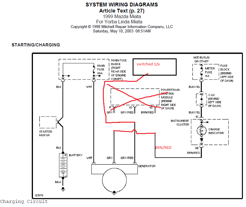
I think i described it pretty im depth in a PM to you... re-read that. Basically you want to cut 3 wires about an inch away from the harness/ECU... so you will have 3 cut off, loose wires hanging off the back of the ECU.... that's fine, or tape them up or something.
The other end of those 3 wires... (Grey, Grey/red, Brown/red).... you want to connect the grey to brown/red, and then the grey/red, extend that wire onto a switched 12V source that comes on when you switch the key to "on" or whatever.
There's 3 different plugs on the back of the ECU.... all 3 of these wires are all on the same one, but I can't remember which. Check that PM I sent to you again...it's all in there, in that ECU diagram I linked.
Reply
0
0
Thread Starter
Senior Member
iTrader: (3)
Joined: Nov 2009
Posts: 725
Total Cats: 5
From: Royal Palm Beach, FL
I know a keep throwing this pic up...but its seriously what i keep referring to explain what I did.

I think i described it pretty im depth in a PM to you... re-read that. Basically you want to cut 3 wires about an inch away from the harness/ECU... so you will have 3 cut off, loose wires hanging off the back of the ECU.... that's fine, or tape them up or something.
The other end of those 3 wires... (Grey, Grey/red, Brown/red).... you want to connect the grey to brown/red, and then the grey/red, extend that wire onto a switched 12V source that comes on when you switch the key to "on" or whatever.
There's 3 different plugs on the back of the ECU.... all 3 of these wires are all on the same one, but I can't remember which. Check that PM I sent to you again...it's all in there, in that ECU diagram I linked.
I think i described it pretty im depth in a PM to you... re-read that. Basically you want to cut 3 wires about an inch away from the harness/ECU... so you will have 3 cut off, loose wires hanging off the back of the ECU.... that's fine, or tape them up or something.
The other end of those 3 wires... (Grey, Grey/red, Brown/red).... you want to connect the grey to brown/red, and then the grey/red, extend that wire onto a switched 12V source that comes on when you switch the key to "on" or whatever.
There's 3 different plugs on the back of the ECU.... all 3 of these wires are all on the same one, but I can't remember which. Check that PM I sent to you again...it's all in there, in that ECU diagram I linked.
http://www.radioshack.com/product/in...odsInSession=1
Reply
0
0
not sure.... i used the one from DIYAutotune's site and only have exp with that one.
http://www.diyautotune.com/catalog/u...tune-p-67.html
http://www.diyautotune.com/catalog/u...tune-p-67.html
Reply
0
0
Thread Starter
Senior Member
iTrader: (3)
Joined: Nov 2009
Posts: 725
Total Cats: 5
From: Royal Palm Beach, FL
for the db15, am i supposed to wire the 12v and ground to a 12v and ground or are those wires sources for 12v and ground i can tap into?
-also, where do i dl the tuning software? diy website? they also have base maps for me to run stock config?
-also, where do i dl the tuning software? diy website? they also have base maps for me to run stock config?
Reply
0
0
those are sources you can tap into.
the pdf should have all that info. I have an updated one here:
http://www.boostedmiata.com/gallery2...1_0v1.pdf.html
the pdf should have all that info. I have an updated one here:
http://www.boostedmiata.com/gallery2...1_0v1.pdf.html
Reply
0
0
Thread Starter
Senior Member
iTrader: (3)
Joined: Nov 2009
Posts: 725
Total Cats: 5
From: Royal Palm Beach, FL
i chose the ini that i downloaded from the write up and no go.
i dont see the one its telling me to choose in my list of ecudef either
http://i90.photobucket.com/albums/k254/los561/ecu.jpg
http://i90.photobucket.com/albums/k254/los561/ecu2.jpg
am i supposed to connect anyway after selecting the downloaded .ini file that is in the ms2 extras?
i dont see the one its telling me to choose in my list of ecudef either
http://i90.photobucket.com/albums/k254/los561/ecu.jpg
http://i90.photobucket.com/albums/k254/los561/ecu2.jpg
am i supposed to connect anyway after selecting the downloaded .ini file that is in the ms2 extras?
Reply
0
0
Thread Starter
Senior Member
iTrader: (3)
Joined: Nov 2009
Posts: 725
Total Cats: 5
From: Royal Palm Beach, FL
the car wont idle, i changed timing settings to 10 fixed table and tried to crank it over like the pdf says. it will only stay on if i give it gas andkeep it above 1500, as soon as it gets close to 1k it drops down and stalls.
this is the msq and 2 data logs. 1 started loggin while motor was on, second i started before i cranked then let it stall.
this is the msq and 2 data logs. 1 started loggin while motor was on, second i started before i cranked then let it stall.
Reply
0
0


