
MS3 / CAN wiring question - multiple displays


Thread Starter
Elite Member
Joined: Sep 2011
Posts: 1,647
Total Cats: 446
From: Sierra Vista, AZ
VVT swapped NA running on MS3/MS3X.
For the last couple of years, I've been running the Perfect Tuning gauge with my MS3 with no issues. This is how I currently have it wired:
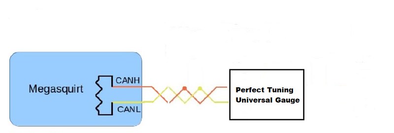
It's my understanding of CAN that the Perfect Tuning gauge is acting as a terminus for the CAN bus. Otherwise, it shouldn't work, right?
I've recently acquired a Racecapture Track Mk3 from Autosport Labs for data, and I would like to retain the functionality of the PT gauge. My understanding is that the Track Mk3 is also designed to act as a terminus for CAN.
This is how the MS manuals advise to string CAN devices along the bus:

Researching has led to some conflicting information on how multiple devices need to be wired, when those devices are designed to act as a CAN bus terminus. My question is: can I just wire the Track into the current system, like this (call this Option 1)

Or do I need to add a resistor terminus like this? (call this Option 2)

Hoping to hear from someone who has done something similar and got everything working properly.
For the last couple of years, I've been running the Perfect Tuning gauge with my MS3 with no issues. This is how I currently have it wired:
It's my understanding of CAN that the Perfect Tuning gauge is acting as a terminus for the CAN bus. Otherwise, it shouldn't work, right?
I've recently acquired a Racecapture Track Mk3 from Autosport Labs for data, and I would like to retain the functionality of the PT gauge. My understanding is that the Track Mk3 is also designed to act as a terminus for CAN.
This is how the MS manuals advise to string CAN devices along the bus:
Researching has led to some conflicting information on how multiple devices need to be wired, when those devices are designed to act as a CAN bus terminus. My question is: can I just wire the Track into the current system, like this (call this Option 1)
Or do I need to add a resistor terminus like this? (call this Option 2)
Hoping to hear from someone who has done something similar and got everything working properly.
Reply
 0
0

0


Some devices have an option to enable/disable a 120ohm resistor in their software. And by some devices, I mean AiM displays. I'm not sure on the Race Capture device, but something to look into. I'll let others speak on how to properly wire it.
Reply
0
0
Thread Starter
Elite Member
Joined: Sep 2011
Posts: 1,647
Total Cats: 446
From: Sierra Vista, AZ
It's wired exactly as pictured in post #2.
Parallel/Series doesn't quite apply to a CAN bus as I understand things, and I fully admit to barely understanding what's going on. CAN is still mostly sorcery in my mind. According to the research I've done, the bus has to have a terminus at both ends, in my case the MS3 and the Perfect Tuning gauge. The ASL Track Mk3 has the ability to act as a terminus, but I have that feature disabled for my configuration so it's merely a device along the bus.
Edit: the 120 ohm resistor Curly mentioned is what creates the terminus at the end of the bus. With the RaceCapture devices, this feature is controlled by the app.
Reply
0
0
All-round "Good Guy"

Joined: Dec 2009
Posts: 1,036
Total Cats: 266
From: Brisbane, AUSTRALIA
I'm surprised that software can be used to control the resistor's physical connection between the CAN bus Hi and Low circuits?
The easiest way to think of a CAN bus is like Roda's last picture, where one end of the bus is terminated at the MS and the other end is terminated by a 121Ohm resistor, or device that also has a CAN bus terminator.
You can add other devices along the bus by wiring them up to the CAN Hi and Low wires.
If these devices also have a CAN bus terminator in them, it must be disabled.
If you're lucky, the device has a jumper and you can switch it to the no-Terminator position.
If not, you can remove the 121Ohm resistor that joins the CAN bus Hi and Low circuits (desolder it, cut it off with side-cutters, or if it's one of those teeny-tiny resistors, cut it in half with a scalpel so that it no longer connects the wires).
Reply
0
0

This device should have some desirable properties that make it as similar to a mechanical relay as possible in terms of how it behaves as a switch (but with the added advantage of using less current than a relay coil on the �activation� part). Usually this is a type of IC known aptly as an �analogue switch.�
Reply
0
0

Thread
Thread Starter
Forum
Replies
Last Post


