
Timing errors with AEM EMS-4 (crank sensor)


http://img22.imageshack.us/img22/9524/photo1gb.jpg
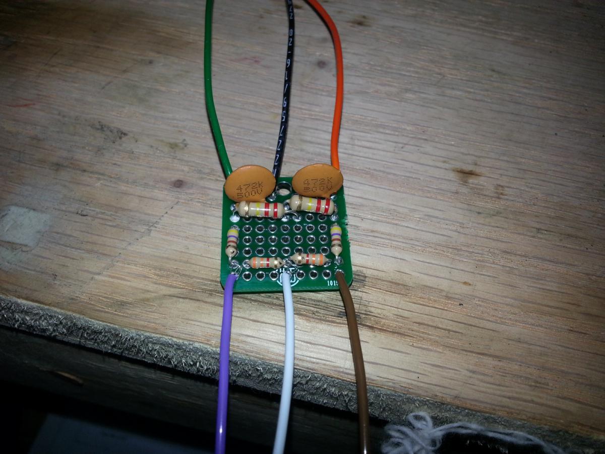
Red is 12v, Black is ground, white is the signal wire.
The resistor connected to the red wire that has heat shrink covering the band is the 3.3k. The Band that is covered is the GOLD one.
So from left to right:
GOLD-RED-ORANGE-ORANGE
GOLD-BROWN-BLUE-YELLOW
GOLD-YELLOW-RED-ORANGE
4.7uf CAP
I may have just noticed a problem. The circuit calls for 4.7nf not uf.
Last edited by miatauser123; Apr 3, 2013 at 12:51 AM.
Reply
 0
0

0
http://img22.imageshack.us/img22/9524/photo1gb.jpg
Red is 12v, Black is ground, white is the signal wire.
The resistor connected to the red wire that has heat shrink covering the band is the 3.3k. The Band that is covered is the GOLD one.
So from left to right:
GOLD-RED-ORANGE-ORANGE
GOLD-BROWN-BLUE-YELLOW
GOLD-YELLOW-RED-ORANGE
4.7uf CAP
I may have just noticed a problem. The circuit calls for 4.7nf not uf.
Reply
0
0
Hmmm I'm still getting a few errors (5-6 total at most) before the car is completely warmed up, but after that it doesn't seem to get any more. I can rev it all i want after that and I don't get any errors...any ideas?
P.S. I found out today that the alternator doesn't charge if gauge cluster isn't plugged in. May save someone from panicking and rummaging through wires in the engine bay. lol.
P.S. I found out today that the alternator doesn't charge if gauge cluster isn't plugged in. May save someone from panicking and rummaging through wires in the engine bay. lol.
Reply
0
0

Yeah, the 4.7uF will be an issue since it'll take forever to charge up. Radioshack had them (shocking, I know) for me locally. It'll be a small brown thing, and make sure that you get 4.7nF (.0047uF) because I was off a decimal point when I got the caps the first time.
Reply
0
0
Well - I'm an idiot. I had never used the "NF" measurement before... Usually it's 1 Farad. I'll swap it over tonight and let you know the results. I timed it and I'm getting 11 errors in about 60 seconds of idle without a filter (cold car).
Reply
0
0
SI Prefixes:
milli = m = 10^-3
micro = u = 10^-6
nano = n = 10^-9
pico = p = 10^-12
You will almost never see whole Farad capacitors because it is an insane amount of energy. The formula was designed before there were any practical applications and you'll see most capacitors in the micro range. They are never labeled nano, so you have to either convert from micro or from pico.
To put it more simply, AEM told me to not go above .01uF; you were at 4.7uF (500x). I used a 4.7nF which worked, which is 1000x smaller than the 4.7uF.
Orders of magnitude can break things fast.
Best of luck.
e: to quote wikipedia...
North American usage also avoids nanofarads: a capacitance of 1�10−9 F will frequently be indicated as 1000 pF; and a capacitance of 1�10−7 F as 0.1 μF.
Reply
0
0


Swapped it out with the 0.0047uf cap and shes perfect. Previous test showed (at idle) 11 timing errors in 60 seconds. New test shows 0 timing errors... ever. Success. Thank you GAMO
Reply
1
1


Reply
0
0

Looks like I need to build this circuit. I was getting about 70 timing errors per minute and pretty much constant sync errors counting up to 3 and resetting. Every time it would hit 3 sync errors it would miss something fierce, like hitting the brakes practically.
Reply
0
0
That was easy. Now I get about 10 timing errors per hour and sync errors just barely flickers between 0 and 1. No audible miss fires.
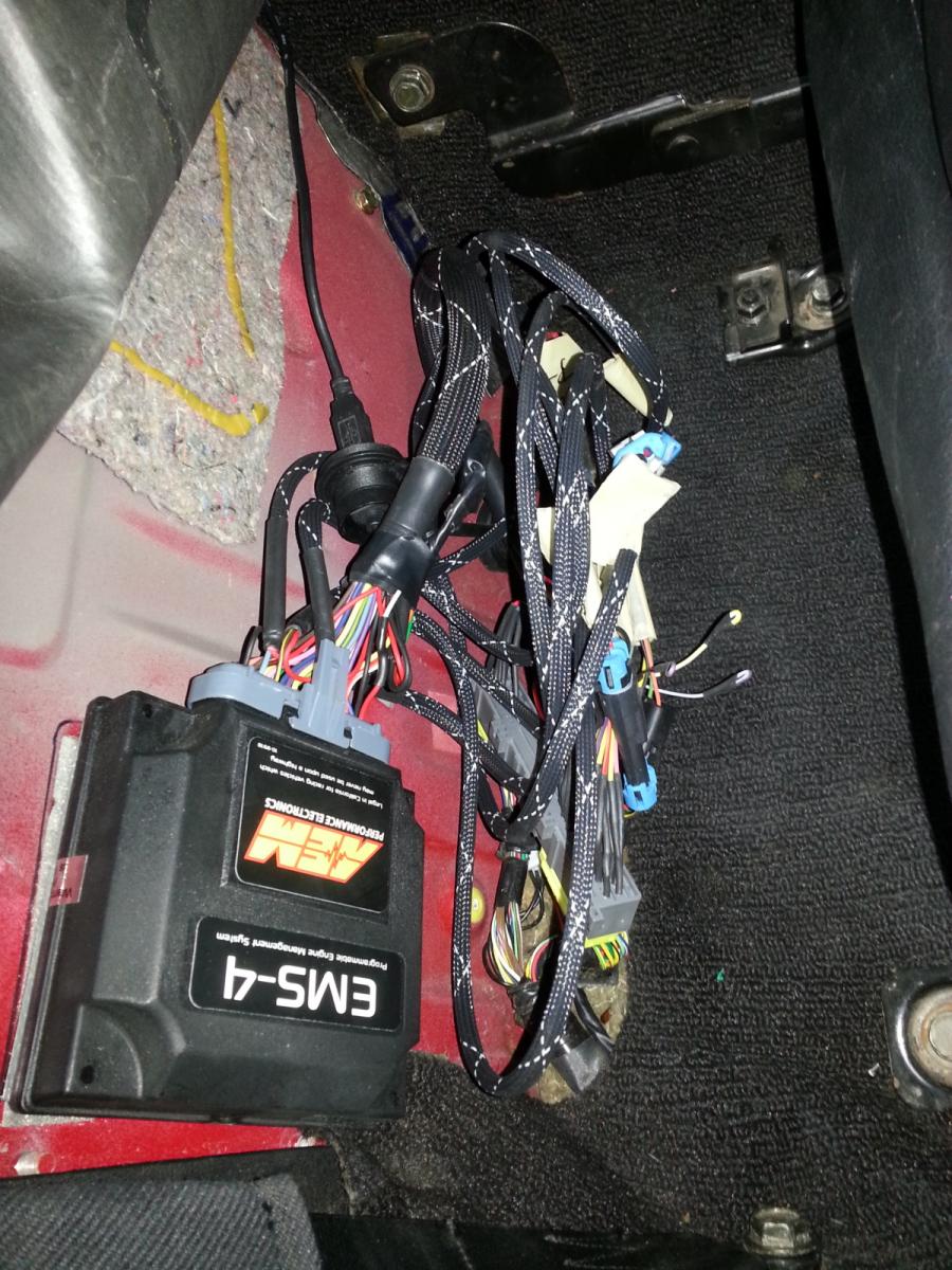
Black = Ground
White = +12
Brown = Cam sensor
Orange = cam ecu
Purple = crank sensor
green = crank ecu
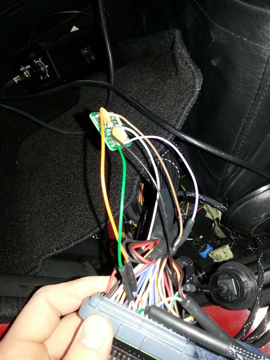
What a nest.
Black = Ground
White = +12
Brown = Cam sensor
Orange = cam ecu
Purple = crank sensor
green = crank ecu
What a nest.
Reply
0
0
No I used the stock wiring for the cam and just extended the wires to the crank with some milspec wire. The NA CAS isnt shielded. If it becomes a problem or if I ever rewire the car I'll run shielded all the way.
Reply
0
0
To update this thread. I added the intake manifold side ground because I appeared to be missing it. Now I get 1 timing error on startup and sync errors still flicker from 0 to 1 rapidly. HOWEVER I have what might be a bigger problem. With the car idling at 1krpm and the ignition timing locked at 10deg the timing marks are perfect, but if you rev it to ~2500 the advance slowly climbs to 12deg and we couldn't really see with the timing light as the revs went higher. This is an issue, is it caused by something changing in this circuit be it the pull-up voltage or the ground offset voltage or something. Could some electrical issue cause this circuit to do this? Is this a downfall of the circuit? or what? Car currently does not knock before redline or at peak torque.
Reply
0
0


