1.8 VVT motor into 1.6 car Advice welcome.


Thread Starter
Junior Member
Joined: Sep 2011
Posts: 135
Total Cats: -20
I think the milspec stuff has to be rated to like ~300*F
I take this stuff flying daily, next to a jet turbine; so I have 100% confidence of it lasting in my car.
Yeah that link is over the top, but I take some of the bigger ideas and try and filter it down to something more practical I can do.
I take this stuff flying daily, next to a jet turbine; so I have 100% confidence of it lasting in my car.
Yeah that link is over the top, but I take some of the bigger ideas and try and filter it down to something more practical I can do.
That link just makes me drool. The twisted pairs on the sensor wires is something I'll probably incorporate into this project actually.
Reply
 0
0

0


Thread Starter
Junior Member
Joined: Sep 2011
Posts: 135
Total Cats: -20
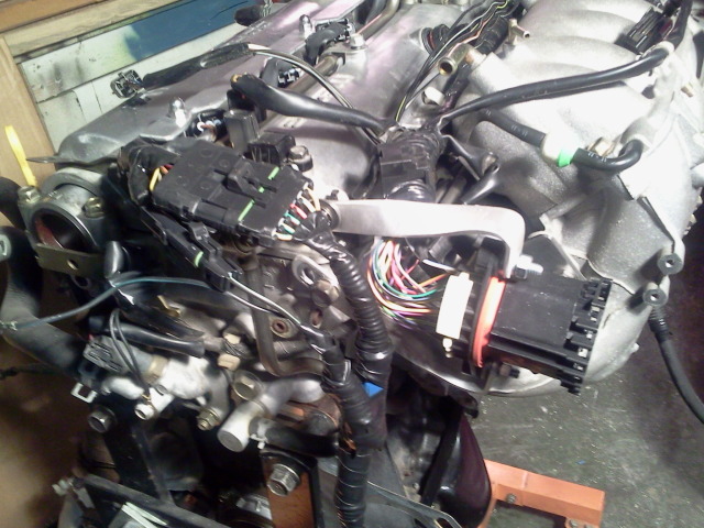
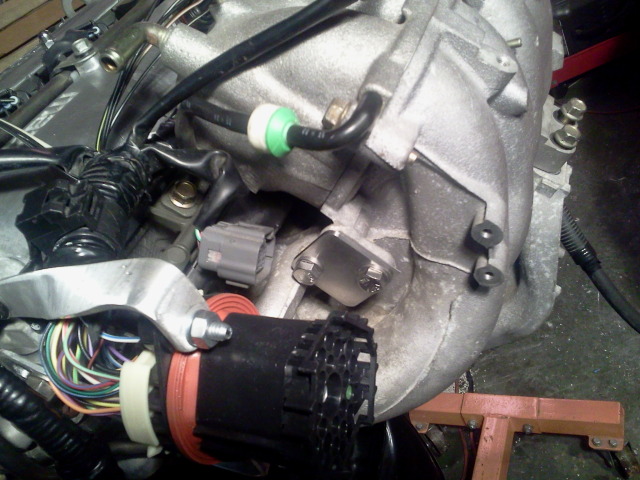
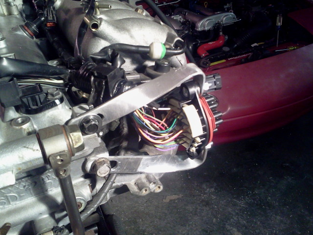
I've finished the main connector on the engine side. The ignition coils will be on a separate harness. The brackets look kind of funny but they work. They'll look better painted black. Loving the Weatherpacks.
Reply
0
0
Reply
0
0

Reply
0
0
Reply
0
0
Joined: Jun 2006
Posts: 29,085
Total Cats: 375
From: Republic of Dallas
As I understand it, the tach on a 1.6 is a totally seperate circuit that never sees the computator and goes straight from the coils to the gauge. I'm ending that in my car and running the tach off the computer using NB sensors.
Reply
0
0
Joined: Jun 2006
Posts: 29,085
Total Cats: 375
From: Republic of Dallas
Reply
0
0
the tach on the 90-95.5 is driven directly off the coils.
The dash tach is looking for 4 pulses per cycle. You need your signal input to cycle from low to high, ground to ~12v, in order for it to recieve one pulse.
So the tach signal acutally has power running through it; basically everytime the coil sparks, it's switched momentarily to 12v, where it then returns back to ground. The speed in which the coils fire and the signal getting switched from low to high sent out to the tach determines the needle poistion.
The reason we add the resistor is because the stock ECU provides a pull-up power for the tach signal, when we replace it with an aftermarket ECU, we tend to remove the pull-up.
So unless you build your ECU harness to provide that pull-up back to the B/W that leads to the ignitor/coils, we add it back in the diagnositics box between IG- (the tach signal to the dash) and B+ (12v).
Otherwise all 95.5+ miatas provide the tach output directly from the ECU.
Reply
0
0
Joined: Jun 2006
Posts: 29,085
Total Cats: 375
From: Republic of Dallas
the tach on the 90-95.5 is driven directly off the coils.
The dash tach is looking for 4 pulses per cycle. You need your signal input to cycle from low to high, ground to ~12v, in order for it to recieve one pulse.
So the tach signal acutally has power running through it; basically everytime the coil sparks, it's switched momentarily to 12v, where it then returns back to ground. The speed in which the coils fire and the signal getting switched from low to high sent out to the tach determines the needle poistion.
The reason we add the resistor is because the stock ECU provides a pull-up power for the tach signal, when we replace it with an aftermarket ECU, we tend to remove the pull-up.
So unless you build your ECU harness to provide that pull-up back to the B/W that leads to the ignitor/coils, we add it back in the diagnositics box between IG- (the tach signal to the dash) and B+ (12v).
Otherwise all 95.5+ miatas provide the tach output directly from the ECU.
The dash tach is looking for 4 pulses per cycle. You need your signal input to cycle from low to high, ground to ~12v, in order for it to recieve one pulse.
So the tach signal acutally has power running through it; basically everytime the coil sparks, it's switched momentarily to 12v, where it then returns back to ground. The speed in which the coils fire and the signal getting switched from low to high sent out to the tach determines the needle poistion.
The reason we add the resistor is because the stock ECU provides a pull-up power for the tach signal, when we replace it with an aftermarket ECU, we tend to remove the pull-up.
So unless you build your ECU harness to provide that pull-up back to the B/W that leads to the ignitor/coils, we add it back in the diagnositics box between IG- (the tach signal to the dash) and B+ (12v).
Otherwise all 95.5+ miatas provide the tach output directly from the ECU.
Reply
0
0

if you remove the factory ECU, the "trick" has been tricked...
for example, my B/W and tach output wires are tied together in my COP harness, but if I removed the 1K pull-up resistor that I added later, I'd be without a dash tach.
All you are doing by this is reconnecting the pull-up from the ECU to the tach output wire since you've gutted the ignitor where the connection had orginially been made.
This has been disscussed before.
Reply
0
0