

Abe's Coolant Re-route Project

Thread Starter

Joined: Aug 2006
Posts: 3,047
Total Cats: 13
From: San Diego, CA
Let's hope I don't have to rename this later to Abe's Coolant Re-route SNAFU
So, as many of you know, if you go to use the stock NB thermo housing, you're left with two options: Through the hood, or through the transmission. Actually, I've seen people make the upwards path work, and I think you could make the downwards one totally work, there's a lot more room in an NB than an NA.
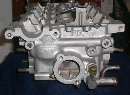
Note in all these photos, the head is upside down, you're looking at the rear of a VVT model, otherwise stock head.

Through the transmission...

...Or through the hood.
Additionally, to be chronographically representative here... There's the spacer for the heater hose. The most common solution is a spacer. The VVT head has a port in the side, I have no idea what for, but it's nice and thick and fairly easy to work with.

Port shown here with existing plug in it. Note, also, the plug to the intake side of the head with the plug.
FYI, do not try to take out the water feed there. I spent many an hour, with head, obscenely large pipe wrenches, etc, and only managed to break it - on a spare head.
Back to the story. So I take my junk VVT head, drill and tap the threads, squeeze my 1/2 NPT-to-barb fitting in there and find.... There's no room for the hose or clamp! SHOOT!
So I get the real head, and with great sweat and fear, drill an angled path. This takes a hefty drill and a well supported head (note the clamps) but works quite nicely, and gives you a convenient angle.


Tapped it:

It's pretty hard to get the tap in right. For that matter, it's hard to get the piece started in the hole after it's tapped. Perhaps making a flat before you start, or drilling a little ways with a bigger drill would help, but all I had access to was the standard "miata oil pan tap tubo return" set up, so I used it (Thanks FM!).

As you can see, the fitting ended up at a nice angle. I used the goo-type teflon sealant because I don't really trust my angled drilling.
Next post for water neck.
So, as many of you know, if you go to use the stock NB thermo housing, you're left with two options: Through the hood, or through the transmission. Actually, I've seen people make the upwards path work, and I think you could make the downwards one totally work, there's a lot more room in an NB than an NA.
Note in all these photos, the head is upside down, you're looking at the rear of a VVT model, otherwise stock head.
Through the transmission...
...Or through the hood.
Additionally, to be chronographically representative here... There's the spacer for the heater hose. The most common solution is a spacer. The VVT head has a port in the side, I have no idea what for, but it's nice and thick and fairly easy to work with.
Port shown here with existing plug in it. Note, also, the plug to the intake side of the head with the plug.
FYI, do not try to take out the water feed there. I spent many an hour, with head, obscenely large pipe wrenches, etc, and only managed to break it - on a spare head.
Back to the story. So I take my junk VVT head, drill and tap the threads, squeeze my 1/2 NPT-to-barb fitting in there and find.... There's no room for the hose or clamp! SHOOT!
So I get the real head, and with great sweat and fear, drill an angled path. This takes a hefty drill and a well supported head (note the clamps) but works quite nicely, and gives you a convenient angle.
Tapped it:
It's pretty hard to get the tap in right. For that matter, it's hard to get the piece started in the hole after it's tapped. Perhaps making a flat before you start, or drilling a little ways with a bigger drill would help, but all I had access to was the standard "miata oil pan tap tubo return" set up, so I used it (Thanks FM!).
As you can see, the fitting ended up at a nice angle. I used the goo-type teflon sealant because I don't really trust my angled drilling.
Next post for water neck.
Reply
 0
0

0

Thread Starter
Joined: Aug 2006
Posts: 3,047
Total Cats: 13
From: San Diego, CA
So back to water necks facing the wrong way. I was going to go "uphill" then I decided to bother Super Moderator Joe P. for his stockpile of parts, and saw his 1.6l thermo housing.... And had ideas.

I tried cutting off some of the flanges and extentions, etc, with the band saw, which resulted in my getting lots of practice putting the band saw blade back on after it hopped the wheels, and in nearly burning Joe in thanks for his part when he picked it up.
Then I got out the 3" HF disc cutter, and air tools did more in about 1.5 minutes than the previous hour had accomplished.

HF, God's gift to the poor. Note, the die grinder bit came from ebay. Grand total: ~$20 in tools. Note also the knocked off water T, again, don't try to remove these, cut them out and save yourself an hour and two broken screw drivers thinking it's almost there. It's not.
Now comes the depressing part - sorry all you people without a lathe, but this is really key:

If you try this: BE AWARE HOW MUCH YOU TAKE OFF! I only have ~.030-035" wall thickness because I was obsessing with trying to clean things up.

After smoothing out the shaft, leaving a bump at the end as a "hose stop" to keep me from trying to put the entire hose on the outlet...., I put two barbs on the front. Probably these will do more harm than good, but, they let me part the neck off the old flange and should keep the hose from slipping off when clamped.

Before any touch up.
A couple minutes with a wire brush in a drill press (another one of those things which is WAY more useful than you can ever guess) has it looking much better.


Now to check that pesky temp sensor...

Oh yeah, it's tight. So, I decided to slot the mounting holes with the aforementioned die grinder. It worked stunningly well. You could use a dremel, but it'll take hours not minutes. And you already bought that set of 5 carbide bits on ebay anyway, right? For this you'll want a really thin one, just smaller than the bolt.

NOTE: Don't make Abe's mistakes (someday, everyone will wear DMAM bracelets instead of WWJD) - see how the slots come in close? Don't do this. I envision it giving me problems where I can't get a seal. I'm almost tempted to buy another and make the piece from scratch. I'm hoping RTV will answer all my prayers, especially if the thermo itself does some sealing.

The bolts end up right on the outside edge, so start there. Put in two studs, rotate it, see where it needs to be, mark it with a pen, go grind. It's faster and safer overall this way.

Final piece, showing alignment as mounted.

Note flat spot ground on side to clear temp sensor. Also, tighten temp sensor to get just the right flat facing the housing.

Protrusion towards firewall is minimal....
I tried cutting off some of the flanges and extentions, etc, with the band saw, which resulted in my getting lots of practice putting the band saw blade back on after it hopped the wheels, and in nearly burning Joe in thanks for his part when he picked it up.
Then I got out the 3" HF disc cutter, and air tools did more in about 1.5 minutes than the previous hour had accomplished.
HF, God's gift to the poor. Note, the die grinder bit came from ebay. Grand total: ~$20 in tools. Note also the knocked off water T, again, don't try to remove these, cut them out and save yourself an hour and two broken screw drivers thinking it's almost there. It's not.
Now comes the depressing part - sorry all you people without a lathe, but this is really key:
If you try this: BE AWARE HOW MUCH YOU TAKE OFF! I only have ~.030-035" wall thickness because I was obsessing with trying to clean things up.
After smoothing out the shaft, leaving a bump at the end as a "hose stop" to keep me from trying to put the entire hose on the outlet...., I put two barbs on the front. Probably these will do more harm than good, but, they let me part the neck off the old flange and should keep the hose from slipping off when clamped.
Before any touch up.
A couple minutes with a wire brush in a drill press (another one of those things which is WAY more useful than you can ever guess) has it looking much better.
Now to check that pesky temp sensor...
Oh yeah, it's tight. So, I decided to slot the mounting holes with the aforementioned die grinder. It worked stunningly well. You could use a dremel, but it'll take hours not minutes. And you already bought that set of 5 carbide bits on ebay anyway, right? For this you'll want a really thin one, just smaller than the bolt.
NOTE: Don't make Abe's mistakes (someday, everyone will wear DMAM bracelets instead of WWJD) - see how the slots come in close? Don't do this. I envision it giving me problems where I can't get a seal. I'm almost tempted to buy another and make the piece from scratch. I'm hoping RTV will answer all my prayers, especially if the thermo itself does some sealing.
The bolts end up right on the outside edge, so start there. Put in two studs, rotate it, see where it needs to be, mark it with a pen, go grind. It's faster and safer overall this way.
Final piece, showing alignment as mounted.
Note flat spot ground on side to clear temp sensor. Also, tighten temp sensor to get just the right flat facing the housing.
Protrusion towards firewall is minimal....
Reply
0
0


--Ferdi
Reply
0
0

Thread Starter
Joined: Aug 2006
Posts: 3,047
Total Cats: 13
From: San Diego, CA
Then I had an issue! My nuts were too big!

I coudln't turn them. Now, these were 13 mm nuts. I have a feeling 12 mm would work just fine. I may try them.
I took some OEM bolts, the flanged kind...., and turned down the flange. I noticed the bolts themselves aren't all that sharply cornered, so I turned the whole thing down, I don't know what too, but smaller than the corners, as pictured here:

I noticed the studs were hard to get out, so, I thought I should chase the threads in the holes first, which I did. Then I put it all together, and it looks awesome!

You need an open wrench to tighten it up, but it's not otherwise bad. Perhaps this will suck when it's on the car? I should look for 11mm nuts for those stud but have a feeling it will be hard to find. Still, that would be the most clean solution.
I end up with good clearance on the sensor.

Now all that remains is putting a plug where the T used to be that I'd cut off to make it fit in the lathe.
This seems to be a good design. Flow past the temp sensor, flow past the thermostat (with the heater and oil heater feeds there) and I think it gives me a nice starting place to route the piping up to the front. I would like to sneak it between mani and head as I've seen someone on the board do on his 7 project - wish I remembered where I'd seen it.
I'll post more when there's more to tell, or answer questions as I see them.
I coudln't turn them. Now, these were 13 mm nuts. I have a feeling 12 mm would work just fine. I may try them.
I took some OEM bolts, the flanged kind...., and turned down the flange. I noticed the bolts themselves aren't all that sharply cornered, so I turned the whole thing down, I don't know what too, but smaller than the corners, as pictured here:
I noticed the studs were hard to get out, so, I thought I should chase the threads in the holes first, which I did. Then I put it all together, and it looks awesome!
You need an open wrench to tighten it up, but it's not otherwise bad. Perhaps this will suck when it's on the car? I should look for 11mm nuts for those stud but have a feeling it will be hard to find. Still, that would be the most clean solution.
I end up with good clearance
on the sensor.Now all that remains is putting a plug where the T used to be that I'd cut off to make it fit in the lathe.
This seems to be a good design. Flow past the temp sensor, flow past the thermostat (with the heater and oil heater feeds there) and I think it gives me a nice starting place to route the piping up to the front. I would like to sneak it between mani and head as I've seen someone on the board do on his 7 project - wish I remembered where I'd seen it.
I'll post more when there's more to tell, or answer questions as I see them.
Reply
0
0
Thread Starter
Joined: Aug 2006
Posts: 3,047
Total Cats: 13
From: San Diego, CA
Thanks! It really came out better than I was expecting. Which was for nothing to come of it at all. :-)
It was SUPER tight. I think it'll end up working well. I've had a hose on it, what worries me most is it is smaller than the OEM hose! So I'll need a huge clamp or to change the fitting. I hope I don't have to make one. Worst case, I can run a long 3/8 brass extension, and deal with it over by the turbo.
Reply
0
0
 . And, just to clarify, I am not doing a reroute on my Protege as it's correct to begin with, lol. But, the BP4W head I used is missing the fitting for the heater core that the stock BP05 Protege head incorporates into that pressed-in fitting.
--Ferdi
Reply
0
0
Thread Starter
Joined: Aug 2006
Posts: 3,047
Total Cats: 13
From: San Diego, CA
Odds and ends:
If someone had a lathe and wanted a side job, doing these would take a few hours - not a money maker, but something to do and would help people out.
I'm going to start with one of those Mazda dual-thermo-thermos. I've been running a 160 degree thermo for years - and while it truly makes the linearized water temp gauge in my dash look amazing to sit there always on beginning of the waves when it opens and on the thermometer when the fans come on.... The truth is, all it means is I'm beating on a cold engine all the time, and the heater doesn't work well.
Again: With a 160* thermostat, your life is exactly the same, but you are always cold because your heater core is the same temperature you are!

It seems like an awesome idea, for an around town thing. And the flow area is pretty comparable to a larger one, since... there are two. If you really look at it, you might agree.

Spiffy, huh? I guess I don't care about "tight control" so much, but I think maybe it'll make the dip when the thermo first opens less drastic. Other than being 160, I've been super happy with my NAPA unit for like 5+ years.
Head Gaskets!
As Joe pointed out recently, of the many water passages:

some are made available to the pre-VVT motors, and others to late model heads, in and effort to redirect flow where it should be for a RWD install (front thermo).
I would not want to get the wrong one on my freshly re-routed car!

99 gasket on top, late model (from VVT head, presumed original) on bottom.
It's pretty obvious - neither has many openings on the intake side compared to the exhaust, ok, cool the valves. The "front" of the motor, however, has more water in the earlier gaskets - perhaps leading to decreased flow in stock motors, but increased and more even flow in the rerouted ones.
Handy Dandy Chart:

It sure looks like there isn't a lot of room for improvement, for a rerouted car, over the OEM gasket. It does just what you want, cools front to back and a bit extra on the exhaust side. Sure, it could do with a LITTLE less flow in the rear, but, overall it's not bad. To keep things even you'd want a bit more in back so it doesn't see only hot water.
The fixed one (VVT) looks great if you're skipping the reroute.
I guess I'll be using the gasket I bought, unless someone has some better reasoning. I know there's a thread somewhere on this, but I didn't like the pics as much - perhaps I should give it another look.
If someone had a lathe and wanted a side job, doing these would take a few hours - not a money maker, but something to do and would help people out.
I'm going to start with one of those Mazda dual-thermo-thermos. I've been running a 160 degree thermo for years - and while it truly makes the linearized water temp gauge in my dash look amazing to sit there always on beginning of the waves when it opens and on the thermometer when the fans come on.... The truth is, all it means is I'm beating on a cold engine all the time, and the heater doesn't work well.
Again: With a 160* thermostat, your life is exactly the same, but you are always cold because your heater core is the same temperature you are!
It seems like an awesome idea, for an around town thing. And the flow area is pretty comparable to a larger one, since... there are two. If you really look at it, you might agree.
Spiffy, huh? I guess I don't care about "tight control" so much, but I think maybe it'll make the dip when the thermo first opens less drastic. Other than being 160, I've been super happy with my NAPA unit for like 5+ years.
Head Gaskets!
As Joe pointed out recently, of the many water passages:
some are made available to the pre-VVT motors, and others to late model heads, in and effort to redirect flow where it should be for a RWD install (front thermo).
I would not want to get the wrong one on my freshly re-routed car!
99 gasket on top, late model (from VVT head, presumed original) on bottom.
It's pretty obvious - neither has many openings on the intake side compared to the exhaust, ok, cool the valves. The "front" of the motor, however, has more water in the earlier gaskets - perhaps leading to decreased flow in stock motors, but increased and more even flow in the rerouted ones.
Handy Dandy Chart:
It sure looks like there isn't a lot of room for improvement, for a rerouted car, over the OEM gasket. It does just what you want, cools front to back and a bit extra on the exhaust side. Sure, it could do with a LITTLE less flow in the rear, but, overall it's not bad. To keep things even you'd want a bit more in back so it doesn't see only hot water.
The fixed one (VVT) looks great if you're skipping the reroute.
I guess I'll be using the gasket I bought, unless someone has some better reasoning. I know there's a thread somewhere on this, but I didn't like the pics as much - perhaps I should give it another look.
Last edited by AbeFM; Mar 19, 2010 at 03:24 PM.
Reply
0
0
Thread Starter
Joined: Aug 2006
Posts: 3,047
Total Cats: 13
From: San Diego, CA
Speaking of fittings, does anyone have any idea what fitting to use for the heater hose? It ends up in a very OEM like location.
Reply
0
0
Reply
0
0


Thread Starter
Joined: Aug 2006
Posts: 3,047
Total Cats: 13
From: San Diego, CA
Ah, awesome, thanks guys.
I had to update my pics - apparently some of the stuff I thought was water was actually oil return holes - so there's less flow even than I thought.
I'll fix the smaller pictures later, for now just the one with everything.
I had to update my pics - apparently some of the stuff I thought was water was actually oil return holes - so there's less flow even than I thought.
I'll fix the smaller pictures later, for now just the one with everything.
Reply
0
0
Thread Starter
Joined: Aug 2006
Posts: 3,047
Total Cats: 13
From: San Diego, CA
Question: Do they take ANY water out of the front on the FWD cars? I'm trying to picture the flow, on the VVT set up, it looks like without the heater like there'd be a bit of a dead spot in the back. I guess if I'm using that FWD gasket, I should try to make the flow as well as I can. I'm glad to see they take the heater off in the rear, I feel better about doing it myself..
Reply
0
0
Question: Do they take ANY water out of the front on the FWD cars? I'm trying to picture the flow, on the VVT set up, it looks like without the heater like there'd be a bit of a dead spot in the back. I guess if I'm using that FWD gasket, I should try to make the flow as well as I can. I'm glad to see they take the heater off in the rear, I feel better about doing it myself..
--Ferdi
Reply
0
0
Don't need a lathe, did mine with a cut off wheel and a angle grinder. See third pic down in this thread.
https://www.miataturbo.net/forum/t31042/
https://www.miataturbo.net/forum/t31042/
Reply
0
0
Thread Starter
Joined: Aug 2006
Posts: 3,047
Total Cats: 13
From: San Diego, CA
Wow, nice job!
But... why did you have the second housing floating out there in space? I'm thinking of of putting the thermo in there, bingo-bam-done. Then it's just hose up to the front.
You can steal my stolen drill-into-the-head idea for running the heater, or get the protege part shown above and put it in.
What I don't get is how you got that T out. Really. How?
Reply
0
0


