
My Reroute drawing


 03-03-2009, 07:06 PM
#222
Junior Member

Join Date: Sep 2008
Location: Austin, TX
Posts: 100
Total Cats: 0
First I want everyone to know how impressed I am with Mazda's ability to put sharp edges on everything you touch while installing this spacer. After 7 years of turning a wrench for a living and over 25 of turning for my own projects I can say that not even an air cooled VW has more sharp edges to rub up against. I also want to know is anyone can do this job with the valve cover and coil packs still installed on the engine.
The EGR on the 1.8 will no be compatible with the spacer if you have to run your EGR you need a different solution. The temp sensor bug that BEGi put on the prototype needs to be shaved down to the body of the spacer and to be a flat surface for the temp sensor.
The locations for the sensor, heater port and extra temp sensor all seem to be good as long as the extra sensor is added at the time of install or while the engine is out of the car.
To make the install as easy as possible with the engine in the car I hate to say it but hustler is half right a stud for the lower mounting point would make the install much easier as you would have a point to rest the spacer as you line up the bolt 2 studs and you would not be able to swap this part on and off the head while it is in the car.
I will try to get to BEGi on Thursday or Friday at the latest to get a production version of the part and the rest of the kit.
Photos to follow once the production version of the kit is installed.
The bottom fastener need to be a 85mm bolt or a 95 mm long stud

Reply
 0
0

0
03-05-2009, 03:36 PM
#225
Boost Pope


iTrader: (8)
Join Date: Sep 2005
Location: Chicago. (The less-murder part.)
Posts: 33,046
Total Cats: 6,607
Examples:
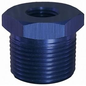
XRP 991203 (Bushing, Reducer 3/8 Male to 1/8 Female NPT - Aluminum) - LPI Racing
3/8"P TO 1/8"P only $3.26 - NPT Reducer Bushings
661570 - Russell AN & NPT Adapter Fittings
Alternately, a 1/8" NPT hole would be very easy for the end user to drill and tap. You could put it wherever you wanted it.
Reply
0
0
 03-05-2009, 04:03 PM
#227
Former Vendor

Join Date: Jun 2006
Location: Bell Tuning & Performance
Posts: 1,337
Total Cats: -99
I'm liking that concept a lot. My only concern is that with the stock CLT sensor being of a non-tapered thread and shoulder-sealing design, the thread break at the outer edge might prevent it from sealing properly. After the pilot hole is drilled, but before the tapping operation is done (so it's easier to remain concentric) why not run a 90� tapered countersink a mm or so into the hole? That way, after the threading tap is run, there will still be a clean, smooth surface for the shoulder of the sensor to seal against?
Stephanie
Reply
0
0
03-05-2009, 04:16 PM
#228
Something like this works great for deburring and countersinking a part in a mill repeatably and accurately in about 1 second. Just setup your stops on the head and plunge to debure and countersink simultaneously. Great tool to use anytime you're making circles.
Enco - Guaranteed Lowest Prices on Machinery, Tools and Shop Supplies
BTW-how do yall go about making these? Are yall turning out the part in a lathe with a cutter and boring bar, cutting the relieve for the thermostat in a lathe, then face it off, then cut it off? I guess then it goes in a mill to get the two slots cut in it's side. I'm not sure how yall are cutting those slots on the side. Are you plunging a 2 flute right into the parts, then out? It would be faster/cheaper/easier to just clamp the part in the vise and mill a flat on either side for the bolt to go through. It wouldn't be round, but that wouldn't matter either. What about the holes for the sensors, are these being done by hand or in a mill? Would be easy enough to drill the holes for the sensors in the mill after cutting the reliefs for the bolts.
Reply
0
0
03-05-2009, 06:09 PM
#232
Boost Czar

iTrader: (62)
Join Date: May 2005
Location: Chantilly, VA
Posts: 79,501
Total Cats: 4,080
 We both probably had our spacers longer than hustler...just never installed.
Hell I learned about the reroute concept back in '05 when I turboed my car. I'm sure the idea for our motor is almost 20 years old.
Reply
0
0
 03-05-2009, 06:50 PM
#234
Tour de Franzia
iTrader: (6)
Join Date: Jun 2006
Location: Republic of Dallas
Posts: 29,085
Total Cats: 375
Do you want friend status rejected on facebook? Look ************, I've been rubbing that test-gel on my ***** for a long ******* time ok, lets not bring that into this ****. Seriously, I'm impotent.
Reply
0
0
03-05-2009, 06:52 PM
#235
Tour de Franzia
iTrader: (6)
Join Date: Jun 2006
Location: Republic of Dallas
Posts: 29,085
Total Cats: 375
PM me nudes of your mother and I'll feel better about our recent altercation.
Reply
0
0
03-06-2009, 11:57 AM
#236
Former Vendor
Join Date: Jun 2006
Location: Bell Tuning & Performance
Posts: 1,337
Total Cats: -99
I'm liking that concept a lot. My only concern is that with the stock CLT sensor being of a non-tapered thread and shoulder-sealing design, the thread break at the outer edge might prevent it from sealing properly. After the pilot hole is drilled, but before the tapping operation is done (so it's easier to remain concentric) why not run a 90� tapered countersink a mm or so into the hole? That way, after the threading tap is run, there will still be a clean, smooth surface for the shoulder of the sensor to seal against?
Stephanie
Reply
0
0
03-06-2009, 08:39 PM
#237
Boost Pope
iTrader: (8)
Join Date: Sep 2005
Location: Chicago. (The less-murder part.)
Posts: 33,046
Total Cats: 6,607
Does anybody have one lying around that they can take a picture of? I'm thinking that I might be off-base here. Is there a radiused transition between the threaded shaft and the flat face?
EDIT: Nevermind. I finally found a picture of one and have confirmed that I am, in fact, a retard.
The part looks great. How much, and when can I get one?
Last edited by Joe Perez; 03-07-2009 at 08:37 AM.
Reply
0
0
03-07-2009, 12:01 PM
#238
Junior Member
Join Date: Sep 2008
Location: Austin, TX
Posts: 100
Total Cats: 0
Looks like the moving of all the ports to the same side of the spacer makes the spacer unusable. The temp sensor now interferes with the bell housing. Did I miss where the reason was given for the move?
Reply
0
0
03-07-2009, 10:28 PM
#239
Boost Pope
iTrader: (8)
Join Date: Sep 2005
Location: Chicago. (The less-murder part.)
Posts: 33,046
Total Cats: 6,607
Huh. I was so fixated on the shape of the CLT sensor hole that I failed to notice the location of the holes. Eraser-X is right.
Let's step back here for a second. I've done a quick and dirty sketch which I think describes everything we were speaking about earlier. It's not perfectly to scale (I'm working on my laptop in a hotel room, so I don't have parts on-hand to measure) but it's pretty close and I believe it conveys the basic design that we'd all agreed upon. A picture is worth a thousand words, right?
Here's the spacer viewed from behind the engine, looking forward from the driver's side:

And again, from behind the engine, from the passenger's side:

So, on the driver's side, we have one 3/8" NPT hole, mounted at horizontal, into which a hose-barb fitting will be inserted to attach the heater core supply hose.
On the passenger's side, we have the M12 hole (with flat surround) for the stock coolant sensor positioned above horizontal, to put the CLT sensor in roughly the stock location. We then have another 3/8" NPT hole, below horizontal, to accommodate whatever accessory somebody wants to install, such as an aftermarket CLT sensor.
I believe there's enough space left over that if someone wants to drill an additional hole (for a 1/8" NPT, or a 1.6 fanswitch, or 1/8" BSP, or whetever) that they can do so.
Thoughts?
Let's step back here for a second. I've done a quick and dirty sketch which I think describes everything we were speaking about earlier. It's not perfectly to scale (I'm working on my laptop in a hotel room, so I don't have parts on-hand to measure) but it's pretty close and I believe it conveys the basic design that we'd all agreed upon. A picture is worth a thousand words, right?
Here's the spacer viewed from behind the engine, looking forward from the driver's side:
And again, from behind the engine, from the passenger's side:
So, on the driver's side, we have one 3/8" NPT hole, mounted at horizontal, into which a hose-barb fitting will be inserted to attach the heater core supply hose.
On the passenger's side, we have the M12 hole (with flat surround) for the stock coolant sensor positioned above horizontal, to put the CLT sensor in roughly the stock location. We then have another 3/8" NPT hole, below horizontal, to accommodate whatever accessory somebody wants to install, such as an aftermarket CLT sensor.
I believe there's enough space left over that if someone wants to drill an additional hole (for a 1/8" NPT, or a 1.6 fanswitch, or 1/8" BSP, or whetever) that they can do so.
Thoughts?
Reply
0
0
03-07-2009, 11:00 PM
#240
2 Props,3 Dildos,& 1 Cat
iTrader: (8)
Join Date: Jun 2005
Location: Fake Virginia
Posts: 19,338
Total Cats: 573
only that the 2001 coolant sensor is on the upper left (drivers side), but that could be made an easy swap by putting the thermostat groove in both sides and running the spacer flipped around so that your pictures are from the front of the car.
Reply
0
0


