When you click on links to various merchants on this site and make a purchase, this can result in this site earning a commission. Affiliate programs and affiliations include, but are not limited to, the eBay Partner Network.
I've decided to create a new sticky, as the original thread has gotten a bit murky over the years. Note that the specific directions here apply to the B6 / BP-series engines (NA and NB), but the basic principles are relevant to any modern engine.
I am open to conversation and suggestions, but please don't clutter this thread up with crap. I'm going to keep this thread clean. I will be updating this post periodically as new information or persuasive arguments are made available. Also, I am not a professional engine-designer or mechanical engineer, I am merely attempting to condense information from a wide number of sources into a cohesive reference article.
SCOPE: What's the problem that the OEM solution addressed? Blowby. Combustion gasses (containing moisture and acidic vapors) escaping past the rings and contaminating the oil (and the earth's atmosphere; remember, this is technically an emissions-control device.). The OEM design solves this issue by drawing this gas into the intake manifold and recombusting it.
Why is this not adequate for engines operating at sustained high RPM? Because we also have a higher-than-average amount of atomized / vaporized oil floating around, and if we draw it all into the intake manifold, it fouls up the works.
Why is this not adequate for forced-induction engines? Because the PCV valve (if operating properly) will be fully closed when in boost, so blowby gasses and oil vapor will be forced out backwards into the low-pressure side of the intake piping.
First, a few basic concepts:
In the OEM design, there are two ventilation ports on the valve cover.
The port on the intake side of the engine is an outlet, to release gasses from the valve cover into the intake manifold. The PCV valve regulates this flow, preventing it from acting like a huge vacuum leak at idle. If you are not familiar with the operation of a PCV valve, the short version: It allows a high flow of air out of the valve cover into the intake manifold at low manifold vacuum conditions (eg: open-throttle), restricts flow to a trickle at high manifold vacuum conditions (eg: idle), and, ideally, blocks all flow when manifold pressure is above atmospheric (eg: under boost in a forced-induction engine.) That last case is one that the OEM PCV valve in the Miata engine does not do well at. More on that towards the end.
The port on the exhaust side of the engine is an inlet, which allows fresh air to enter the valve cover, thus promoting circulation of air through the engine. The reason for this circulation is two-fold. It keeps the inside of the engine as free as possible of blowby gasses, moisture, etc., (all of which have a negative impact on the life and performance of the oil,) and from an emissions perspective, it prevents these from being released into the atmosphere by forcing them into the intake manifold where they can be re-combusted. In vehicles using a MAF sensor or airflow meter, the inlet to this port must be located on the intake piping, after the sensor but before the throttle body. Why is the air inlet to the non-PCV side of the valve cover connected to the inlet piping at all? To prevent un-metered air from entering the intake manifold. That would throw the mixture control off in the OEM design. In MAP-based applications, this is irrelevant. Vehicles using a MAP sensor may vent this connection to atmosphere.
Here is an overview of the OEM design:
Now, there are two basic styles of product commonly available, and neither of them are properly called a "catch can." That name is uselessly vague.
One style is properly referred to as a PCV air / oil separator. It has two hose ports (and inlet and an outlet), and no vent. Here is an example:
(Not all models feature the drain port at the bottom- some require that the lower half of the tank be unscrewed in order to drain the collected oil.)
There is nothing special about that kit, other than that it includes a bracket which fits into the space available, properly angled fittings, some hose, and instructions. Any separator of this design can be used provided you are able to fabricate / supply the needed accessories.
Separators of this design vary wildly in the structure and complexity of their internal baffling. For separators of simpler, cheaper design, it is common to loosely stuff the upper chamber which a material such as copper wool or stainless-steel wool (often in the form of kitchen scrubing pads) to increase the surface area available for atomized oil to be condensed out into liquid form.
The other style is properly referred to as a breather tank. It can have one or more hose ports (all of which are inlets), and a filter on top:
Both styles are of similar internal construction* (they contain baffling or mesh to catch oil vapor as it passes by and condense it into the bottom of the tank), however the latter style, with the filter on top, may ONLY ever be used on the non-PCV side of an engine running on MAP, rather then MAF or AFM.
* = This is not a universal truth, just a generalization. Cheaper / less-well-designed units may exclude the internal baffling. For the purposes of this thread, I am assuming that you are not buying the cheapest unit available on eBay. If you are, then plan of stuffing the tank with a copper or stainless-steel pad, and hoping for the best. Note that many kitchen scouring pads come pre-loaded with soap, and soap is bad for your engine and oil if installed in such a way that it can be drawn back into the engine.)
Also, it should be noted that on MAP-only engines, the whole concept of the breather tank on the non-PCV side is a needless expense in many cases. If you're going to vent to / from atmosphere rather than connecting to the intake tract, and are not operating under extreme conditions, just attach a small filter directly to the valve cover itself, as shown here on my old MAP-based 1.6 NA:
This solution works well on street-driven engines in good condition. If you have huge amounts of blowby, or a substandard PCV valve (and why would you do that?), or operate on the track at sustained periods of high boost and RPM, then a breather tank may be necessary to deal with all of the oil vapor being blown out, lest it dribble out and befoul your nice, clean engine compartment.
As a general rule, we are typically most concerned about the part of the system between the PCV valve and the intake manifold.
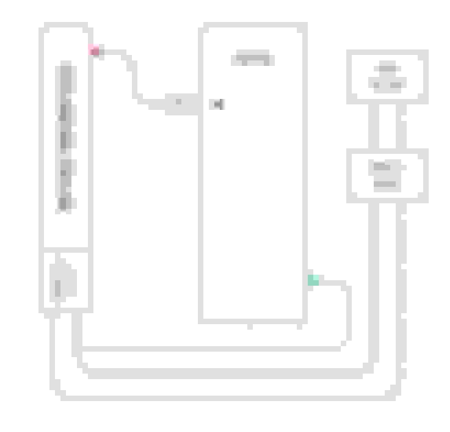
Moroso was kind enough to provide us with a photograph of a PCV air / oil separator properly installed on an otherwise stock '90-'05 Miata engine:
Here's a schematic of what this looks like:
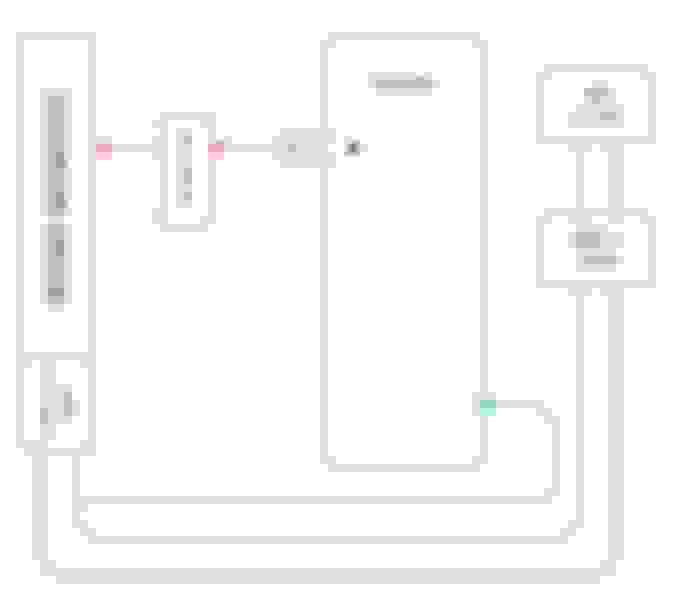
Moving up to a turbocharged engine using a MAF/AFM-based ECU (this is increasingly rare for us), here's what that should look like:
Note that in the above diagram, the sole function of the separator is to deal with occasional blowback out of the non-PCV side of the valve cover (reversing the flow of the blue lines), under conditions of extreme load (eg: leaking PCV valve, or extreme blowby). We want to prevent that vapor from getting into the intercooler where it will condense out to liquid.
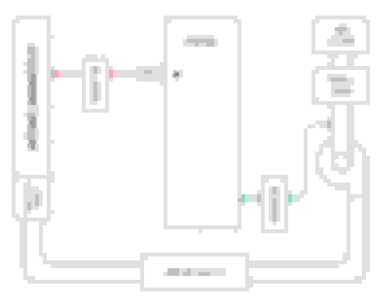
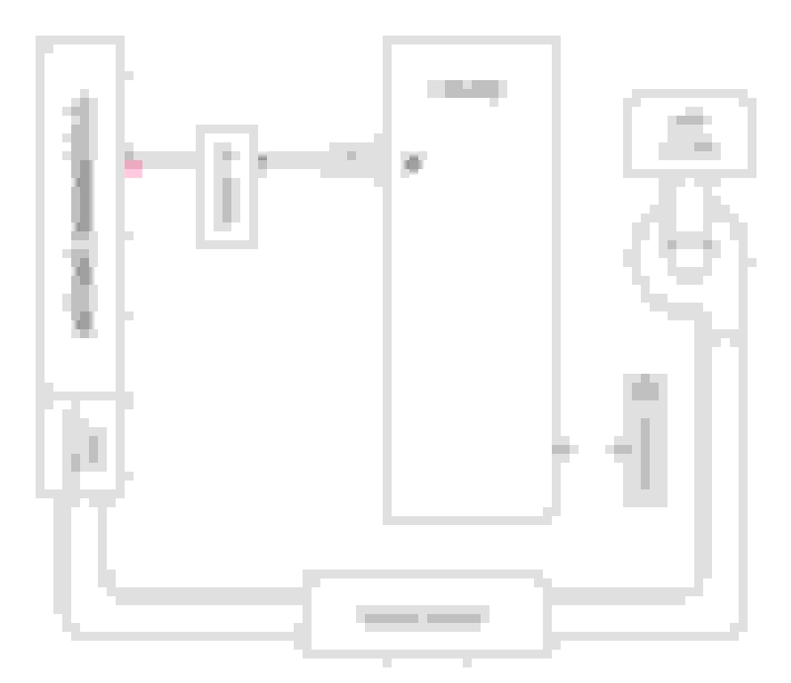
Finally, the most typical application for our purposes, a turbocharged engine using a MAP-based ECU, where we are not required to connect the non-PCV side to the intake tract:
(Note that I have illustrated a breather tank here, which is a worst-case scenario. Many engines of this configuration will be fine with a small filter fitted directly to the valve cover, as shown in the photo of my engine earlier.)
A note on PCV valves: The OEM unit shipped with the '90-'05 Miata engines is known to perform poorly in forced-induction engines. The old-school solution is to replace it with the unit from a 323 GTX engine (factory turbocharged) which has identical dimensions and drops right into place. Mazda part number E-301-13-890A, Motorcraft equivalent EV-146. While it's possible that a better solution exists, I personally never needed anything more than this. Example: https://www.prioritymazdaparts.com/o...lve-e30113890a
In extreme applications, such as turbocharged engines operated at continuous high power on the track, it's entirely possible for the amount of blowby produced to overwhelm the capacity of the system pictured above. Remember that under boost, the PCV valve is (or should be) fully closed, so there is only one port which is effectively available to vent it. Evidence of this condition occurring is often found in the form of the oil dipstick having been pushed upwards out of its tube.
In such cases, it may be beneficial to eliminate the PCV valve (sealing the port on the intake manifold to which it connected) and instead use this the orifice for a second breather vent:
This configuration effectively* doubles the capacity of the engine to exhale blowby when operating at continuous high load. Obviously the "breathing in clean air" function at low to mid-throttle, which is made possible by the action of the PCV valve, is lost. (There is no longer a pressure differential created by the intake manifold across the valve cover.) As such, this design is inadvisable on street-driven cars with "normal" oil change intervals.
* = Actually, more than doubles. See the link below under "2:" in the valve cover notes.
I have shown two breather tanks above. If a sufficiently large breather tank with multiple inlet ports is used, then both hoses may go to a single tank.
A NOTE ON THE VALVE COVER ITSELF:
These ports, to which the PCV and breather attach, do not simply open into the hollow interior of the valve cover. Cast into the underside of the cover itself are a series of baffled chambers, not unlike the baffling in an external air / oil separator. Thus:
1: Simply drilling a new hole into the valve cover, which is outside of the baffled region, will result in a lot more oil coming out of that port.
2: The design of the baffling, and the passages which feed it, is fairly restrictive. There is already a thread which explores this in some detail, with proposed modifications to increase ventilation for cars which require it: https://www.miataturbo.net/engine-pe...ication-54742/
Last edited by Joe Perez; Mar 13, 2019 at 06:21 AM.
I believe it is important to emphasize that in a FI setup the exhaust side is most likely flowing quite a bit of gas out. Significantly more than the PCV ever does. As such, proper treatment of the undersized passeges inside the VC baffle chambers as well as potentially increasing the INNER diameter of the vent is warranted. I have measured crankcase pressures as low as 1 psi gauge and correlated them with turbo drain issues.
What about a check valve on the fresh air line? I put a gm air pump check valve on all my small blocks fresh air lines. No more oil in my air cleaners. They are high flow, and readily close with any pressure, even small amounts. They're also designed to be mounted on the air tubes and are exhaust fume and heat resistant. If you have a smog equipped GM they're free, but they're only like $20 new at NAPA.
Could you dispense the pcv valve entirely and run the entire system on a vacuum pump with a air oil separator, smokey yunick style?
The PCV operates to allow some crankcase gasses to be ingested during times of low load and moderate to high vacuum through a metered orifice. As the throttle position is changed to wide open the available vacuum drops to near zero and rises to positive pressure on a forced induction engine, closing the valve. Meanwhile, the blow by entering the crankcase past the piston rings is dramatically increased and must exit somewhere. This will either be through your gaskets and seals or through the crankcase vent in the exhaust side of the valve cover. On an engine making three times as much power as stock there will be approximately three times as much blow-by. If you do not provide an adequate pathway then your engine will leak profusely out of the weakest seals. Additionally, the vapors exiting the exhaust side valve cover port will be traveling at such a high velocity they will carry copious amounts of oil with them, filling a catch can and emptying the engine in a very short amount of time.
The single exhaust side port and its accompanying gallery in the top of the valve cover is designed for the blow by of a roughly 120 horsepower engine. You wouldn't run stock exhaust at two or three times stock horsepower for the same reason you can't leave this unaltered without consequence.
There are several reasons I do not want oil vapor from the crankcase entering my intake manifold. Oil vapor, when burned, creates carbon deposits on pistons, valves, and combustion chamber walls. These carbon deposits become hot spots which promote detonation. Additionally, oil vapor has a much lower octane value and will promote pre-ignition of the inlet charge when present.
Enlarging the ports and hoses significantly and taking both ports to a vented collection can has caused nearly zero oil to end up out of the engine at the end of a track day at over 300 horsepower.
If you are smitten with the idea of 1961 California smog control laws and really want to run a PCV valve on the cold side of your valve cover I highly recommend adding two large outlets and hoses to the hot side and a significant enlargement of the openings and baffling within the hot side of the valve cover as a Band-Aid for not doing it the right way. Remember, the PCV valve only works when your engine is at idle or low load.
And no, you cannot run a check valve because the PCV is a metered orifice. Otherwise you will have an unmetered vacuum leak.
If you are smitten with the idea of 1961 California smog control laws and really want to run a PCV valve on the cold side of your valve cover I highly recommend adding two large outlets and hoses to the hot side and a significant enlargement of the openings and baffling within the hot side of the valve cover as a Band-Aid for not doing it the right way. Remember, the PCV valve only works when your engine is at idle or low load.
I can certainly see the benefit to adding a second breather vent on the non-PCV side of the engine for engines operated at high boost for long periods.
But even in a track car, you're going to be off-boost for quite a bit of the time, such as when braking. Having very little first-hand experience in this situation, I would argue that retaining the PCV valve (with a catch tank between it and the manifold) can only be beneficial, as it will retain the function of drawing clean air into the clean and venting out the combustion gasses.
The combustion gases are constantly replenishing the crankcase at a tremendous rate, especially on a forced-induction track car. Stagnation will never be an issue.
On a naturally-aspirated commuter car a PCV valve makes perfect sense. On a forced induction track or dual duty car that sees 70% track I would not have one for an additional point of boost leak failure or the other reasons mentioned previously.
I�ll throw dons setup up here for reference. Kept the POV, ran 3/8� line from the exhaust side to the rear breather can, and pcv to a recirc can next to it.
I used radium�s Universal dual catch can kit and made a simple bracket off the fuse box bracket. Order with a straight, 45, and 90 degree fitting.
Thanks for taking the time to write all this up, Joe.
One thing I don't see listed on these configurations is a check-valve between the intake manifold and the catch-can. Without a check valve, wouldn't you blow boost into the catch-can in positive manifold pressure?
One thing I don't see listed on these configurations is a check-valve between the intake manifold and the catch-can. Without a check valve, wouldn't you blow boost into the catch-can in positive manifold pressure?
I can't think of any situation where that would be relevant.
If you are running a PCV valve, then you must use a non-vented air / oil separator between the intake manifold and the PCV valve. The PCV valve acts as a check valve.
If you are not running a PCV valve, and have a vented breather can attached to the former PCV port on the valve cover, then the PCV port on the intake manifold must be blocked off.
I think the relevant situation is when even the 323 PCV valve is not adequate to prevent back-flow during boost. It was once, and is, common to combine a check valve in series with the PVC (can be stock) on either side of, or even without, the separator can.
I think a point that has been made, but not emphasized, is that when using no PCV, one should change the oil in a turbocharged engine at 3K mile intervals. Some would say 3K either way. This could be discussed further, including possible change intervals increased after TBN analysis. EDIT: Valid comments in other threads. Does lack of PVC really make any difference to life of oil? Is it there only to lower emissions, or also to enhance oil life / efficacy? My NON-PVC Blackstone report was virtually identical to the WITH-PVC report.
In your last (after edit 1... I don't know what things looked like before edit 1) you show both cover ports as exists going to separate separators. If a large separator is used, then both ports can go to a single separator (As Six does today). A minimal footnote.
Lastly, a FYI that eliminating PVC will result in foul odors could be added. Does a proper VTA separator help with that? IDK, I have not installed it yet. Just blocked off PVC and still have the little hot side filter dripping oil on manifold at this point in time.
Last edited by DNMakinson; Mar 12, 2019 at 12:31 PM.
Reason: Look for emboldened EDIT
A check valve right after the PCV valve is good practice in all applications.
It is also worth mentioning that if you use the car on track, you should consider capping the PCV/intake side breather entirely, or be prepared to constantly drain catch cans connected to that side (like every few laps). For all 94-00 motors, you can and should simply block the PCV valve and run a breather from the driver's side only. For VVT motors, a much more complex air/oil separation system is sometimes required.
And no, you cannot run a check valve because the PCV is a metered orifice. Otherwise you will have an unmetered vacuum leak.
I use a check valve in combination with a PCV. The check valve goes between my intake pre-carb on the fresh air line, only allowing fresh air into the engine, never allowing crankcase pressure to vent into my carb. The GM air pump check valve is huge, though. Fits nice and snug in a breather SBC valve cover grommet, not sure how much work it'd take to adapt to a Miata.
I seem to recall reading something about the cold side PCV port puking out oil out on sustained high-G left hand turns and that this (for some reason) was not the problem on the hot side opening. Is there any validity to this?
I've done two experiments with PCV system so far:
My 2017 setup: Cold Side: GTX valve in OEM configuration Hot Side: internal baffle holes opened to 1/2". -8 AN plumbing out to a catch can and then plumbing to pre-turbo piping to draw a vacuum. Results: Blowby collected was minimal and usually just frothy nastiness that would separate into mostly water.
My 2018 setup: Cold Side: Plugged with a PEX barbed plug. Hot Side: Internal baffle holes opened to 1/2". -8 AN plumbing out to a catch can and can was VTA Results: Collected almost all oil and would fill the catch can in ~15 minutes in track conditions.
Car has now been swapped to a 1.8L VVT w/11.5:1 compression and will be naturally aspirated for a couple years. Currently, I'm trying to answer the question, "What is my 2019 setup?"
Seems like 2 approaches to cold side. Six says open things up enough to slow flow speed (possibly baffle changes also) will fix oil puke on that side on track. Andrew says nothing helps.
Present thought for my 220 street, 175 track WHP; is to block cold side and use VTA separator on hot side until blowby gets bad enough to lift dipstick, if ever. Kind of a poor man’s, low power combination that is not included in the first post.
EDIT: I see that is basically Andrew’s recommendation above.
Joe, feel free to purge any of my dribble once discussion is over.
Cold Side: Plugged with a PEX barbed plug. Hot Side: Internal baffle holes opened to 1/2". -8 AN plumbing out to a catch can and can was VTA Results: Collected almost all oil and would fill the catch can in ~15 minutes in track conditions.
Either the motor was unhealthy, or all the internal mods just made things worse. Rover has a plugged PCV valve and a filter on the hotside without a catch can, because there's not enough oil coming from the driver's side to warrant one.
I guess i'll have to re-think my catch-can strategy. Original plan was to remove PCV fitting and enlarge both sides of VC to accept a welded -10an bung. Both sides plumbed into a 2port catch-can that vents to atmosphere. Cap intake manifold.
Rover has a plugged PCV valve and a filter on the hotside without a catch can, because there's not enough oil coming from the driver's side to warrant one.
That is what I have presently on my 1999. The little filter, mounted directly on the port, is saturated with oil and occasionally drips.


 28
28