When you click on links to various merchants on this site and make a purchase, this can result in this site earning a commission. Affiliate programs and affiliations include, but are not limited to, the eBay Partner Network.
We used to use a thin SLS manifold in SAE for that exact reason. Idled like ****, but you can get an extra 20% airflow past the restrictor by sucking air through the plastic
I was acting as more of a grad student advisor at the time, so just made em the intake and they were happy with it. When I was involved as an undergrad at the actual competitions it was on the electric side so can't say for certain.
Good to have sparked thi conversation.
I've asked you because we also use a CR10-max in our workshop, and have now a customer which is taking in consideration a set of ITB and 3d printed manifold.
The issue that now we're trying to solve are:
1) did nylon or polycarb or ASA resist well to gasoline fumes?
2) in which way could we avoid the problem of plastic porosity? We tought about print with a lot of "shell thickness" and maybe coat the 3d print with some kind of paint but we arent aware of a good solution at this time.
1). Cf nylon is great with gasoline with no issues withstanding it for long periods of time. And although it's already great, the fact that the injectors rest in the head minimize exposure as a whole.
2). The fact that cf nylon is printed at such a high temp (~250*C=480*F), it bonds very densely, and eliminates porosity. It is a very solid material. I more so use a lot of shell thickness for the purpose of overbuilding the f*ck out of it so it doesn't break. If you wish to go a step further, there is a sintering process you can use on cf nylon to really fuse the part together, but in my experience it is not necessary. I have been able to hold a constant 20kPa vacuum in the manifold with no issues, and that is the absolute lowest you'd ever get to with ITBs (on decel in gear at high rpm).
If you are going to print it, cf nylon is the best stuff you can get. And it is perfectly sufficient, even having very slight flex properties from nylon which definitely helps with loads.
wow, indeed very interesting. Did you notice some wear of nozzles with fiber nylon?
Yes, i know exposure is minimum, however is always necessary to take in account.
We've not took in account nylon wich however seem a good choice, we've started with PC.
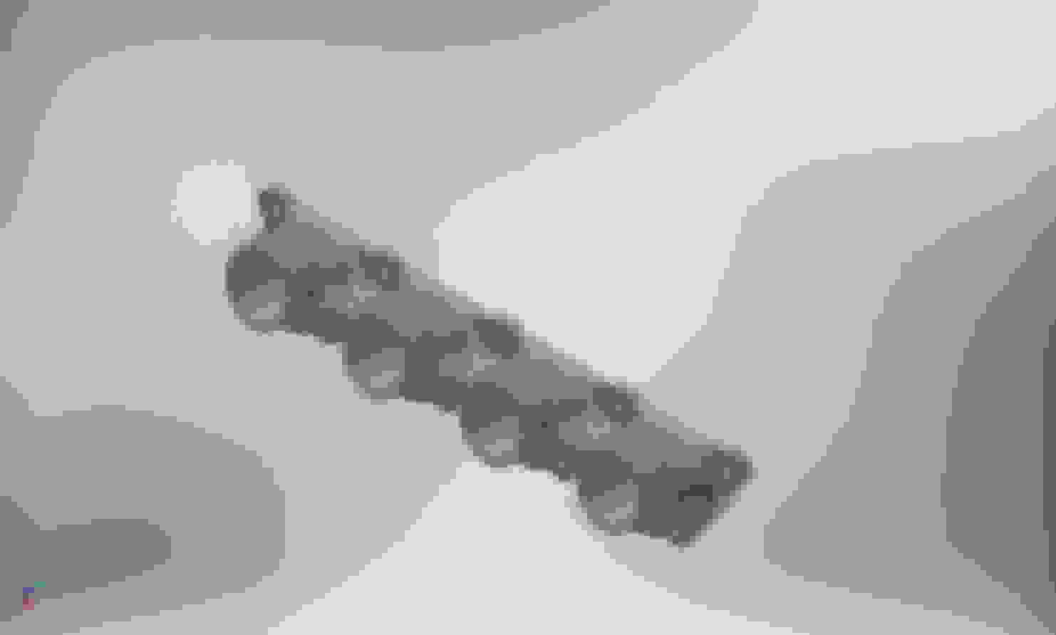
in the previous photo you can see the concept study for mating 4x 42mm suzuki ITB to a BP05 head from a 1994 1.8 miata, w/ short silicone hose joint.
Have you some suggestion or hints about design?
What id of ITB did you use? we lend to 45mm, no more (maybe 42mm) in order to get fast passing flow (-the customer wants a "mid torque" engine).
Cf nylon requires the hotend hardened nozzle upgrade and after that it prints fine and doesn't wear down.
Your design is great, I see no problem. Very simple and tried and true.
The R6 ITB sizing I currently run is 42mm, which is fine except for the fact that there is a little flange clamp that brings it down from the 42mm dia circle to a smaller R6 port. I don't feel as comfortable using the hose connection method like the gsxr because there is not much material on the R6 side for the hose to clamp down on. So I am stuck using their little adapters which resultantly hinder the engines power from a regular 42mm dia circle.
In response to that I bought the R1 throttles, which not only have a 45mm dia bore, but the R1 port has the same cross sectional area as a Miata port. So my previous bottleneck with the R6 should be no more. Maybe eventually I will use the hose method, but for now the flange makes life easier.
I actually have one comment on the design. When you have the hose connecting runners go to the Miata adapter, make sure the wall isn't too thick to where that hose won't fit around it. But you also have to make it somewhat thick for strength.
Glad to see more people going down that path; have attempted that as well on my 1.6, abandoned it mid-way due to engine swap and boost. One additional thing to consider; brace the ITBs on the block and do not let their full weight hanging on the printed bit. It sure can last in elevated temperatures, but it WILL creep under heat and weight.
A brace is something I did heavily consider. While there's not one on I am tempted to do it even after the 200 lb weight FEA I did just for ***** and giggles lol
This is a wise observation.
Also on motorbikes, the ITB are sustained because they're attached to airbox - which is usually bracketed on the chassis-.
And on motorbikes you does not have any engine shaking.
Yeah, but did you consider properties in elevated temperatures on that FEA?
Creep is what gets them.
At least equally as important for any FEA on an additive process is that without some rather significant chemistry/batch mechanical testing work for each given print condition, properly setting up your material properties for the simulation is essentially impossible. Virgin nylon might be strong enough, but printed parts are highly anisotropic. Now, if you're hanging 20 lbs off the thing and you FEA the geometry with bulk nylon properties and are happy with your stresses at 200 lbs then I'd put my money on it not snapping, but HarryB is absolutley correct in that chop fiber filled nylon is certainly not known for being resistant to creep deformation. Maybe if you printed it in CF-PEEK or Vespel/Polyimide I'd be a bit more confident, but at that point you may as well just get it CNC'd out of aluminum, the geometry isn't that crazy �\_(ツ)_/�.
Those are some great points yeah. I should definitely check temps and look into more info on how carbon nylon deals with creep. Think I'll check it out this weekend
So far I've been using abs as my material in sims because I haven't loaded a specific one for cf nylon. My reasoning was just to try and give it as many setbacks as possible and if it still ends up holding then it would warrant a good amount of reassurance. The load I gave (200lb) was another extreme condition when in reality it is only about 4 lbs.
I will check temperature and creep though, great points.


 0
0