
My Planet Audio Amp Died....

Thread Starter
Elite Member
iTrader: (16)
Joined: Aug 2007
Posts: 9,406
Total Cats: 559
From: Houston, TX
So I have an old Planet Audio TT2150 150W x2 max power amp. I bought it used for $20 about 3 years ago. It's worked well until recently. I notice I have no bass. Eventually I get around to checking and sure enough, the fuse is blown. It only had a 10 amp fuse cause I don't exactly work it that hard, so I put another 10 in. I have bass again. So I drive it maybe 20 minutes and no more bass. Fuse again. So I put another fuse in, this time a 15. Now the speaker hums very loudly, slowly moves up and down maxing out the speaker and sounds terrible like a witch screaming or something. Then blows another fuse.
Amp's torn apart on my desk right now. I've fixed a few amps before. Once I found a broken bridge, once a broken resistor, once a component had a piece of solder that fell and welded itself shorted. Usually simple stuff. So far, no such luck. I do notice one area of the board appears heat damaged possibly. Also, someone added two resistors to the amp. No idea why, but it's definitely the work of someone that can't solder. However it's worked for 3 years flawlessly up until now.
I've checked all the capacitors so far and they're all fine and measure what they should. Checked all the diodes and they are all checking fine. Trying to check the transistors right now. Exactly how would I do this? What should I check next?
Pictures uploading.
EDIT: Pics
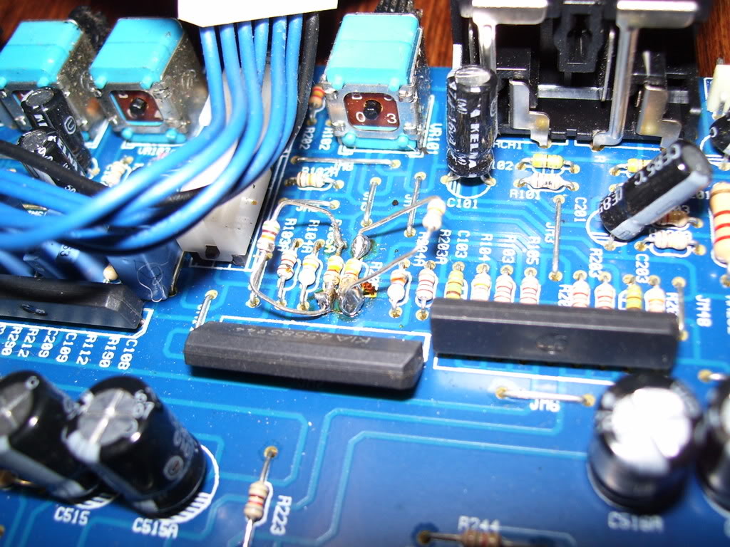
This pic shows the added resistors. No idea why these were added, but it worked fine for 3 years.
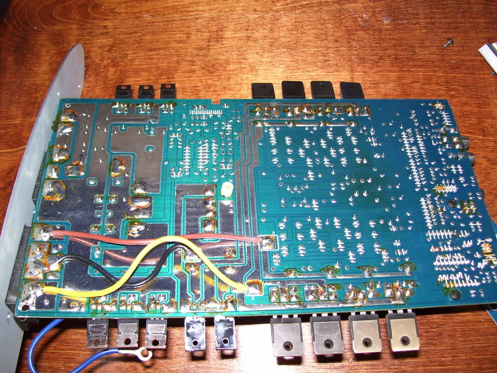
Here's a pic of the board. From center, to the right a bit you'll see the discolored area I think has overheated.
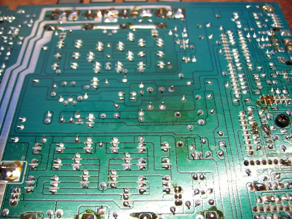
Zoomed in on discolored area
Amp's torn apart on my desk right now. I've fixed a few amps before. Once I found a broken bridge, once a broken resistor, once a component had a piece of solder that fell and welded itself shorted. Usually simple stuff. So far, no such luck. I do notice one area of the board appears heat damaged possibly. Also, someone added two resistors to the amp. No idea why, but it's definitely the work of someone that can't solder. However it's worked for 3 years flawlessly up until now.
I've checked all the capacitors so far and they're all fine and measure what they should. Checked all the diodes and they are all checking fine. Trying to check the transistors right now. Exactly how would I do this? What should I check next?
Pictures uploading.
EDIT: Pics
This pic shows the added resistors. No idea why these were added, but it worked fine for 3 years.
Here's a pic of the board. From center, to the right a bit you'll see the discolored area I think has overheated.
Zoomed in on discolored area
Last edited by patsmx5; Oct 10, 2008 at 09:53 PM.
Reply
 0
0

0


Thread Starter
Elite Member
iTrader: (16)
Joined: Aug 2007
Posts: 9,406
Total Cats: 559
From: Houston, TX
Uh, no. I'm a cheap SOB. I haven't gotten my $20 worth out of this one yet...
Ok, I suspect two transistors. They're the only two that don't have metal on the backs of them. They did not have a mica insulator on them and they just mounted directly against the aluminum body of the amp. I'm ASSuming the base is the middle pin with the dot on it. Is this a valid assumption? All the transistors on the amp the middle pin is base and they all have a dot here. From reading, it seems there should be high resistance between the collector and emmiter. This is true for every transistor on the am except these two. They show a short between emitter and collector. Perhaps I need to remove them from the circuit for testing? Or have I found the problem? I'll upload a pic of said transistors in a sec.
EDIT: Pic
The two in question are centered in pic. One on the left is a FMG225. Searched for a datasheet on it and got nothing.
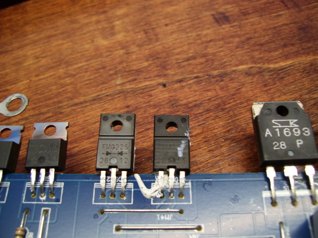
Reply
0
0
Reply
0
0

Thread
Thread Starter
Forum
Replies
Last Post
Rudes333
Miata parts for sale/trade
17
Nov 5, 2015 01:16 PM


