94-95 & 96-97 MAF Delete Discussion
#41
Boost Czar


iTrader: (62)
Join Date: May 2005
Location: Chantilly, VA
Posts: 79,501
Total Cats: 4,080
#3 is the intake sensor....it shouldn't be a shared signal. it's simply the input for the ECU to read the AIT from.
Take voltmeter from the #3 pin on the harness and (94-95 2P Red/Black) (96-97 3K Red/Black) and you'll have no resistance. it goes straight from the harness to the ECU.
Since the MAF only has two functions, temp and airflow, you can easily assume the red/green wire is the MAF signal. Black/Blue & Black/Lt Green are always grounds, all years. White/Red is always +12v, all years.
READ SON.
#42
Wow I must be retarded, no joke but I am not understanding anything.
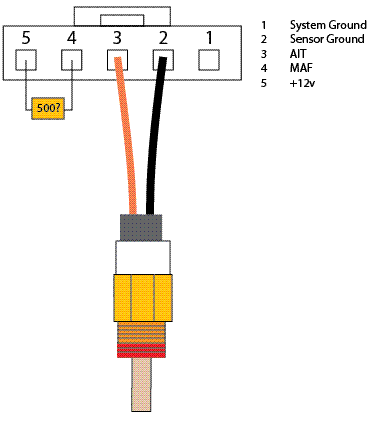
So you want me to try either A. Connect AIT to pins (3 or 5) to pin 4 or B. Jump those same pins with a resistor?
AIT needs 5v or 12v? I am confused by the post you quoted and the mspnp website.
So you want me to try either A. Connect AIT to pins (3 or 5) to pin 4 or B. Jump those same pins with a resistor?
AIT needs 5v or 12v? I am confused by the post you quoted and the mspnp website.
(color codes for '97)
1) Blk/Lt Grn = Chassis Ground
2) Blk/Blu = Sensor Ground
3) Red/Blk = 5V
4) Red/Wh = Signal
5) Wh/Red = 12V (KL15/IGN SWITCHED)
1) Blk/Lt Grn = Chassis Ground
2) Blk/Blu = Sensor Ground
3) Red/Blk = 5V
4) Red/Wh = Signal
5) Wh/Red = 12V (KL15/IGN SWITCHED)
Last edited by Saml01; 11-21-2007 at 11:50 AM.
#43
Elite Member
Thread Starter
iTrader: (3)
Join Date: May 2006
Location: Houston, TX
Posts: 2,895
Total Cats: 0
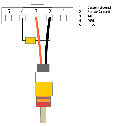
Pin 3 -> resistor -> GND (1 or 2) = AIT
Pin 5 -> big resistor (no clue what resistance, but since it's replacing a heating element it needs to be a minimum of 1/4 watt, possibly more). -> Pin 4 = MAF
Pin 5 -> big resistor (no clue what resistance, but since it's replacing a heating element it needs to be a minimum of 1/4 watt, possibly more). -> Pin 4 = MAF
#44
Boost Czar


iTrader: (62)
Join Date: May 2005
Location: Chantilly, VA
Posts: 79,501
Total Cats: 4,080
this is the best i can do.
remember I know nothing about electronics....all im trying to do it give the ecu something to work with....it usually sees a 0-5v signal that changes as the heated element cools. Or at least trick the ecu that something is there...


remember I know nothing about electronics....all im trying to do it give the ecu something to work with....it usually sees a 0-5v signal that changes as the heated element cools. Or at least trick the ecu that something is there...


#46
Boost Czar


iTrader: (62)
Join Date: May 2005
Location: Chantilly, VA
Posts: 79,501
Total Cats: 4,080
there's no 5v................................................ .................................................. .................................................. .................................................. .................................................. .................................................. .................................................. .................................................. ..................................
#48
Elite Member
Thread Starter
iTrader: (3)
Join Date: May 2006
Location: Houston, TX
Posts: 2,895
Total Cats: 0
there's no 5v................................................ .................................................. .................................................. .................................................. .................................................. .................................................. .................................................. .................................................. ..................................
*edit* the AIT is essentially a pull down resistor from 5V
#50
Pin 3 had 5V on it with the key turned on... I measured it. I believe it's a basic voltage divider on that 5V line which goes through the AIT (resistor) to ground. As the AIT varies in resistance the voltage across the divider (bias resistor) in the ecu changes and that is what the ECU sees at it's processor.
*edit* the AIT is essentially a pull down resistor from 5V
*edit* the AIT is essentially a pull down resistor from 5V
If the ECU gives 5 volts thats going to be shared with the MS, whats gonna happen?
I knew I wasnt crazy.

#55
Elite Member
Thread Starter
iTrader: (3)
Join Date: May 2006
Location: Houston, TX
Posts: 2,895
Total Cats: 0
Agreed. I think the safest thing to try first, as you said, is to ground the MAF pin through a resistor. I'll see if I can stick some jumper wires into the connector over the weekend and see what voltage the ECU is seeing on pin 4 while the car is running. That + resistance from pin 4 to chassis GND should give us enough to estimate an appropriate resistor if my understanding is correct.
#56
Someone on one of my other forums brings up a good point.
If I was going to share the AIT with the stock ECU and the MS, what of the bias resistor thats also present in the Mazda ECU?
As for his second part, arkmage you think you can measure that resistance?
Cut the bias resistors and you can share the sensors between the ECU and the MS.
For the MAF part, the basics behind the velocity sensor is that the ECU keeps the resistor at a constant temperature (verified by resistance), it then measures the current needed to keep the sensor at that temperature. The current needed is a measure of mass flow rate, the velocity is actually calculated by using the mass flow rate divided by the air density (found from temp).
You should measure the resistance of the MAF at its heated temp (140-160C) and try to find a resistor close to that.
As for his second part, arkmage you think you can measure that resistance?
#57
Elite Member
Thread Starter
iTrader: (3)
Join Date: May 2006
Location: Houston, TX
Posts: 2,895
Total Cats: 0
That's not what the pin is kicking out. It's spitting out a voltage which I believe is 0-5V. It's not actually measuring the current on the heater. If it were then there would not need to be a seperate pin and the 12V line wouldn't be shared with the fuel pump relay and a few other things.
#58
Boost Czar


iTrader: (62)
Join Date: May 2005
Location: Chantilly, VA
Posts: 79,501
Total Cats: 4,080
whoever posted that was a retard.
I'll say it again. The ECU provides a +12v current into the heated element. it heats up and sends varies the resistance on the output.
when air passes over it, it cools and decreases the resitance.
the end.
here's some reading
rx7 AFM to hotwire MAF:
http://howto.globalvicinity.com/gv_w...=120&co=1&vi=1
Originally Posted by wikipedia
This is achieved by heating a wire with an electric current that is suspended in the engine’s air stream, not unlike a toaster wire. The wire's temperature increases with the wire’s electrical resistance, which limits electrical current flowing through the circuit. When air flows past the wire, the wire cools decreasing its resistance, which in turn allows more current to flow through the circuit. As more current flows, the wire’s temperature increases until the resistance reaches equilibrium again. The amount of current required to maintain the wire’s electrical resistance is directly proportional to the mass of air flowing past the wire. The integrated electronic circuit converts the measurement of current into a voltage signal which is sent to the ECU.
If air density increases due to a pressure or temperature change, but the air volume remains constant, the denser air will remove more heat from the wire indicating a higher mass airflow. Unlike the vane meter's paddle sensing element, the hot wire responds directly to air density. This sensor's capabilities are well suited to support the gasoline combustion process which fundamentally responds to air mass, not air volume. (See stoichiometric.)
If air density increases due to a pressure or temperature change, but the air volume remains constant, the denser air will remove more heat from the wire indicating a higher mass airflow. Unlike the vane meter's paddle sensing element, the hot wire responds directly to air density. This sensor's capabilities are well suited to support the gasoline combustion process which fundamentally responds to air mass, not air volume. (See stoichiometric.)
#59
whoever posted that was a retard.
I'll say it again. The ECU provides a +12v current into the heated element. it heats up and sends varies the resistance on the output.
when air passes over it, it cools and decreases the resitance.
the end.
here's some reading
rx7 AFM to hotwire MAF:
http://howto.globalvicinity.com/gv_w...=120&co=1&vi=1
I'll say it again. The ECU provides a +12v current into the heated element. it heats up and sends varies the resistance on the output.
when air passes over it, it cools and decreases the resitance.
the end.
here's some reading
rx7 AFM to hotwire MAF:
http://howto.globalvicinity.com/gv_w...=120&co=1&vi=1
Seems pretty accurate and straight forward.
And what of the bias resistors?
#60
I calculated my stock bias resistor for my coolant sensor, only reason i have an accurate coolant reading. I don't think this is all that hard. I don't think the stock ECU with know it's head from it's *** if you stick a resistor in there that is 1k ohms hi or lo. All this bullshitting around can be solved by just shoving some crap in the pins to see what happens.


