Notices
MEGAsquirt A place to collectively sort out this megasquirt gizmo

94 DIYPNP V1.5B Questions about AC

Thread Tools
 
Search this Thread
 
Old Aug 8, 2013 | 09:44 AM
  #21  
Braineack's Avatar
Boost Czar
iTrader: (62)
 
Joined: May 2005
Posts: 80,552
Total Cats: 4,368
From: Chantilly, VA
Default

my picture was to be used as illustrative purposes only.

r14 is not installed, it needs to be installed now. I didn't notice that before.
Old Aug 8, 2013 | 09:55 AM
  #22  
ScottyP3821's Avatar
Thread Starter
Senior Member
iTrader: (2)
 
Joined: Jun 2012
Posts: 1,153
Total Cats: 50
From: Texas
Default

Ok so I want to make sure I got this straight. Install 2.2k resistor on r14.

Jumper

1J&4s>Input 1 OUT
Input 1 IN> PA0
PE1>Relay 1 IN
Relay 1 OUT> 1Q

Is this correct?
Old Aug 8, 2013 | 10:41 AM
  #23  
Braineack's Avatar
Boost Czar
iTrader: (62)
 
Joined: May 2005
Posts: 80,552
Total Cats: 4,368
From: Chantilly, VA
Default

no, that's not correct.

I'll repeat myself:

1Q > Input1 IN
Input1 OUT > PE1
PA0 > Relay 1 IN
Relay 1 Out > 1J&4S
Old Aug 8, 2013 | 10:43 AM
  #24  
Braineack's Avatar
Boost Czar
iTrader: (62)
 
Joined: May 2005
Posts: 80,552
Total Cats: 4,368
From: Chantilly, VA
Default

Originally Posted by Braineack
no, that's not correct.

I'll repeat myself:

1Q > Input1 IN
Input1 OUT > PE1
PA0 > Relay 1 IN
Relay 1 Out > 1J&4S
Hey braineack, did you mean:

1Q > Relay1 IN
Relay1 OUT > PE1
PA0 > Input 1 IN
Input 1 Out > 1J&4S

????
Old Aug 8, 2013 | 10:43 AM
  #25  
Braineack's Avatar
Boost Czar
iTrader: (62)
 
Joined: May 2005
Posts: 80,552
Total Cats: 4,368
From: Chantilly, VA
Default

Originally Posted by Braineack
Hey braineack, did you mean:

1Q > Relay1 IN
Relay1 OUT > PE1
PA0 > Input 1 IN
Input 1 Out > 1J&4S

????
no, i did not. i usually don't put outputs on input circuits. However, i do tend to put outputs on relays and inputs on inputs.
Old Aug 8, 2013 | 11:34 AM
  #26  
ScottyP3821's Avatar
Thread Starter
Senior Member
iTrader: (2)
 
Joined: Jun 2012
Posts: 1,153
Total Cats: 50
From: Texas
Default

Originally Posted by Braineack
no, i did not. i usually don't put outputs on input circuits. However, i do tend to put outputs on relays and inputs on inputs.

So the picture of how I wired it is fine just add the resistor?
Old Aug 8, 2013 | 11:43 AM
  #27  
Braineack's Avatar
Boost Czar
iTrader: (62)
 
Joined: May 2005
Posts: 80,552
Total Cats: 4,368
From: Chantilly, VA
Default

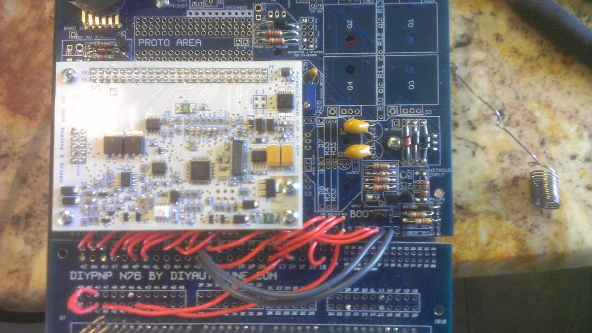
my picture is probably wrong. go by my werds.


but yeah. when it's wired to activate the a/c without the MS in the mix, r14 is removed. Since you're sending it back to the ECU first now, you need that pull up.

I'm not exactly sure what circuit DIY used for the inputs, but I'm pretty sure that's a pull-up. you could steal one from an unused circuit on the board if you are desperate. I'm pretty sure r14 is 2.2K, but a 1K might work... I'd need to see pics of the top of the board to see what resistors might be unused and able to work. Probably there's a 2.2K reistor on the high side driver circuit that you aren't using.
Old Aug 8, 2013 | 12:03 PM
  #28  
ScottyP3821's Avatar
Thread Starter
Senior Member
iTrader: (2)
 
Joined: Jun 2012
Posts: 1,153
Total Cats: 50
From: Texas
Default

How about I pull r 38. It is part of the nitrous driver and I don't like nitrous. the resistor is colored red red red gold and to my knowledge that would be an ideal 2.2 k candidate.
Old Aug 8, 2013 | 12:06 PM
  #29  
Braineack's Avatar
Boost Czar
iTrader: (62)
 
Joined: May 2005
Posts: 80,552
Total Cats: 4,368
From: Chantilly, VA
Default

i think that's the one im talking about.
Old Aug 8, 2013 | 12:15 PM
  #30  
ScottyP3821's Avatar
Thread Starter
Senior Member
iTrader: (2)
 
Joined: Jun 2012
Posts: 1,153
Total Cats: 50
From: Texas
Default

Ok so I'm going to move the r38 2.2k to r14 and leave my jumper the way I have them and I should be good to go plug into the car and start without frying anything?
Old Aug 8, 2013 | 12:27 PM
  #31  
Braineack's Avatar
Boost Czar
iTrader: (62)
 
Joined: May 2005
Posts: 80,552
Total Cats: 4,368
From: Chantilly, VA
Default

that's the plan.
Old Aug 8, 2013 | 12:29 PM
  #32  
ScottyP3821's Avatar
Thread Starter
Senior Member
iTrader: (2)
 
Joined: Jun 2012
Posts: 1,153
Total Cats: 50
From: Texas
Default


Here's what I got I removed r38 and moved it r14. Just wanted to post a pic for reference.
Attached Thumbnails 94 DIYPNP V1.5B Questions about AC-image.jpg  
Old Aug 8, 2013 | 01:04 PM
  #33  
Braineack's Avatar
Boost Czar
iTrader: (62)
 
Joined: May 2005
Posts: 80,552
Total Cats: 4,368
From: Chantilly, VA
Default

while you are in there, move the two wires going to 4C and 4D to SG from GND
Old Aug 8, 2013 | 01:07 PM
  #34  
ScottyP3821's Avatar
Thread Starter
Senior Member
iTrader: (2)
 
Joined: Jun 2012
Posts: 1,153
Total Cats: 50
From: Texas
Default

Ok will this add any other features.
Old Aug 8, 2013 | 01:13 PM
  #35  
Braineack's Avatar
Boost Czar
iTrader: (62)
 
Joined: May 2005
Posts: 80,552
Total Cats: 4,368
From: Chantilly, VA
Default

Originally Posted by ScottyP3821
Ok will this add any other features.
it will move the sensor grounds to the sensor ground plane.
Old Aug 8, 2013 | 02:56 PM
  #36  
ScottyP3821's Avatar
Thread Starter
Senior Member
iTrader: (2)
 
Joined: Jun 2012
Posts: 1,153
Total Cats: 50
From: Texas
Default

Originally Posted by Braineack
it will move the sensor grounds to the sensor ground plane.
Car starts and runs like **** now with a bouncing idle before it dies. Where do I go from here.
Old Aug 8, 2013 | 03:08 PM
  #37  
ScottyP3821's Avatar
Thread Starter
Senior Member
iTrader: (2)
 
Joined: Jun 2012
Posts: 1,153
Total Cats: 50
From: Texas
Default

Ok accidentally forgot to plug the map in my bad but still no AC engagement.

Edit

Msq found here

https://www.miataturbo.net/megasquir...-my-msq-74292/
Old Aug 8, 2013 | 03:10 PM
  #38  
Braineack's Avatar
Boost Czar
iTrader: (62)
 
Joined: May 2005
Posts: 80,552
Total Cats: 4,368
From: Chantilly, VA
Default

and you've made sure to setup the software for the correct inputs (PE1) and outputs (PA0).
Old Aug 8, 2013 | 03:50 PM
  #39  
ScottyP3821's Avatar
Thread Starter
Senior Member
iTrader: (2)
 
Joined: Jun 2012
Posts: 1,153
Total Cats: 50
From: Texas
Default

Got it to kick on now I guess I need to play with the idle and closed loop settings.
Old Aug 8, 2013 | 05:24 PM
  #40  
ScottyP3821's Avatar
Thread Starter
Senior Member
iTrader: (2)
 
Joined: Jun 2012
Posts: 1,153
Total Cats: 50
From: Texas
Default

This is such a pain in the ***. Do I have to use Closed Loop because PWM Warm up is easy and I suck at closed loop.


All times are GMT -4. The time now is 12:42 PM.