99+ MS-II install issues
 12-26-2007, 05:09 PM
#41
Elite Member

Thread Starter
iTrader: (3)
Join Date: Aug 2006
Location: San Diego, CA
Posts: 3,047
Total Cats: 12
She Runs!!
Oh yeah. It's my birthday, have a party. :-)
A little story telling, questions at the end.
I spent like hours sitting next to the car, trying to perfect the idle..... Realizing that I had such a wide range of values where it worked that I had no idea when I was making it better. Then Arga sent me some files, an older version of the code he said worked better. Somehow I thought it started faster - it starts well but takes a while to do it (syncing late?) though this morning, oddly, it didn't start so fast.
It was very cool taking off from a stop sign, deciding it felt underpowered at the stop-and-go type clutch feathering, and running into a parking lot to work on it, and five minutes later having the car better-than-stock at that one simple task.
The speedometer works, and so does the cruise control - but I still have the OEM ecu plugged in (it's back behind everything else). I'm going to pull it, and if it works, the link piggy, o2 clamp, o2 simulator, and the old knock sense come out (actually, I could run the two in parallel till I get the settings right.)
Now I'm going to make another thread for the weird tuning issues, try to keep this segmented, easier to follow.

Reply
 0
0

0
12-28-2007, 02:04 AM
#42
Elite Member
Thread Starter
iTrader: (3)
Join Date: Aug 2006
Location: San Diego, CA
Posts: 3,047
Total Cats: 12
Just an FYI - figuring it wasn't doing anything anyway, I unpluged the OEM ECU today. She ran fine. Speedo works, cruise control works. The only thing missing is EGR. Oh, and I think it took the CEL with it. :-)
Once I get the tach working, I'd say I'm back up to normal (you know, minus the 5k stumble and the no boost, etc. ha!).
Basically, buying the connectors for the OEM ecu was a total waste of good money. Anyone looking to do a late model car, buy the mopar altenator controler with the money you would have spend on connectors. I can turn my fans on and off as I like, same with VICS, and after a bit of messing with it, the idle even seems to be working nice.
-Abe.
Reply
0
0
01-06-2008, 12:55 AM
#43
Elite Member
Thread Starter
iTrader: (3)
Join Date: Aug 2006
Location: San Diego, CA
Posts: 3,047
Total Cats: 12
Ok, after a whole day of messing around, soldering, unsoldering, etc... And getting traces just like yours first for the crank sensor (it would "stick" every 4th tooth) and then for the cam sensor (didn't happen till I fixed the crank) I got it all working *perfect*.
I get the same signal before and after my simple input circuit. Right now I have ~880 ohms to the sensor, and a 10k pull up on the back side of that to +5V - that intersection between the two resistors feeds my 1970's 2n2222A.
The issue was: Sensor position. The crank is speced ~0.025"-0.050" or so, and it was very nearly 50. I thought it was too close, but just for the heck of it, I moved it into ~25 mils. Bingo, it's been flawless since.
Then the cam sensor was weird, and since it's not adjustable, I didn't know what to do. I moved it radially in and out from the sensor as far as I could, no effect. Then I loosened the bolt, pulled it away from the valve cover... and bingo, great signal. The "sticking" went away. So I put a washer under the bolt, an o-ring under the sensor, and now all my signals are perfect.
Basically, the thing you forgot to check is the input of the circuit. It's not your VR circuit (I don't think you want to use a VR anyway), it's the sensor itself. Why the sensor got weird, I don't know. Might be a sign of something bigger around the horizon.
Anyway. Now you can see that my signal inputs match exactly my signal outputs (to the MS-II ecu, one read on the 40pin DIP, one read at TSEL). The signals look awesome, too.
My issue now is: I still don't sync! And I'm out of ideas about why. I thought it was a problem with the coils, but no, they work perfect (recently switched to COP) when testing. And things don't improve if I unplug them.
Unless it has something to do with my pulling the fuel pump relay (and I doubt the current to that is being measured) I'm at a loss.
I tried it with b15 and arga's file on my old chip, and b17 and a cleanly generated file on the new chip. Neither one is working - I get "sync" for a moment once every few revs.
I wish there were a way to log the pulses the computer counts, when does it see a falling edge?
pics:
Sticking Crank Sensor:

Sticking Cam Sensor:

Fix for cam sensor:

Trouble with too small a pull up resistor on Cam:

Note how it can't quite sync all that current, and the tops are wavy. This was with 1700 ohms total between sensor and 5V. At 11,000 ohms, it's fine.
What the sensor outputs look like, with 11k of pullup to 5V:

Finnally, this is what my car is doing:

The smaller traces are the inputs to the ECU, the larger ones are the raw signals.
I would really like some help with why my car won't sync! Could it be because of noise? My guess is it has to do with the different spacing of the pulses. My cam pulses are NOT co-incident with the crank pulses
Higher res/additional pictures available at:
http://abefm.smugmug.com/gallery/4117931#240164291
I get the same signal before and after my simple input circuit. Right now I have ~880 ohms to the sensor, and a 10k pull up on the back side of that to +5V - that intersection between the two resistors feeds my 1970's 2n2222A.
The issue was: Sensor position. The crank is speced ~0.025"-0.050" or so, and it was very nearly 50. I thought it was too close, but just for the heck of it, I moved it into ~25 mils. Bingo, it's been flawless since.
Then the cam sensor was weird, and since it's not adjustable, I didn't know what to do. I moved it radially in and out from the sensor as far as I could, no effect. Then I loosened the bolt, pulled it away from the valve cover... and bingo, great signal. The "sticking" went away. So I put a washer under the bolt, an o-ring under the sensor, and now all my signals are perfect.
Basically, the thing you forgot to check is the input of the circuit. It's not your VR circuit (I don't think you want to use a VR anyway), it's the sensor itself. Why the sensor got weird, I don't know. Might be a sign of something bigger around the horizon.
Anyway. Now you can see that my signal inputs match exactly my signal outputs (to the MS-II ecu, one read on the 40pin DIP, one read at TSEL). The signals look awesome, too.
My issue now is: I still don't sync! And I'm out of ideas about why. I thought it was a problem with the coils, but no, they work perfect (recently switched to COP) when testing. And things don't improve if I unplug them.
Unless it has something to do with my pulling the fuel pump relay (and I doubt the current to that is being measured) I'm at a loss.
I tried it with b15 and arga's file on my old chip, and b17 and a cleanly generated file on the new chip. Neither one is working - I get "sync" for a moment once every few revs.
I wish there were a way to log the pulses the computer counts, when does it see a falling edge?
pics:
Sticking Crank Sensor:
Sticking Cam Sensor:
Fix for cam sensor:
Trouble with too small a pull up resistor on Cam:
Note how it can't quite sync all that current, and the tops are wavy. This was with 1700 ohms total between sensor and 5V. At 11,000 ohms, it's fine.
What the sensor outputs look like, with 11k of pullup to 5V:
Finnally, this is what my car is doing:
The smaller traces are the inputs to the ECU, the larger ones are the raw signals.
I would really like some help with why my car won't sync! Could it be because of noise? My guess is it has to do with the different spacing of the pulses. My cam pulses are NOT co-incident with the crank pulses
Higher res/additional pictures available at:
http://abefm.smugmug.com/gallery/4117931#240164291
Reply
0
0
01-06-2008, 01:17 AM
#44
Man. You know a $75 CAS shipped to your door would have given you so many more hours of drive time while you figure out these issues... :(
What is the world could be different between your car or MS build and Argas.
I can offer some encouragement though. That cam sensor fix is pretty darn clever. I had to replace my crank sensor, used a feeler gauge it space it within factory specs. The previous owner had broken it and epoxied it out of line. I think he was trying to adjust the timing that way, similar to what FM does with their bolt on timing wheel.
Reply
0
0
01-06-2008, 02:32 AM
#45
Elite Member
Thread Starter
iTrader: (3)
Join Date: Aug 2006
Location: San Diego, CA
Posts: 3,047
Total Cats: 12
From the MS forums:
And here is the the data for the M2 (NB) Miata, 1999-2005.
The numbers are crank degrees relative to the #1 TDCC (negative being before and positive after)
Crank signal edges in one engine cycle ( engine cycle = 720 crank degrees), 16 edges total:
falling edge at -80 ( == 640 )
raising edge at -77 ( == 643 )
falling edge at -10 ( == 710)
raising edge at -7 ( == 713 )
falling edge at 100
raising edge at 103
falling edge at 170
raising edge at 173
falling edge at 280
raising edge at 283
falling edge at 350
raising edge at 353
falling edge at 460
raising edge at 463
falling edge at 530
raising edge at 533
Cam sync signal edges in one engine cycle, 6 edges total:
falling edge at 37
raising edge at 57
falling edge at 377
raising edge at 397
falling edge at 421
raising edge at 441
Jim
_________________
Reply
0
0
01-14-2008, 02:44 AM
#49
Elite Member
Thread Starter
iTrader: (3)
Join Date: Aug 2006
Location: San Diego, CA
Posts: 3,047
Total Cats: 12

Injectors all installed. With some of the carbon canister and EGR stuff removed and the VICS stuff redone, it's a whole new engine bay. Not to mention the Failin' Miata fuel rail.
'Course, I didn't have the right o-ring grommet things, so I made some:

The final ones were a bit better. Straighter. The diameter is a bit small... Not sure I should sweat it.
Finally, for comparison, yes the Evo 550cc injectors (from a 2005, supposedly) were under $100 and fit great!

Really, though, I just wanted to use the phrase Failin' Miata. All their **** breaks, what the hell?
Reply
0
0
01-15-2008, 03:35 AM
#50
Elite Member
Thread Starter
iTrader: (3)
Join Date: Aug 2006
Location: San Diego, CA
Posts: 3,047
Total Cats: 12
So, with these peak-and-hold injectors... weirdness happens. If you follow the instructions in the megamanual, you will quickly end up with 0% current setting. Why it still runs, I don't know. I have a guess that the opening time is too long.
Anyway, everything was hunkey dory, got an awesome idle (well, after a huge scare getting the motor up to 230+ degrees, because my table for the water temp sensor wasn't right - this was all at idle, who knows, I guess it's ok though)..... But at ~4k, things go dead lean. Super weird lean. I had the VE table looking like a step function.
It would make the SMALLEST of differnces, if any. Then, I put the current to 10 % and it gets way better. So now it's at 25% which I'm sure it too much. Need to figure all this out, it probably will invovle more work than I want and an oscilliscope.
Luckily, I have a supply of 50, 25, 20, 15 and yes: 1 milliohm resistors. :-)
So the moral of the story, if the numbers seem unreasonable, go with your gut - the manual isn't always right.
Now I get to do a compression test, then maybe this weekend I'll tackle trying to get the injector numbers figured out. If I was smart I'd pull-and-flow test them, they seem to click weird in test mode.
Reply
0
0
01-16-2008, 03:08 PM
#51
Elite Member
Thread Starter
iTrader: (3)
Join Date: Aug 2006
Location: San Diego, CA
Posts: 3,047
Total Cats: 12
Ok, am I going crazy here? The limited advice on the forums seems like total guesswork. I've got a very simple circuit for an input, and I MIGHT be having noise issues.
They are telling me to take out my transistor inverting follower and use their opto-in.

But I see them as functionally the same, as long as I keep my voltages below, oh, 3000 volts. And the bottom circuit is already built.
I guess I could do it like this:

But it is actually any better than just adding a bigger cap to the circuit I've got?
I think I'm just missing one tooth every great once in a while and the software sucks at dealing with it.
<edit> Maybe I should swap the green line "jumper" for a ~470 ohm resistor, just to give that cap a fighting chance.
They are telling me to take out my transistor inverting follower and use their opto-in.
But I see them as functionally the same, as long as I keep my voltages below, oh, 3000 volts. And the bottom circuit is already built.
I guess I could do it like this:
But it is actually any better than just adding a bigger cap to the circuit I've got?
I think I'm just missing one tooth every great once in a while and the software sucks at dealing with it.
<edit> Maybe I should swap the green line "jumper" for a ~470 ohm resistor, just to give that cap a fighting chance.
Last edited by AbeFM; 01-16-2008 at 04:12 PM.
Reply
0
0
01-17-2008, 12:24 PM
#52
Elite Member
Thread Starter
iTrader: (3)
Join Date: Aug 2006
Location: San Diego, CA
Posts: 3,047
Total Cats: 12
Well, progress, of a sort.
Since I was dead tired last night, the only* work I did on the MS was to put on bigger capacitors. I put them on, the motor started right up, so I went to bed. On the way to work, I thought everything was awesome, while it was cold. Less stumbling at low RPM.
Then things warmed up and it went to total ****, barely could rev past the 5k rough spot.
So, an order of magnitude bigger caps doesn't work. Guess I'll try smaller. :-) I should get it on the scope and look at my traces. Maybe the sensors chatter somehow, though if they are true hall effect I don't see how they would.
*I lied. Someone mentioned grounding and power not being good enough, so I ran two 14 guage grounds to the block in addition to the OEM harness grounds, AND I added a 14 guage +12V switched directly to the main relay block.
Reply
0
0
01-17-2008, 01:23 PM
#53
Junior Member

Join Date: Aug 2006
Location: Ridgecrest, Ca
Posts: 306
Total Cats: 0
I liked that input circuit they listed on Pat's thread at the MS2E dev board where they run the crank signal "backwards" into the LED on the opto circuit then run 5v into the other end. I liked the first one from the Neon better than the second. It should work nicely stand-alone or parallel. I'd try it but mine is working well and I really don't want to screw with it.
When your stumbling at revs over 5k, are you loosing sync?
When your stumbling at revs over 5k, are you loosing sync?
Reply
0
0
01-17-2008, 04:48 PM
#54
Elite Member
Thread Starter
iTrader: (3)
Join Date: Aug 2006
Location: San Diego, CA
Posts: 3,047
Total Cats: 12
Wow! Yes! It's working!
Ok, first off: Yeah, using the grounding of the circuit to complete the circuit on the opto is pretty cool. Definitely the "right" way. That guy is on crack telling me not to. :-) I think I drew it up more or less right there. Too much capacitance.
So, the news: I went ahead and installed 0.001uf (1nf) resistor, and BINGO! Still started, and drove fine! I had *one* hiccup on the way home (15 min trip), and one on the way back. Not sure if there's some correlation (time, temperature, etc). But better than 20+ per trip, sometimes 5 or six in ten seconds.
Now, the weird news. I had put the cam sensor back to the stock location, and I *thought* it was starting slower. When I got out of my house from lunch (having completed one trip on the set up and changing nothing), it wouldn't start. No sync.
Well, I remembered last time moving the cam sensor helped, so I did (wiggling the wires doesn't seem to do anything), and it started up (not a particularly fast sync, but not a slow one).
So, in short, my circuits are these:

But I'll have to double check the resistance values, and the caps are 1nf.
Overall, I'm pretty happy. A day or two of messing with it, getting a feeling for it, and I'll be adding boost. Time to look at redoing my tables, I guess. :-) I'll play with different sized shims on the cam sensor. I have a feeling what helps it start is bad at runtime, but that's not based on any actual facts. :-)
Frank - please post what you're using right now, exact values, etc.
Ok, first off: Yeah, using the grounding of the circuit to complete the circuit on the opto is pretty cool. Definitely the "right" way. That guy is on crack telling me not to. :-) I think I drew it up more or less right there. Too much capacitance.
So, the news: I went ahead and installed 0.001uf (1nf) resistor, and BINGO! Still started, and drove fine! I had *one* hiccup on the way home (15 min trip), and one on the way back. Not sure if there's some correlation (time, temperature, etc). But better than 20+ per trip, sometimes 5 or six in ten seconds.
Now, the weird news. I had put the cam sensor back to the stock location, and I *thought* it was starting slower. When I got out of my house from lunch (having completed one trip on the set up and changing nothing), it wouldn't start. No sync.
Well, I remembered last time moving the cam sensor helped, so I did (wiggling the wires doesn't seem to do anything), and it started up (not a particularly fast sync, but not a slow one).
So, in short, my circuits are these:
But I'll have to double check the resistance values, and the caps are 1nf.
Overall, I'm pretty happy. A day or two of messing with it, getting a feeling for it, and I'll be adding boost. Time to look at redoing my tables, I guess. :-) I'll play with different sized shims on the cam sensor. I have a feeling what helps it start is bad at runtime, but that's not based on any actual facts. :-)
Frank - please post what you're using right now, exact values, etc.
Reply
0
0
01-17-2008, 11:42 PM
#55
Junior Member
Join Date: Aug 2006
Location: Ridgecrest, Ca
Posts: 306
Total Cats: 0
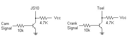
I'm running the same thing I sent you a few weeks ago. Both cam and crank circuits are the same.
No pull-up on the line to the sensor (stock ECU handles that)
signal input -> 10k resistor -> transistor base
Vcc -> 4.7k-> emitter
collector -> ground
the line to TSEL (J10 for the cam) is pulled between the emitter and the 4.7k
No pull-up on the line to the sensor (stock ECU handles that)
signal input -> 10k resistor -> transistor base
Vcc -> 4.7k-> emitter
collector -> ground
the line to TSEL (J10 for the cam) is pulled between the emitter and the 4.7k
Reply
0
0
01-18-2008, 02:55 AM
#56
Elite Member
Thread Starter
iTrader: (3)
Join Date: Aug 2006
Location: San Diego, CA
Posts: 3,047
Total Cats: 12
It's really strange you can get away without any capacitance. There's a chance the caps in the OEM ECU are doing this for you, but I'm pretty impressed. Then again, without another transistor to buffer out the noise, maybe I'm more susceptable to it.
I should give that a shot.
Thinking about the code, it doesnt' care on the leading/trailing edge of the cam pulse (so inverting it doesn't matter) since they happen well within the window of one crank tooth and the next, irrerspective of which edge you look at.
Maybe I'll go back to that part of your set up. And maybe I'll try to figure out if I want the risingor falling edge, though last time I messed with it I found the one I was using worked best.
Reply
0
0
01-18-2008, 01:06 PM
#59
Elite Member
Thread Starter
iTrader: (3)
Join Date: Aug 2006
Location: San Diego, CA
Posts: 3,047
Total Cats: 12
Ha. Yeah. Well, thanks for rubbing that in my face, Rev. :-P Here I was all prepared to tell you about the only issue with my car, when you ask me about the idle. :-)
To get that out of the way, the idle is significantly worse with the idle hooked up than not. It's noisey, way noisey. It used to work when I had it on ~70hz, but it was far and away the loudest sound in the whole car below ~1800 rpm. So I moved it up to 160 or something (you only get two choices for freq in MS-IIx). It got queiter, and I never really got it tuned. Then I switched off PID and it's been idling well, except that it idles at like 550 rpm when headlights and fans and heater are on.
They changed the way the controller works in b17, and I can't get it working nice like I had it in the earlier version. It's just much slower, it STARTS to work when you max the Proportional Gain, but to get it right I think I'd have to be at like 210% gain, not 100% (the max). Arga, are you running beta 17 or 18 yet?
Anyway, the real news:
Remember how I said my car magically wouldn't start? Well, did the same thing this morning, but I couldn't fix it. I put the cam shim back in, didn't help. It seems like it's not firing? I was checking timing yesterday (took the ground lead, put in a length of wire with like 30-50 wraps, put it around my timinglight pick up, and then let it see ground) which worked (though I'm not sure how valid this is, timing wise). Anyway, put it all back, I thought things were cool... But now no start. Oddly, sometimes it says synced. Most of the time, actually.
Here's the weird part: RPM are reporting way low, and dropping. Instead of 250, typically what I see, it's 180 and drops to 50 pretty quick.
So, something is way wrong. I guess I need a scope. Something is wrong, period, but I don't know what, since Arga has no filter caps at all.
Reply
0
0


