
A better Spark Out circuit.


Reply
 0
0

0


Reply
0
0

Junior Member
Joined: Jul 2005
Posts: 273
Total Cats: 1
From: Hillsborough, NC
FYI, with this setup, if you accidentally load in a config with SPARK OUTPUT INVERTED set to NO, it'll get your ignitor reaaally hot, and the car will run like crap. But no apparent damage to the car.
I haven't experienced this myself.... But it's actually comforting to know that it won't necessarily blow your coil pack.
Even so... anybody who uses this setup should put a BIG DISCLAIMER on any MSQ's that they share publicly!
I haven't experienced this myself.... But it's actually comforting to know that it won't necessarily blow your coil pack.
Even so... anybody who uses this setup should put a BIG DISCLAIMER on any MSQ's that they share publicly!
Last edited by JustinHoMi; Jun 19, 2009 at 11:01 AM.
Reply
0
0
FYI, with this setup, if you accidentally load in a config with SPARK OUTPUT INVERTED set to NO, it'll get your ignitor reaaally hot, and the car will run like crap. But no apparent damage to the car.
I haven't experienced this myself.... But it's actually comforting to know that it won't necessarily blow your coil pack.
Even so... anybody who uses this setup should put a BIG DISCLAIMER on any MSQ's that they share publicly!
I haven't experienced this myself.... But it's actually comforting to know that it won't necessarily blow your coil pack.
Even so... anybody who uses this setup should put a BIG DISCLAIMER on any MSQ's that they share publicly!
So in short whatever setup you're using having the output wrong will damage something!
Reply
0
0

Well, I decided to swap over my spark output to this circuit when I moved my MS from my 93 to my 96. In the process I blew one of my igniter/coil assemblies. I'm not blaming the new circuit. Joe was very clear to change Spark Out Inverted to YES and I did just that on the base map I started up with (a modified PNP map). I was having some problems with my idle and while sitting on the side of the road with a dying laptop battery, I decided to load up my old map from my 93 and see how it did. In the process I forgot the change the Spark Out Inverted setting on the old map and apprantly it blew one of my ignitor/coil assemblies. Limped it home and checked and I was only running on cylinders 1/4. Disconnected my MS outputs and returned spark and fuel control to my stock ECU. Still only running on 1/4. Checked continuity and voltage to the 2/3 coil and they look fine so it's pretty much gotta be the ignitor/coil. I may go ahead and upgrade to COPs or PlanetMiata has a used coilpack for $75. We'll see.
It's funny, one other time I stupidly reloaded the firmware in my 93 (with the old circuit) without disconnecting my ignitor and nothing blew. I guess my luck finally ran out.
All that said, do make sure you have your Spark Output Inverted set correctly in Megatune and be careful when using various old maps or maps from other folks.
Reply
0
0

Elite Member
Joined: Mar 2008
Posts: 2,054
Total Cats: 14
From: Enschede, NL
Got excellent feedback from DIY. Now need to find time to sort this further...
Originally Posted by DIYAutotune.com
We are aware of that circuit, but we haven't tested it for ourselves.
However, if you want to try putting it on an MSPNP, here's what you
would do.
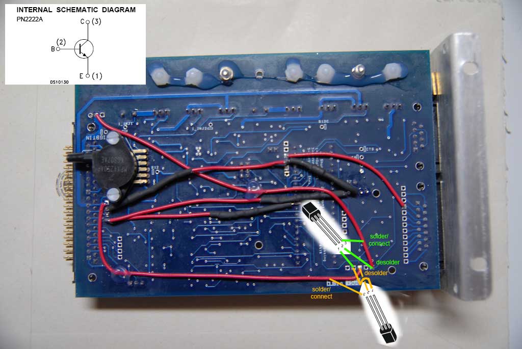
1. Desolder the jumpers from PAD1 and PAD3.
2. Take a PN2222(A) transistor and connect it as follows:
* Emitter pin to ground (PAD4)
* Base pin to PAD1
* Collector pin to the jumper that previously connected to PAD1
3. Take a second PN2222(A) and repeat step 2, substituting PAD3 for PAD1.
4. Disconnect the coils and power up the MSPNP.
5. In MegaTune, change the Spark Output Inverted setting to YES and burn
to ECU.
6. You can now connect the coils.
Again, we haven't tested this particular mod version for ourselves in
house (although we did experiment with another mod Joe mentions that is
a bit harder to use), but this should duplicate what Joe is doing
without too much fuss. The pull up resistor Joe mentions is already on
the MSPNP adapter card and stays in place.
Thanks,
Matt Cramer
DIYAutotune.com Technical Support
However, if you want to try putting it on an MSPNP, here's what you
would do.
1. Desolder the jumpers from PAD1 and PAD3.
2. Take a PN2222(A) transistor and connect it as follows:
* Emitter pin to ground (PAD4)
* Base pin to PAD1
* Collector pin to the jumper that previously connected to PAD1
3. Take a second PN2222(A) and repeat step 2, substituting PAD3 for PAD1.
4. Disconnect the coils and power up the MSPNP.
5. In MegaTune, change the Spark Output Inverted setting to YES and burn
to ECU.
6. You can now connect the coils.
Again, we haven't tested this particular mod version for ourselves in
house (although we did experiment with another mod Joe mentions that is
a bit harder to use), but this should duplicate what Joe is doing
without too much fuss. The pull up resistor Joe mentions is already on
the MSPNP adapter card and stays in place.
Thanks,
Matt Cramer
DIYAutotune.com Technical Support
Reply
0
0
Thread Starter


Joined: Sep 2005
Posts: 34,414
Total Cats: 7,531
From: Chicago. (The less-murder part.)
Reply
0
0
Supporting Vendor

Joined: Sep 2006
Posts: 2,332
Total Cats: 67
This:
Well, more or less - it wasn't driven off the CPU output pin itself, but through a more complex circuit.
We could achieve this by using a PNP transistor on the CPU output pin (PNPs have the opposite control polarity of NPNs)
Reply
0
0
Thread Starter
Joined: Sep 2005
Posts: 34,414
Total Cats: 7,531
From: Chicago. (The less-murder part.)
Sadly, I see that your prediction of someone frying their ignition by loading an old .MSQ has come true...
Reply
0
0
Joe,
Forgive my "I haven't picked up a textbook in a decade" thought here, but couldn't we just jump the resistor/diode, and swap in a PNP, taking the signal off the other leg?
You might have to dig around the layout a bit, but that should give you the inversion you were looking for, without adding parts?
Reply
0
0
 I forgot to update the software!
Reply
0
0

Junior Member
Joined: Jul 2005
Posts: 273
Total Cats: 1
From: Hillsborough, NC
Joe,
Forgive my "I haven't picked up a textbook in a decade" thought here, but couldn't we just jump the resistor/diode, and swap in a PNP, taking the signal off the other leg?
You might have to dig around the layout a bit, but that should give you the inversion you were looking for, without adding parts?
Forgive my "I haven't picked up a textbook in a decade" thought here, but couldn't we just jump the resistor/diode, and swap in a PNP, taking the signal off the other leg?
You might have to dig around the layout a bit, but that should give you the inversion you were looking for, without adding parts?
Reply
0
0


