
A better Spark Out circuit.

Supporting Vendor

Joined: Sep 2006
Posts: 2,332
Total Cats: 67
hang on, so are we saying that DIYPNP has the output inverted and therefore doesn't need to have the coils unplugged when burning - so why do DIYAutotune still recommend it in their online docs?
http://www.diyautotune.com/diypnp/ap...3-16b6-mt.html
http://www.diyautotune.com/diypnp/ap...3-16b6-mt.html
Reply
 0
0

0


Thread Starter

Joined: Sep 2005
Posts: 34,416
Total Cats: 7,531
From: Chicago. (The less-murder part.)
So, gslender, to summarize:
The way DIY has the DIYPnP set up, the ignition outputs are being driven directly by the CPU's output pins. That configuration is therefore inherently non-inverting, and is functionally identical to my "improved" circuit, which is technically double-inverting, which is the same as non-inverting.
So, because these circuits are non-inverting, you must select "Inverted" in the software. (I'd love to know who came up with that nomenclature in the software.)
And you should now have any problems with either spark-at-poweron or fried coils during reflash.

Reply
0
0
I should have said 'errtime. But yeah, that was back in the Kingof1337
days of MS.
IIRC it didn't work well, I had major spark cutout issues with low boost or something., I think i still ended up damaging my ignitor too. When I moved to the DIY suggest output using the LED and a pull-up it was much improved.
days of MS.
IIRC it didn't work well, I had major spark cutout issues with low boost or something., I think i still ended up damaging my ignitor too. When I moved to the DIY suggest output using the LED and a pull-up it was much improved.
Reply
0
0
Thread Starter
Joined: Sep 2005
Posts: 34,416
Total Cats: 7,531
From: Chicago. (The less-murder part.)
Years ago, I did some measurements on a stock 1.6, looking at the voltage profile of the trigger signal, and it sure as heck appeared as though it was drawing a lot of current into a capacative load.
Now that I do have a DC current probe, I may go and re-test.
But what I'm getting at is that perhaps the MS2 CPU pins simply can't supply enough current to make the stock '90-'93 igniter happy. This would be consistent with our need to run relatively small values of R in the pullups on MS1-style output drivers.
edit: It appears that it was in this very thread:
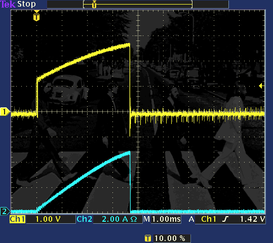
Yellow is the voltage into the igniter. Blue is coil primary current.
Reply
0
0

Junior Member
Joined: Dec 2008
Posts: 53
Total Cats: 0
Just read through this thread, hoping to see some reference to MS1 V2.2. Is this mod possible (required?) on the MS1 V2.2? If so.. anybody care to help out a super newb on the mods required? I had planned to make the modifications in this thread:
https://www.miataturbo.net/showthrea...highlight=v2.2
PS: I will be using MSnS-E (latest firmware..?)
https://www.miataturbo.net/showthrea...highlight=v2.2
PS: I will be using MSnS-E (latest firmware..?)
Reply
0
0

Elite Member
Joined: Jul 2005
Posts: 6,420
Total Cats: 84
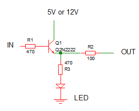
I can't believe I never showed this circuit, which I've used in a few AEM's for several years now (minus the LED). It accomplishes the same thing as Joe's 2-transistor circuit, with the advantage that the pullup current can be made very high by reducing the 100 ohm resistor value, and the maximum you can run is determined by the transistor gain and current capability, as opposed to being determined by the pullup resistor in Joe's circuit. With some coils the 100ohm resistor in my circuit can be zero. Using a pullup resistor to source current for the coils has the disadvantage of having to always sink current from the VCC supply.
The AEM has weedy output current capability in "pull up to dwell" mode, incapable of driving the 99/00 coils to full current. This may be why some have seen big gains with the Toyota COPs with the AEM. The popular Toy COPs don't need as much current and the AEM can drive them to full current. In contrast, the circuit below is needed for the AEM to drive 99/00 coils to max current.
I've noticed that various coils need varying amounts of drive current and the voltage when they're driven to max current also varies. Overdriving them may or may not have negative effects. So the 100 ohm resistor in my schematic may have to change depending on what coils you are driving.
Last edited by JasonC SBB; Feb 23, 2012 at 12:00 AM.
Reply
1
1

Elite Member
Joined: Jul 2005
Posts: 6,420
Total Cats: 84
I'll be the analog circuit guru for mt.net, free consultations, as long as you keep posting humorous cat pics.
Or maybe help my friend scare an arsehole neighbor into not being an arsehole.
When I first saw your circuit long ago, I somehow thought you were trying to solve a different problem...
Now if only the folks over at msextra would believe me when I talk about signals, circuits, filters and control systems...
Reply
0
0

I can't believe I never showed this circuit, which I've used in a few AEM's for several years now (minus the LED). It accomplishes the same thing as Joe's 2-transistor circuit, with the advantage that the pullup current can be made very high by reducing the 100 ohm resistor value, and the maximum you can run is determined by the transistor gain and current capability, as opposed to being determined by the pullup resistor in Joe's circuit. With some coils the 100ohm resistor in my circuit can be zero. Using a pullup resistor to source current for the coils has the disadvantage of having to always sink current from the VCC supply.
The AEM has weedy output current capability in "pull up to dwell" mode, incapable of driving the 99/00 coils to full current. This may be why some have seen big gains with the Toyota COPs with the AEM. The popular Toy COPs don't need as much current and the AEM can drive them to full current. In contrast, the circuit below is needed for the AEM to drive 99/00 coils to max current.
I've noticed that various coils need varying amounts of drive current and the voltage when they're driven to max current also varies. Overdriving them may or may not have negative effects. So the 100 ohm resistor in my schematic may have to change depending on what coils you are driving.
The AEM has weedy output current capability in "pull up to dwell" mode, incapable of driving the 99/00 coils to full current. This may be why some have seen big gains with the Toyota COPs with the AEM. The popular Toy COPs don't need as much current and the AEM can drive them to full current. In contrast, the circuit below is needed for the AEM to drive 99/00 coils to max current.
I've noticed that various coils need varying amounts of drive current and the voltage when they're driven to max current also varies. Overdriving them may or may not have negative effects. So the 100 ohm resistor in my schematic may have to change depending on what coils you are driving.
If so, would this work for coils with +12v triggers?
-Raj
Reply
0
0

Elite Member
Joined: Jul 2005
Posts: 6,420
Total Cats: 84
Yes
No. What coils require 12V triggers?
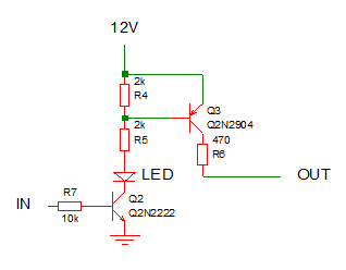
In any case here's a sparkout circuit that will do 12V and will have more drive capability (determined by the 470 ohm resistor) than Joe's original.
If so, would this work for coils with +12v triggers?
-Raj
-Raj
In any case here's a sparkout circuit that will do 12V and will have more drive capability (determined by the 470 ohm resistor) than Joe's original.
Reply
0
0
Ok if I were to implement this, I would need ?pnp? tansistors and would 2907's work?
And just to make sure I have this straight, these basically replace q6 and q8 correct?

If I were to leave q6/q8 in place this is how I would do it, does it look right?
Disconnect r26/r29 and run 470ohm resistor from squirt/accel to 2907
2907 collector goes to 5v on proto
470ohm from "transited spark outputs" to base of led, and also 100ohms to db37 pins
It would be great if someone could clarify! Thanks
Reply
0
0


