A better Spark Out circuit.
#162
Boost Pope


Thread Starter
iTrader: (8)
Join Date: Sep 2005
Location: Chicago. (The less-murder part.)
Posts: 33,026
Total Cats: 6,592
Telling them apart is easy. Look at the direction of the arrow on the emitter relative to the base. NPN = Not Pointing iN, whereas PNP = Pointing iN.
You could use anything in the 2n3904 / 2n2222 / etc range.
And just to make sure I have this straight, these basically replace q6 and q8 correct?
Also, Jason, I'm not sure how this circuit will "have more drive capability (...) than Joe's original." You can reduce the pullup resistor in mine to 100 or even 50 ohms and it'll work the same way. The 3904 will pass 200ma, and the 2222 will pass 1A.
Actually, I do see one thing about the single-transistor circuit you have shown which is less optimal than the dual-transistor circuit I drew originally. In your version, the current going out to the ignitor passes through the transistor, so the voltage on the output will inherently drop by an amount equal to VCE, in addition to drop across the resistor. On mine, the output current does not pass through a transistor, so it'll always be equal to VCC.
#163
Oh, ok thanks for the clarification! I've got pnp's left over from your mod. My ms2 can run my cops with 100 ohm pullup on your circuit whereas the ms1 couldn't with getting tons of resets. I wanted to try Jasons method and see if I still had resets...
Just curious, isn't Jason's output able to pull more current from 5v on proto then your's and stock setup with vcc?
Or is my elementary understanding of electronics getting in the way again
Just curious, isn't Jason's output able to pull more current from 5v on proto then your's and stock setup with vcc?
Or is my elementary understanding of electronics getting in the way again

#164
Interesting.
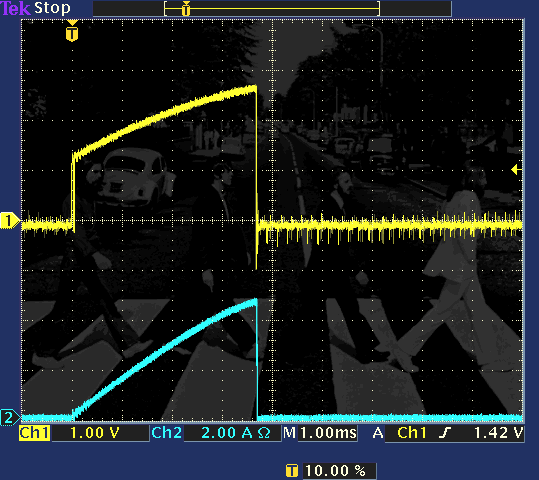
Years ago, I did some measurements on a stock 1.6, looking at the voltage profile of the trigger signal, and it sure as heck appeared as though it was drawing a lot of current into a capacative load.
Now that I do have a DC current probe, I may go and re-test.
But what I'm getting at is that perhaps the MS2 CPU pins simply can't supply enough current to make the stock '90-'93 igniter happy. This would be consistent with our need to run relatively small values of R in the pullups on MS1-style output drivers.
edit: It appears that it was in this very thread:

Yellow is the voltage into the igniter. Blue is coil primary current.
Years ago, I did some measurements on a stock 1.6, looking at the voltage profile of the trigger signal, and it sure as heck appeared as though it was drawing a lot of current into a capacative load.
Now that I do have a DC current probe, I may go and re-test.
But what I'm getting at is that perhaps the MS2 CPU pins simply can't supply enough current to make the stock '90-'93 igniter happy. This would be consistent with our need to run relatively small values of R in the pullups on MS1-style output drivers.
edit: It appears that it was in this very thread:

Yellow is the voltage into the igniter. Blue is coil primary current.
#165
Oh, ok thanks for the clarification! I've got pnp's left over from your mod. My ms2 can run my cops with 100 ohm pullup on your circuit whereas the ms1 couldn't with getting tons of resets. I wanted to try Jasons method and see if I still had resets...
Just curious, isn't Jason's output able to pull more current from 5v on proto then your's and stock setup with vcc?
Or is my elementary understanding of electronics getting in the way again
Just curious, isn't Jason's output able to pull more current from 5v on proto then your's and stock setup with vcc?
Or is my elementary understanding of electronics getting in the way again

If you send me one of your coils with a pigtail, I'll characterize it:
- dwell and drive requirements
- spark output current, voltage, and energy
Last edited by JasonC SBB; 02-27-2012 at 04:20 PM.
#166
Boost Pope


Thread Starter
iTrader: (8)
Join Date: Sep 2005
Location: Chicago. (The less-murder part.)
Posts: 33,026
Total Cats: 6,592
The amount of current which can be supplied to the igniter is only a factor of the value of the pullup resistor which is in series with the feed to the igniter. Additionally, Jason's most recent circuit will deliver less voltage to the igniter, due to the transistor being in series with the supply to the igniter, and thus, decreasing the voltage at the igniter by a value equal to the transistor's collector-emitter forward voltage.
I pointed out earlier in this thread and what you see is not a capacitive charactersitic, but a characteristic of the input of the drive circuitry. The input voltage goes up as current goes up, possibly a side effect of the internal current limiting / protection circuit.
Except that I have determined empirically that the shape of both the igniter voltage curve and the coil primary current curve varies with respect to the value of pullup resistor used in series with the igniter logic drive. Lower values of R produce a sharper rise on the coil primary, and thus, a stronger spark event for all values of dwell which do not exceed the time required to reach full saturation.
#167
I don't really understand how you guys are getting an ignition signal out of D16. I did the mod, and have ignition signal coming out of D14, onto the Stim's LED, but isn't D16 an Accel Enrich light? There isn't any ignition signal coming out of it. So how are yall getting an ignition output out of it?
#168
Boost Czar


iTrader: (62)
Join Date: May 2005
Location: Chantilly, VA
Posts: 79,493
Total Cats: 4,080
I don't really understand how you guys are getting an ignition signal out of D16. I did the mod, and have ignition signal coming out of D14, onto the Stim's LED, but isn't D16 an Accel Enrich light? There isn't any ignition signal coming out of it. So how are yall getting an ignition output out of it?
Unless you've setup your megasquirt to run a single coil...
#170
Boost Pope


Thread Starter
iTrader: (8)
Join Date: Sep 2005
Location: Chicago. (The less-murder part.)
Posts: 33,026
Total Cats: 6,592
Over the years, as the device has grown in capability, many of the original pins / circuits of the MS have been re-purposed to serve different functions. For reasons of laziness / clarity / backwards-compatibility, they have tended to continue to refer to pins by their original names.
This is a matter of software configuration.
#171
Boost Pope


Thread Starter
iTrader: (8)
Join Date: Sep 2005
Location: Chicago. (The less-murder part.)
Posts: 33,026
Total Cats: 6,592

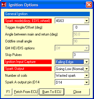
(note that the polarity in this screencap (Going Low) is wrong is you are using my revised spark output mod.)
Specific instructions for NA Miata: http://msextra.com/doc/ms2extra/MS2-Extra_4g63.htm
Specific instructions for NB Miata: http://msextra.com/doc/ms2extra/MS2-Extra_Miata.htm
#175
Boost Pope


Thread Starter
iTrader: (8)
Join Date: Sep 2005
Location: Chicago. (The less-murder part.)
Posts: 33,026
Total Cats: 6,592
The menu structure is different, but all of the basic options are the same between the two pieces of software. TunerStudio is by far the preferred application.
And yes, it is all MSExtra-specific. You cannot run any modern car on a Megasquirt without MSExtra- it is the de-facto firmware run on virtually all MS CPUs. If you purchased your MS2 CPU from a company such as DIYAutotune, it came with MSExtra already installed on it.
#176
Wow alright. This is probably completely wrong but could a different .ini change the menus? Because I've read through three setup threads for TunerStudio on a Miata specifically and none of them mention going a window and changing spark outputs and such. And for the life of me I cannot find the page on TunerStudio. FWIW under "Coil Charging Scheme", TunerStudio is only asking me about EDIS
#178
Ok.. So after reading two threads the conclusion is that this mod helps, but the source of the problem is leaking injectors?
I first got the pop when I installed my SC. Had been running a MS and 550cc injectors for months before. Maybe a bigger chamber (volume) for the air and fuel to mix makes it go pop? vs before it only had the intake manifold ?
This weekend when I turned the key in my car after it had been sitting for 5 days, I did not get a the usual "pop" or "pfff".. I got a god damn cannon shot! KA-BOOOM! Smoke from under the hood etc.. All my neighbours came to their windows to see what the hell was going on...
Nothing broke, no hoses popped of. I still get the same boost levels and the car feels fine.
Yesterday (two days later) I turned the ignition on and I got a very small "pop".
I'll need to fix this.. Can't go around being scared of starting the car. Almost S*** my self the last time


